SlideShare a Scribd company logo
1 of 35
Spanning Tree Protocol Explained and Examples
STP (Spanning Tree Protocol) automatically removes layer 2 switching loops by shutting down the
redundant links. A redundant link is an additional link between two switches. A redundant link is
usually created for backup purposes.
What is the STP ?
STP is a protocol. It actively monitors all links of the network. To finds a redundant link, it uses an
algorithm, known as the STA (spanning-tree algorithm). The STA algorithm first creates a topology
database then it finds and disables the redundant links. Once redundant links are disabled, only the STP-
chosen links remain active. If a new link is added or an existing link is removed, the STP re-runs the STA
algorithm and re-adjusts all links to reflect the change.
Spanning Tree Protocol Explained and Examples
BPDUs
BPDUs (Bridge Protocol Data Unit) are multicast frames which switches use to share information about
themselves and their connections. Besides sharing information, switches also use BPDUs to learn the
network topology, to learn which switch is connected with which switches, and to learn whether any
layer 2 switching loop exists in the learned topology or not.
BPDUS CALCULATION
Before STP decides which path is the best to the Root Bridge, it needs to first decide which switch has to be
elected as the Root Bridge, which is where the Bridge ID comes into play.
Every switch has an identity when they are part of a network. This identity is called the Bridge ID or BID. It is an 8
byte field which is divided into two parts. The first part is a 2-byte Bridge Priority field (which can be configured)
while the second part is the 6-byte MAC address of the switch. While the Bridge Priority is configurable, the MAC
address is unique amongst all switches and the sum of these two ensures a unique Bridge ID.
The above Bridge ID assumes there is one Spanning Tree instance for the entire network. This is also
called Common Spanning-Tree (CST).
As networks begun to grow and become more complex, VLANs were introduced, allowing the creation
of multiple logical and physical networks. It was then necessary to run multiple instances of STP in
order to accommodate each network - VLAN. These multiple instances are called Multiple Spanning
Tree (MST), Per-VLAN Spanning Tree (PVST) and Per-VLAN Spanning Tree Plus (PVST+).
In order to accommodate the additional VLAN information, the Extended System ID field was
introduced, borrowing 12 bits from the original Bridge Priority:
The Bridge Priority value and the Extended System ID
extension together make up a 16 bit (2-byte) value. The
Bridge Priority making up the left most bits, is a value of 0
to 61440. The Extended System ID is a value of 1 to 4095
corresponding to the respective VLAN participating in STP.
The Bridge Priority increments in blocks of 4096 to allow
the System ID Extension to squeeze in between each
increment. This is clearly shown in the analysis:
We should note that the Bridge Priority Field can only be set in increments of 4096. This means that possible values are:
4096, 8192, 12288, 16384, 20480, 24576, 28672, 32768 etc. By default, Cisco’s Per-VLAN Spanning-Tree Plus (PVST+)
adds this System ID Extension (sys-id-ext) to the Bridge Priority.
ROOT BRIDGE ELECTION EXAMPLE
Switch 1 (SW1). Has a priority of 32769 and MAC address of 1111.1111.1111. So its BID becomes
32769.1111.1111.1111. When SW1 creates its own BPDU, it sets both BID and Root BID to 32769.1111.1111.1111.
Switch 2 (SW2). Has a priority of 32769 and MAC address of 2222.2222.2222. So its BID becomes
32769.2222.2222.2222. When SW2 creates its own BPDU, it sets both BID and Root BID to 32769.2222.2222.2222.
Switch 3 (SW3). Has a priority of 32769 and MAC address of 3333.3333.3333. So its BID becomes
32769.3333.3333.3333. When SW3 creates its own BPDU, it sets both BID and Root BID to 32769.3333.3333.3333.
The two values (Bridge Priority + System ID Extension) together make up
the Bridge ID used to elect the Root Bridge
Switch 1 (SW1): It had sent out its own Hello BPDU with both BID and Root BID set to 32769.1111.1111.1111. When it receives the Hello BPDU from SW2, it checks for the Root BID value which is
32769.2222.2222.2222. SW1 discards the BPDU sent by SW2, as it still is the switch with the lowest BID. Same situation happens when it receives the Hello BPDU from SW3. SW1 is still the switch with the
lowest BID. So it discards the Hello BPDU received from SW3 and keeps on advertising itself as the Root Bridge.
Switch 2 (SW2): Just like SW1, SW2 generates and sends its own Hello BPDU with both BID and Root BID set to 32769.2222.2222.2222. When it receives the Hello BPDU from SW1, it checks for the Root
BID value which SW1 has set to 32769.1111.1111.1111. This being lower than SW2's own BID, makes the Hello BPDU received from SW1, a superior BPDU. So in its own BPDU, SW2 changes the value of
the Root BID from 32769.2222.2222.2222, to 32769.1111.1111.1111, and starts advertising this revised Hello BPDU. SW2 now considers SW1 as the Root Bridge. Now, when it receives the Hello BPDU
from SW3, it will obviously discard the BPDU as it is not superior in Root BID value. So for SW2, SW1 remains as Root Bridge, even after receiving the Hello BPDU from SW3.
Switch 3 (SW3): SW3 will send out its own Hello BPDU with both BID and Root BID set to 32769.3333.3333.3333. Depending on which Hello BPDU it receives first i.e. from SW1 or SW2, it will end up
changing the Root BID value in its Hello BPDU because both SW1 & SW2 have lower MAC addresses. So if it received the Hello BPDU from SW2 first, then it will change the Root BID from
32769.3333.3333.3333 to 32769.2222.2222.2222 and consider SW2 as new Root Bridge. Once it receives the Hello BPDU from SW1, this BPDU supersedes the BPDU sent by SW2. So SW3 changes the Root
BID from 32769.2222.2222.2222 to 32769.1111.1111.1111 and now considers SW1 as new Root Bridge.
At this point, all switches have received each other's BPDU and have agreed that SW1 has the lowest BID address and is therefore the rightful Root Bridge of the network. Both SW2, and SW3 now agree that
SW1 is Root Bridge, and start organizing their respective links into Root Ports and Designated Ports.
In most real-life cases, we need to configure the Root Bridge to ensure that no matter the switch that joins the
network, our initial Root Bridge will remain. To achieve this, we simply configure the Bridge Priority so that it is
always smaller than the default value of 32769.
In our example, if we wanted Switch 3 to become the new Root Bridge, we would set its Bridge Priority to 4096
(4096+1 for VLAN 1). By doing so, we change its BID to 4097.3333.3333.3333 making it the lowest amongst our
network switches.
Configuring a new BID in a production network is not recommended unless every caution has been taken to ensure
network downtime is eliminated. When the BID of a switch changes to make it a Root Bridge, the whole network
(switches) will react upon this and begin recomputing the new information. Depending on where the new Root
Bridge is located, switch uplinks and redundant links might be blocked.
WHAT IF WE WANTED SWITCH 3 TO BE THE ROOT BRIDGE?
Spanning Tree Protocol Explained and Examples
Root Bridge
A Root Bridge is the starting point of the STP network topology. To elect a Root Bridge from all switches of the
network, STP uses two parameters; a variable known as bridge priority and the MAC addresses of participating
switches. A switch that has the lowest bridge priority value, is elected as the root bridge. If the bridge priority
value is the same in all switches, the switch which has the lowest MAC address is elected as the Root Bridge.
By default, the bridge priority value is set to 32768 in all Cisco switches. Unless you change this value, a switch
that has the lowest MAC address is elected as the Root Bridge. If you want a specific switch to be elected as the
Root Bridge, you can set the bridge priority value of that switch to less than 32768.
The selection process of the Root Bridge happens each time when a network change occurs like a new switch is
added in the network topology, or an existing switch is removed or the current Root Bridge is failed. If other
switches of the network do not receive BPDUs from the Root Bridge within 20 seconds, they assume that the
Root Bridge has failed. If the current Root Bridge fails, remaining switches automatically start the election
process to choose a new Root Bridge again.
Spanning Tree Protocol Explained and Examples
Non-Root Bridge
Except the Root Bridge, all remaining switches of the network are considered as the Non-Root
Bridges. Non-Root Bridges receive updates from the Root Bridge and update their STP
databases relatively.
Spanning Tree Protocol Explained and Examples
Root cost
Based on the connected media link, STP assigns a value to
each port of the network. This value is known as the port
cost value. STP uses this value to choose the single best path
when multiple links are available between two switches. It
selects the port which has the lowest port cost value.
Spanning Tree Protocol Explained and Examples
Root cost
Bandwidth Old cost value
New Cost Value
10 GB 1
2
1GB 1
4
100 MB 10
19
10 MB 100
100
Some old series switches, like the Catalyst 1900, use the old cost value. Cisco has already discontinued these old
series switches. New series switches, like the 2960, use the new cost value. In the port selection process, the
lower cost value is always preferred over the higher cost value. For example, if two ports; F0 and F1 have cost
value 2 and 4 respectively. The port F0 will be selected.
Spanning Tree Protocol Explained and Examples
Path Cost
Path cost is an accumulated value of the port costs from the Root Bridge to other switches in the network. It is always calculated
from the Root Bridge. Default path cost at the Root Bridge is 0. BPDU contains the path cost information.
When the Root Bridge advertises BPDU out from its interfaces, it sets the path cost to 0. The switch which receives this BPDU
increments the path cost by adding the port cost value of the port on which the BPDU arrived. For example, if the switch
receives the BPDU on the Gigabit interface then the accumulated path cost will be 4.
0 (Value which it received from the Root Bridge) + 4 (Port cost value of the interface on which it received the BPDU) = 4
Now, this switch sets the accumulated path cost (4) in the BPDU and forwards it. The next switch which is connected with this
switch follows the same rule. For example, if the next switch receives this BPDU on the Fast Ethernet port, for that switch, the
accumulated path cost will be 23.
4 (Value which is received) + 19 (Port cost value of the incoming port) = 23.
Spanning Tree Protocol Explained and Examples
Root Port
The Root port is the port that directly connects to the Root Bridge, or has the
shortest path to the Root Bridge. The shortest path is the path that has the
lowest path cost value. Remember that, a switch can go through many other
switches to get the root bridge. So it’s not always the shortest path but it is the
fastest path.
Designated Ports
A designated port is the port that has the lowest port cost value to get on a given
network, compared to other ports on that segment. STP marks the designated
ports as the forwarding ports. Forwarding ports are used to forward the frames.
Spanning Tree Protocol Explained and Examples
A non-designated port is a port that has the higher port cost than the designated port. STP marks
the non-designated port as the blocking port. Blocking ports are used to remove loops.
Non-Designated Ports
All ports on a STP running switch, go through the four different states; blocking, listening,
learning, and forwarding. Through these states, the switch not only understands the network
topology but also calculates the path cost value and based on that value elects the designated and
non-designated ports. After these states, the switch is considered as the STP convergent switch.
Let’s understand each state in detail.
STP port states
Spanning Tree Protocol Explained and Examples
When we power on a switch, the switch puts all of its ports in this state. In this state, the switch only listens and
processes the BPDUs. Except the BPDUs, it drops all other frames. From the incoming BPDUs, it learns the
network topology and determines the ports which will work as the root ports, as the designated ports, and as the
blocked ports.
All ports remain in this state for twenty seconds. After twenty seconds, only the root port and designated ports
move into the next state. Remaining ports stay in this state.
STP Blocking state
Spanning Tree Protocol Explained and Examples
In this state, ports still listen and process only BPDUs. All other frames except BPDUs are dropped. The switch
double checks the layer 2 topology to make sure that no loops occur in the network before processing the
data frames. Ports remain in this state for fifteen seconds.
STP Listening state
In this state, ports still listen and process only BPDUs. All other frames except BPDUs are dropped. The
switch double checks the layer 2 topology to make sure that no loops occur in the network before
processing the data frames. Ports remain in this state for fifteen seconds.
STP Learning state
In this state, the switch listens and processes both BPDUs and user frames. It uses BPDUs to monitor the
network topology. By reading the source address field of users’ frames it also builds and updates CAM table
entries. This state is also referred as the convergence.
STP Forwarding state
Convergence refers to a situation in which all ports of a switch have transitioned to either forwarding or blocking mode. During the STP converging, the switch does not forward
any user frame. Usually, convergence takes place in fifty seconds (20 seconds of the blocking state + 15 seconds of the listing state + 15 seconds of the learning state).
Spanning Tree Protocol Explained and Examples
This state applies to all ports which are either manually shut down or removed from the STP by an
administrator. All unplugged ports also remain in this state. Any port which belongs to this state does not
participate in the STP operation.
STP Blocking state
•All switches of the STP domain, first elect a root bridge. The root bridge acts as a point of
reference for all other switches in the network. All ports of the root bridge remain in the
forwarding mode.
•Once the root bridge is elected, all remaining switches select a single port that has the shortest
path cost to reach the root bridge and marked it as the root port.
•After selecting the root port, switches determine a single designated port for each connection.
•If multiple ports are connected with the same switch or LAN segment, the switch select only one
port that has the lowest path cost and marks it as the designated port.
•Once the root port and designated ports are selected, the switch blocks all remaining ports to
remove any possible or existing loop from the network.
The following image shows how the STP changes a physically looped topology into a virtually
looped free topology.
STP operation in nutshell
Blocking
Listening
Learning
Forwarding
Disabled
Rapid Spanning Tree Protocol
(RSTP)
RSTP Port States
Discarding
Discarding
Learning
Forwarding
STP Port States
Rapid Spanning Tree Protocol
(RSTP)
Alternate and Backup Ports
In RSTP, the election process is the same as STP, except the blocked port is split into two new port
roles: alternate and backup.
Alternate
An alternate port receives BPDUs from another switch but remains in a blocked state. For example, let’s
say a switch has two paths to the root bridge. It will elect one of the two ports as a root port and the other
will become an alternate port. If at any time the root port fails, this redundant path—the alternate port—
will become the new root port.
Backup
A backup port receives BPDUs from its own switch but remains in a blocked state. For example, If a
switch has two ports connecting to different switches, then one port will be elected as a root port and the
other will become the backup port
Rapid Spanning Tree Protocol
(RSTP)
STP Port Priority Overview
When a loop occurs in a network topology, spanning tree can use the port priority value for the ports to
decide which port must be put in forwarding state. The port priority is only used to determine the
topology if the loop in the network cannot be resolved using bridge IDs or path cost.
If a higher priority (lower numerical value) is assigned to a port, STP uses forwarding first. When a lower
priority (higher numerical value) is assigned to a port, STP uses forwarding last. If all ports have the
same priority values, spanning tree puts the lowest numbered interface in forwarding state and blocks all
other interfaces.
Valid interfaces include physical interfaces and port-channel logical interfaces (port-channel port-
channel-number). Acceptable priority values range from 0 to 240, in increments of 16. The default is 128.
Valid priority values are 0, 16, 32, 48, 64, 80, 96, 112, 128, 144, 160, 176, 192, 208, 224, and 240. All
other values are rejected. The lower the number, the higher the priority.
0 16 32 48 64 80 96
11
2
12
8
14
4
16
0
17
6
19
2
20
8
22
4
24
0
Port Priority
STP and RSTP Command list
Purpose
Enabling
STP
switch>enable
switch#configure terminal
switch(config)#spanning-tree vlan vlan-id
switch(config)#end //It is used to exit the configuration mode.
choosing a root
switch
switch>enable
switch#configure
terminal switch(config)#spanning-tree vlan vlan-id root primary
switch(config)#spanning-tree vlan vlan-id root secondary
switch(config)#spanning-tree vlan vlan-id priority priority
switch(config)#end
spanning-tree
mode
switch>enable
switch#configure terminal
switch(config)#spanning-tree mode {pvst | rapid-pvst}
switch(config)#ends
STP and RSTP Command list
Purpose
Shortcut
command
show spanning-tree [summary | root | interface | vlan| brief]
- Show information about a spanning-tree
summary shows summery of port states
root shows status and configuration of root bridge
interface shows spanning-tree interface status and configuration
vlan shows spanning-tree interfaces on specified VLAN
brief shows brief summary of interface information
STP and RSTP Command list
Purpose
Shortcut
command
Switch#show spanning-tree ?
WORD bridge group list, example 1,3-5,7,9
active Report on active interfaces only
backbonefast Show spanning tree backbonefast status
blockedports Show blocked ports
bridge Status and configuration of this bridge
detail Detailed information
inconsistentports Show inconsistent ports
interface Spanning Tree interface status and configuration
mst Multiple spanning trees
pathcost Show Spanning pathcost options
Summary Summary of port states
uplinkfast Show spanning tree uplinkfast status vlan
VLAN Switch Spanning Trees
| Output modifiers
Switch#show spanning-tree
VLAN0001
Spanning tree enabled protocol ieee
Root ID Priority 32769
Address 0012.6620.0800
This bridge is the root
Hello Time 2 sec Max Age 20 sec Forward Delay 15 sec
Bridge ID Priority 32769 (priority 32768 sys-id-ext 1)
Address 0012.6620.0800
Hello Time 2 sec Max Age 20 sec Forward Delay 15 sec
Aging Time 300 sec
Interface Role Sts Cost Prio.Nbr Type
------------------- ---- --- --------- -------- ------------
Gi0/0 Desg FWD 4 128.1 Shr
Gi0/1 Desg FWD 4 128.2 Shr
Gi0/2 Desg FWD 4 128.3 Shr
Gi0/3 Desg FWD 4 128.4 Shr
Shortcut
command
Shortcut
command
Switch#show spanning-tree summary
Switch is in pvst mode
Root bridge for: VLAN0001
Extended system ID is enabled
Portfast Default is disabled
PortFast BPDU Guard Default is disabled
Portfast BPDU Filter Default is disabled
Loopguard Default is disabled
EtherChannel misconfig guard is enabled
Configured Pathcost method used is short
UplinkFast is disabled
BackboneFast is disabled
Name Blocking Listening Learning Forwarding STP Active
---------------------- -------- --------- -------- ---------- ----------
VLAN0001 0 0 0 4 4
---------------------- -------- --------- -------- ---------- ----------
1 vlan 0 0 0 4 4
Shortcut
command
Switch#show spanning-tree root
Root Hello Max Fwd
Vlan Root ID Cost Time Age Dly Root Port
---------------- -------------------- --------- ----- --- --- ---------
---
VLAN0001 32769 0012.6620.0800 0 2 20 15
Switch#
Shortcut
command
Switch#show spanning-tree detail
VLAN0001 is executing the ieee compatible Spanning Tree protocol
Bridge Identifier has priority 32768, sysid 1, address 0012.6620.0800
Configured hello time 2, max age 20, forward delay 15
We are the root of the spanning tree
Topology change flag not set, detected flag not set
Number of topology changes 1 last change occurred 00:25:15 ago
from GigabitEthernet0/0
Times: hold 1, topology change 35, notification 2
hello 2, max age 20, forward delay 15
Timers: hello 1, topology change 0, notification 0, aging 300
Port 1 (GigabitEthernet0/0) of VLAN0001 is designated forwarding
Port path cost 4, Port priority 128, Port Identifier 128.1.
Designated root has priority 32769, address 0012.6620.0800
Designated bridge has priority 32769, address 0012.6620.0800
Designated port id is 128.1, designated path cost 0
Timers: message age 0, forward delay 0, hold 0
Number of transitions to forwarding state: 1
Link type is shared by default
BPDU: sent 773, received 3
Same as all Ethernet port
Shortcut
command
Switch#show spanning-tree interface ?
GigabitEthernet GigabitEthernet IEEE 802.3z
Multilink Multilink-group interface
Port-channel Ethernet Channel of interfaces
Vlan Catalyst Vlans
Switch#show spanning-tree interface gigabitethernet 0/0
Vlan Role Sts Cost Prio.Nbr Type
------------------- ---- --- --------- -------- ------------------------
--------
VLAN0001 Desg FWD 4 128.1 Shr
Switch#show spanning-tree interface gigabitethernet 0/1
Vlan Role Sts Cost Prio.Nbr Type
------------------- ---- --- --------- -------- ------------------------
--------
VLAN0001 Desg FWD 4 128.2 Shr
Switch#
Shortcut
command
Switch#show spanning-tree blockedports
Name Blocked Interfaces List
-------------------- ------------------------------------
Number of blocked ports (segments) in the system : 0
Switch#
Shortcut
command
Switch#show spanning-tree bridge
Hello Max Fwd
Vlan Bridge ID Time Age Dly
Protocol
---------------- --------------------------------- ----- --- --- ----
----
VLAN0001 32769 (32768, 1) 0012.6620.0800 2 20 15 ieee
Switch#
This command show bridge ID information of the switch
Shortcut
command
Switch#show spanning-tree inconsistentports
Name Interface Inconsistency
-------------------- ------------------------ ------------------
Number of inconsistent ports (segments) in the system : 0
Switch#
This command displays ports that are not properly configured in the configuration. E.G if one
port trunk interconnected switches is configured as an Access port, The STP protocol will name
this port consistently.
Switch#show spanning-tree backbonefast
BackboneFast is disabled
STP BackboneFast feature will reduce the delay here from 50 seconds to 30 seconds. By
activating this feature on all Switches in the above image, the max-age timer duration is
skipped. And so, the max-age timer will not be activated and we will save 20 seconds from this
process.
Shortcut
command
Switch#show spanning-tree uplinkfast
UplinkFast is disabled
Switch#
UplinkFast is a Cisco specific feature that improves the convergence
time of the Spanning-Tree Protocol (STP) in the event of the failure of
an uplink. The UplinkFast feature is supported on Cisco Catalyst
4500/4000, 5500/5000, and 6500/6000 series switches running CatOS.
Shortcut
command
Switch#show spanning-tree active
VLAN0001
Spanning tree enabled protocol ieee
Root ID Priority 32769
Address 0012.6620.0800
This bridge is the root
Hello Time 2 sec Max Age 20 sec Forward Delay 15 sec
Bridge ID Priority 32769 (priority 32768 sys-id-ext 1)
Address 0012.6620.0800
Hello Time 2 sec Max Age 20 sec Forward Delay 15 sec
Aging Time 300 sec
Interface Role Sts Cost Prio.Nbr Type
------------------- ---- --- --------- -------- ------------------------
--------
Gi0/0 Desg FWD 4 128.1 Shr
Gi0/1 Desg FWD 4 128.2 Shr
Gi0/2 Desg FWD 4 128.3 Shr
Gi0/3 Desg FWD 4 128.4 Shr
Switch#
Shortcut
command
Switch#show spanning-tree bridge
Hello Max Fwd
Vlan Bridge ID Time Age Dly
Protocol
---------------- --------------------------------- ----- --- --- ----
----
VLAN0001 32769 (32768, 1) 0012.6620.0800 2 20 15 ieee
Switch#
Switch1(config)# interface fastethernet0/1
Switch1(config-if)# spanning-tree portfast
Switch1(config-if)# spanning-tree bpduguard enable
Switch1(config)# spanning-tree portfast bpduguard default
BPDUGUARD
Because PortFast can be enabled on non-trunking ports connecting two switches, spanning-tree loops can occur
because Bridge Protocol Data Units (BPDUs) are still being transmitted and received on those ports.
Layer 2 loops in our network topology can be prevented by enabling another feature called PortFast BPDU
Guard wherein it prevents the loop from happening by moving non-trunking switch ports into
an errdisable state when the Bridge Protocol Data Unit (BPDU) is accepted on that port. Whenever STP BPDU
guard is enabled on the switch, STP shuts down PortFast-configured interfaces on the switch that received
Bridge Protocol Data Unit (BPDU) instead of putting them into STP blocking state.
In a correct configuration, PortFast-configured ports do not receive BPDU. If a PortFast-configured
interface receives a Bridge Protocol Data Unit (BPDU), a misconfiguration exists. BPDU guard provides a
secure response to invalid configurations because the network engineer needs to manually put the interface
in a forwarding state.
Shortcut
command
Switch#show spanning-tree bridge
Hello Max Fwd
Vlan Bridge ID Time Age Dly
Protocol
---------------- --------------------------------- ----- --- --- ----
----
VLAN0001 32769 (32768, 1) 0012.6620.0800 2 20 15 ieee
Switch#
Switch1(config)# interface fastethernet0/1
Switch1(config-if)# spanning-tree portfast
Switch1(config-if)# spanning-tree bpduguard enable
Switch1(config)# spanning-tree portfast bpduguard default
BPDUGUARD
Switch# configure terminal
Enter configuration commands, one per line. End with CNTL/Z.
Switch#(config)# interface fastethernet 3/1
Switch#(config-if)# spanning-tree guard root
Root guards protects the root bridge from being modified without administrator permission by another
switch,
Configuring Root Guard
BPDU Guard, blocks ports assigen to user acces, from being connected to non authorized
switches.
Shortcut
command
Switch#sh spanning-tree vlan 1
VLAN0001
Spanning tree enabled protocol ieee
Root ID Priority 32769
Address 0012.6620.0800
This bridge is the root
Hello Time 2 sec Max Age 20 sec Forward Delay 15 sec
Bridge ID Priority 32769 (priority 32768 sys-id-ext 1)
Address 0012.6620.0800
Hello Time 2 sec Max Age 20 sec Forward Delay 15 sec
Aging Time 300 sec
Interface Role Sts Cost Prio.Nbr Type
------------------- ---- --- --------- -------- ------------------------
--------
Gi0/0 Desg FWD 4 128.1 Shr
Gi0/1 Desg FWD 4 128.2 Shr
Gi0/2 Desg FWD 4 128.3 Shr
Gi0/3 Desg FWD 4 128.4 Shr

More Related Content

Similar to Spanning Tree Protocol and Examples

Spantree
SpantreeSpantree
Spantree
1 2d
 
Spantree
SpantreeSpantree
Spantree
1 2d
 
Ccna 3 chapter 5 v4.0 answers 2011
Ccna 3 chapter 5 v4.0 answers 2011Ccna 3 chapter 5 v4.0 answers 2011
Ccna 3 chapter 5 v4.0 answers 2011
Dân Chơi
 
Switching vla ns_secugenius_harksh_mikemclain_secugenius security solutions
Switching vla ns_secugenius_harksh_mikemclain_secugenius security solutionsSwitching vla ns_secugenius_harksh_mikemclain_secugenius security solutions
Switching vla ns_secugenius_harksh_mikemclain_secugenius security solutions
Mike McLain
 
Configuracion
ConfiguracionConfiguracion
Configuracion
1 2d
 
Configuracion
ConfiguracionConfiguracion
Configuracion
1 2d
 
Spaning Tree Protocol
Spaning Tree ProtocolSpaning Tree Protocol
Spaning Tree Protocol
Atakan ATAK
 
CCNA Advanced Switching
CCNA Advanced SwitchingCCNA Advanced Switching
CCNA Advanced Switching
Dsunte Wilson
 

Similar to Spanning Tree Protocol and Examples (20)

Spantree
SpantreeSpantree
Spantree
 
Spantree
SpantreeSpantree
Spantree
 
Switching
SwitchingSwitching
Switching
 
Ccna 3 chapter 5 v4.0 answers 2011
Ccna 3 chapter 5 v4.0 answers 2011Ccna 3 chapter 5 v4.0 answers 2011
Ccna 3 chapter 5 v4.0 answers 2011
 
Switching vla ns_secugenius_harksh_mikemclain_secugenius security solutions
Switching vla ns_secugenius_harksh_mikemclain_secugenius security solutionsSwitching vla ns_secugenius_harksh_mikemclain_secugenius security solutions
Switching vla ns_secugenius_harksh_mikemclain_secugenius security solutions
 
Ccnp3 lab 3_1_en (hacer)
Ccnp3 lab 3_1_en (hacer)Ccnp3 lab 3_1_en (hacer)
Ccnp3 lab 3_1_en (hacer)
 
Switching
SwitchingSwitching
Switching
 
CCNA PPT
CCNA PPTCCNA PPT
CCNA PPT
 
Ccna day4-140715152437-phpapp01
Ccna day4-140715152437-phpapp01Ccna day4-140715152437-phpapp01
Ccna day4-140715152437-phpapp01
 
Ccna day4
Ccna day4Ccna day4
Ccna day4
 
Ccna day4
Ccna day4Ccna day4
Ccna day4
 
Ccna day4
Ccna day4Ccna day4
Ccna day4
 
02_Layer2_Network_Design.ppt
02_Layer2_Network_Design.ppt02_Layer2_Network_Design.ppt
02_Layer2_Network_Design.ppt
 
Configuracion
ConfiguracionConfiguracion
Configuracion
 
Configuracion
ConfiguracionConfiguracion
Configuracion
 
Spaning Tree Protocol
Spaning Tree ProtocolSpaning Tree Protocol
Spaning Tree Protocol
 
CCNA Advanced Switching
CCNA Advanced SwitchingCCNA Advanced Switching
CCNA Advanced Switching
 
Scaling Networks Lab Manual 1st Edition Cisco Solutions Manual
Scaling Networks Lab Manual 1st Edition Cisco Solutions ManualScaling Networks Lab Manual 1st Edition Cisco Solutions Manual
Scaling Networks Lab Manual 1st Edition Cisco Solutions Manual
 
SRWE_Module_5-STP Concepts.pptx
SRWE_Module_5-STP Concepts.pptxSRWE_Module_5-STP Concepts.pptx
SRWE_Module_5-STP Concepts.pptx
 
Mod10
Mod10Mod10
Mod10
 

More from INFitunes

More from INFitunes (9)

How to Configure Port-Security on Cisco Switch for Enhanced Network Security ...
How to Configure Port-Security on Cisco Switch for Enhanced Network Security ...How to Configure Port-Security on Cisco Switch for Enhanced Network Security ...
How to Configure Port-Security on Cisco Switch for Enhanced Network Security ...
 
ppt cisco exam-001.ppt
ppt cisco exam-001.pptppt cisco exam-001.ppt
ppt cisco exam-001.ppt
 
info grapic template.pptx
info grapic template.pptxinfo grapic template.pptx
info grapic template.pptx
 
IP Subnetting for IPv4.pptx
IP Subnetting for IPv4.pptxIP Subnetting for IPv4.pptx
IP Subnetting for IPv4.pptx
 
Disadvantage Of SSD and limitations
Disadvantage Of SSD and limitations Disadvantage Of SSD and limitations
Disadvantage Of SSD and limitations
 
VLAN, VTP, DTP, Ether channel Cheat Sheet With examples.pptx
VLAN, VTP, DTP, Ether channel  Cheat Sheet With examples.pptxVLAN, VTP, DTP, Ether channel  Cheat Sheet With examples.pptx
VLAN, VTP, DTP, Ether channel Cheat Sheet With examples.pptx
 
Computer mamory units
Computer mamory unitsComputer mamory units
Computer mamory units
 
Basic interview question for Ether Channel.
Basic  interview question for Ether Channel.Basic  interview question for Ether Channel.
Basic interview question for Ether Channel.
 
The osi model layers
The osi model layersThe osi model layers
The osi model layers
 

Recently uploaded

+971581248768>> SAFE AND ORIGINAL ABORTION PILLS FOR SALE IN DUBAI AND ABUDHA...
+971581248768>> SAFE AND ORIGINAL ABORTION PILLS FOR SALE IN DUBAI AND ABUDHA...+971581248768>> SAFE AND ORIGINAL ABORTION PILLS FOR SALE IN DUBAI AND ABUDHA...
+971581248768>> SAFE AND ORIGINAL ABORTION PILLS FOR SALE IN DUBAI AND ABUDHA...
?#DUbAI#??##{{(☎️+971_581248768%)**%*]'#abortion pills for sale in dubai@
 
Modular Monolith - a Practical Alternative to Microservices @ Devoxx UK 2024
Modular Monolith - a Practical Alternative to Microservices @ Devoxx UK 2024Modular Monolith - a Practical Alternative to Microservices @ Devoxx UK 2024
Modular Monolith - a Practical Alternative to Microservices @ Devoxx UK 2024
Victor Rentea
 
Finding Java's Hidden Performance Traps @ DevoxxUK 2024
Finding Java's Hidden Performance Traps @ DevoxxUK 2024Finding Java's Hidden Performance Traps @ DevoxxUK 2024
Finding Java's Hidden Performance Traps @ DevoxxUK 2024
Victor Rentea
 

Recently uploaded (20)

Understanding the FAA Part 107 License ..
Understanding the FAA Part 107 License ..Understanding the FAA Part 107 License ..
Understanding the FAA Part 107 License ..
 
Exploring Multimodal Embeddings with Milvus
Exploring Multimodal Embeddings with MilvusExploring Multimodal Embeddings with Milvus
Exploring Multimodal Embeddings with Milvus
 
presentation ICT roal in 21st century education
presentation ICT roal in 21st century educationpresentation ICT roal in 21st century education
presentation ICT roal in 21st century education
 
+971581248768>> SAFE AND ORIGINAL ABORTION PILLS FOR SALE IN DUBAI AND ABUDHA...
+971581248768>> SAFE AND ORIGINAL ABORTION PILLS FOR SALE IN DUBAI AND ABUDHA...+971581248768>> SAFE AND ORIGINAL ABORTION PILLS FOR SALE IN DUBAI AND ABUDHA...
+971581248768>> SAFE AND ORIGINAL ABORTION PILLS FOR SALE IN DUBAI AND ABUDHA...
 
"I see eyes in my soup": How Delivery Hero implemented the safety system for ...
"I see eyes in my soup": How Delivery Hero implemented the safety system for ..."I see eyes in my soup": How Delivery Hero implemented the safety system for ...
"I see eyes in my soup": How Delivery Hero implemented the safety system for ...
 
Boost Fertility New Invention Ups Success Rates.pdf
Boost Fertility New Invention Ups Success Rates.pdfBoost Fertility New Invention Ups Success Rates.pdf
Boost Fertility New Invention Ups Success Rates.pdf
 
Rising Above_ Dubai Floods and the Fortitude of Dubai International Airport.pdf
Rising Above_ Dubai Floods and the Fortitude of Dubai International Airport.pdfRising Above_ Dubai Floods and the Fortitude of Dubai International Airport.pdf
Rising Above_ Dubai Floods and the Fortitude of Dubai International Airport.pdf
 
Artificial Intelligence Chap.5 : Uncertainty
Artificial Intelligence Chap.5 : UncertaintyArtificial Intelligence Chap.5 : Uncertainty
Artificial Intelligence Chap.5 : Uncertainty
 
CNIC Information System with Pakdata Cf In Pakistan
CNIC Information System with Pakdata Cf In PakistanCNIC Information System with Pakdata Cf In Pakistan
CNIC Information System with Pakdata Cf In Pakistan
 
FWD Group - Insurer Innovation Award 2024
FWD Group - Insurer Innovation Award 2024FWD Group - Insurer Innovation Award 2024
FWD Group - Insurer Innovation Award 2024
 
Apidays New York 2024 - The value of a flexible API Management solution for O...
Apidays New York 2024 - The value of a flexible API Management solution for O...Apidays New York 2024 - The value of a flexible API Management solution for O...
Apidays New York 2024 - The value of a flexible API Management solution for O...
 
Modular Monolith - a Practical Alternative to Microservices @ Devoxx UK 2024
Modular Monolith - a Practical Alternative to Microservices @ Devoxx UK 2024Modular Monolith - a Practical Alternative to Microservices @ Devoxx UK 2024
Modular Monolith - a Practical Alternative to Microservices @ Devoxx UK 2024
 
DEV meet-up UiPath Document Understanding May 7 2024 Amsterdam
DEV meet-up UiPath Document Understanding May 7 2024 AmsterdamDEV meet-up UiPath Document Understanding May 7 2024 Amsterdam
DEV meet-up UiPath Document Understanding May 7 2024 Amsterdam
 
WSO2's API Vision: Unifying Control, Empowering Developers
WSO2's API Vision: Unifying Control, Empowering DevelopersWSO2's API Vision: Unifying Control, Empowering Developers
WSO2's API Vision: Unifying Control, Empowering Developers
 
Apidays New York 2024 - Passkeys: Developing APIs to enable passwordless auth...
Apidays New York 2024 - Passkeys: Developing APIs to enable passwordless auth...Apidays New York 2024 - Passkeys: Developing APIs to enable passwordless auth...
Apidays New York 2024 - Passkeys: Developing APIs to enable passwordless auth...
 
Mcleodganj Call Girls 🥰 8617370543 Service Offer VIP Hot Model
Mcleodganj Call Girls 🥰 8617370543 Service Offer VIP Hot ModelMcleodganj Call Girls 🥰 8617370543 Service Offer VIP Hot Model
Mcleodganj Call Girls 🥰 8617370543 Service Offer VIP Hot Model
 
AWS Community Day CPH - Three problems of Terraform
AWS Community Day CPH - Three problems of TerraformAWS Community Day CPH - Three problems of Terraform
AWS Community Day CPH - Three problems of Terraform
 
Finding Java's Hidden Performance Traps @ DevoxxUK 2024
Finding Java's Hidden Performance Traps @ DevoxxUK 2024Finding Java's Hidden Performance Traps @ DevoxxUK 2024
Finding Java's Hidden Performance Traps @ DevoxxUK 2024
 
DBX First Quarter 2024 Investor Presentation
DBX First Quarter 2024 Investor PresentationDBX First Quarter 2024 Investor Presentation
DBX First Quarter 2024 Investor Presentation
 
TrustArc Webinar - Unlock the Power of AI-Driven Data Discovery
TrustArc Webinar - Unlock the Power of AI-Driven Data DiscoveryTrustArc Webinar - Unlock the Power of AI-Driven Data Discovery
TrustArc Webinar - Unlock the Power of AI-Driven Data Discovery
 

Spanning Tree Protocol and Examples

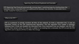
  • 1. Spanning Tree Protocol Explained and Examples STP (Spanning Tree Protocol) automatically removes layer 2 switching loops by shutting down the redundant links. A redundant link is an additional link between two switches. A redundant link is usually created for backup purposes. What is the STP ? STP is a protocol. It actively monitors all links of the network. To finds a redundant link, it uses an algorithm, known as the STA (spanning-tree algorithm). The STA algorithm first creates a topology database then it finds and disables the redundant links. Once redundant links are disabled, only the STP- chosen links remain active. If a new link is added or an existing link is removed, the STP re-runs the STA algorithm and re-adjusts all links to reflect the change.
  • 2. Spanning Tree Protocol Explained and Examples BPDUs BPDUs (Bridge Protocol Data Unit) are multicast frames which switches use to share information about themselves and their connections. Besides sharing information, switches also use BPDUs to learn the network topology, to learn which switch is connected with which switches, and to learn whether any layer 2 switching loop exists in the learned topology or not.
  • 3. BPDUS CALCULATION Before STP decides which path is the best to the Root Bridge, it needs to first decide which switch has to be elected as the Root Bridge, which is where the Bridge ID comes into play. Every switch has an identity when they are part of a network. This identity is called the Bridge ID or BID. It is an 8 byte field which is divided into two parts. The first part is a 2-byte Bridge Priority field (which can be configured) while the second part is the 6-byte MAC address of the switch. While the Bridge Priority is configurable, the MAC address is unique amongst all switches and the sum of these two ensures a unique Bridge ID.
  • 4. The above Bridge ID assumes there is one Spanning Tree instance for the entire network. This is also called Common Spanning-Tree (CST). As networks begun to grow and become more complex, VLANs were introduced, allowing the creation of multiple logical and physical networks. It was then necessary to run multiple instances of STP in order to accommodate each network - VLAN. These multiple instances are called Multiple Spanning Tree (MST), Per-VLAN Spanning Tree (PVST) and Per-VLAN Spanning Tree Plus (PVST+). In order to accommodate the additional VLAN information, the Extended System ID field was introduced, borrowing 12 bits from the original Bridge Priority: The Bridge Priority value and the Extended System ID extension together make up a 16 bit (2-byte) value. The Bridge Priority making up the left most bits, is a value of 0 to 61440. The Extended System ID is a value of 1 to 4095 corresponding to the respective VLAN participating in STP. The Bridge Priority increments in blocks of 4096 to allow the System ID Extension to squeeze in between each increment. This is clearly shown in the analysis: We should note that the Bridge Priority Field can only be set in increments of 4096. This means that possible values are: 4096, 8192, 12288, 16384, 20480, 24576, 28672, 32768 etc. By default, Cisco’s Per-VLAN Spanning-Tree Plus (PVST+) adds this System ID Extension (sys-id-ext) to the Bridge Priority.
  • 5. ROOT BRIDGE ELECTION EXAMPLE Switch 1 (SW1). Has a priority of 32769 and MAC address of 1111.1111.1111. So its BID becomes 32769.1111.1111.1111. When SW1 creates its own BPDU, it sets both BID and Root BID to 32769.1111.1111.1111. Switch 2 (SW2). Has a priority of 32769 and MAC address of 2222.2222.2222. So its BID becomes 32769.2222.2222.2222. When SW2 creates its own BPDU, it sets both BID and Root BID to 32769.2222.2222.2222. Switch 3 (SW3). Has a priority of 32769 and MAC address of 3333.3333.3333. So its BID becomes 32769.3333.3333.3333. When SW3 creates its own BPDU, it sets both BID and Root BID to 32769.3333.3333.3333. The two values (Bridge Priority + System ID Extension) together make up the Bridge ID used to elect the Root Bridge Switch 1 (SW1): It had sent out its own Hello BPDU with both BID and Root BID set to 32769.1111.1111.1111. When it receives the Hello BPDU from SW2, it checks for the Root BID value which is 32769.2222.2222.2222. SW1 discards the BPDU sent by SW2, as it still is the switch with the lowest BID. Same situation happens when it receives the Hello BPDU from SW3. SW1 is still the switch with the lowest BID. So it discards the Hello BPDU received from SW3 and keeps on advertising itself as the Root Bridge. Switch 2 (SW2): Just like SW1, SW2 generates and sends its own Hello BPDU with both BID and Root BID set to 32769.2222.2222.2222. When it receives the Hello BPDU from SW1, it checks for the Root BID value which SW1 has set to 32769.1111.1111.1111. This being lower than SW2's own BID, makes the Hello BPDU received from SW1, a superior BPDU. So in its own BPDU, SW2 changes the value of the Root BID from 32769.2222.2222.2222, to 32769.1111.1111.1111, and starts advertising this revised Hello BPDU. SW2 now considers SW1 as the Root Bridge. Now, when it receives the Hello BPDU from SW3, it will obviously discard the BPDU as it is not superior in Root BID value. So for SW2, SW1 remains as Root Bridge, even after receiving the Hello BPDU from SW3. Switch 3 (SW3): SW3 will send out its own Hello BPDU with both BID and Root BID set to 32769.3333.3333.3333. Depending on which Hello BPDU it receives first i.e. from SW1 or SW2, it will end up changing the Root BID value in its Hello BPDU because both SW1 & SW2 have lower MAC addresses. So if it received the Hello BPDU from SW2 first, then it will change the Root BID from 32769.3333.3333.3333 to 32769.2222.2222.2222 and consider SW2 as new Root Bridge. Once it receives the Hello BPDU from SW1, this BPDU supersedes the BPDU sent by SW2. So SW3 changes the Root BID from 32769.2222.2222.2222 to 32769.1111.1111.1111 and now considers SW1 as new Root Bridge. At this point, all switches have received each other's BPDU and have agreed that SW1 has the lowest BID address and is therefore the rightful Root Bridge of the network. Both SW2, and SW3 now agree that SW1 is Root Bridge, and start organizing their respective links into Root Ports and Designated Ports.
  • 6. In most real-life cases, we need to configure the Root Bridge to ensure that no matter the switch that joins the network, our initial Root Bridge will remain. To achieve this, we simply configure the Bridge Priority so that it is always smaller than the default value of 32769. In our example, if we wanted Switch 3 to become the new Root Bridge, we would set its Bridge Priority to 4096 (4096+1 for VLAN 1). By doing so, we change its BID to 4097.3333.3333.3333 making it the lowest amongst our network switches. Configuring a new BID in a production network is not recommended unless every caution has been taken to ensure network downtime is eliminated. When the BID of a switch changes to make it a Root Bridge, the whole network (switches) will react upon this and begin recomputing the new information. Depending on where the new Root Bridge is located, switch uplinks and redundant links might be blocked. WHAT IF WE WANTED SWITCH 3 TO BE THE ROOT BRIDGE?
  • 7. Spanning Tree Protocol Explained and Examples Root Bridge A Root Bridge is the starting point of the STP network topology. To elect a Root Bridge from all switches of the network, STP uses two parameters; a variable known as bridge priority and the MAC addresses of participating switches. A switch that has the lowest bridge priority value, is elected as the root bridge. If the bridge priority value is the same in all switches, the switch which has the lowest MAC address is elected as the Root Bridge. By default, the bridge priority value is set to 32768 in all Cisco switches. Unless you change this value, a switch that has the lowest MAC address is elected as the Root Bridge. If you want a specific switch to be elected as the Root Bridge, you can set the bridge priority value of that switch to less than 32768. The selection process of the Root Bridge happens each time when a network change occurs like a new switch is added in the network topology, or an existing switch is removed or the current Root Bridge is failed. If other switches of the network do not receive BPDUs from the Root Bridge within 20 seconds, they assume that the Root Bridge has failed. If the current Root Bridge fails, remaining switches automatically start the election process to choose a new Root Bridge again.
  • 8. Spanning Tree Protocol Explained and Examples Non-Root Bridge Except the Root Bridge, all remaining switches of the network are considered as the Non-Root Bridges. Non-Root Bridges receive updates from the Root Bridge and update their STP databases relatively.
  • 9. Spanning Tree Protocol Explained and Examples Root cost Based on the connected media link, STP assigns a value to each port of the network. This value is known as the port cost value. STP uses this value to choose the single best path when multiple links are available between two switches. It selects the port which has the lowest port cost value.
  • 10. Spanning Tree Protocol Explained and Examples Root cost Bandwidth Old cost value New Cost Value 10 GB 1 2 1GB 1 4 100 MB 10 19 10 MB 100 100 Some old series switches, like the Catalyst 1900, use the old cost value. Cisco has already discontinued these old series switches. New series switches, like the 2960, use the new cost value. In the port selection process, the lower cost value is always preferred over the higher cost value. For example, if two ports; F0 and F1 have cost value 2 and 4 respectively. The port F0 will be selected.
  • 11. Spanning Tree Protocol Explained and Examples Path Cost Path cost is an accumulated value of the port costs from the Root Bridge to other switches in the network. It is always calculated from the Root Bridge. Default path cost at the Root Bridge is 0. BPDU contains the path cost information. When the Root Bridge advertises BPDU out from its interfaces, it sets the path cost to 0. The switch which receives this BPDU increments the path cost by adding the port cost value of the port on which the BPDU arrived. For example, if the switch receives the BPDU on the Gigabit interface then the accumulated path cost will be 4. 0 (Value which it received from the Root Bridge) + 4 (Port cost value of the interface on which it received the BPDU) = 4 Now, this switch sets the accumulated path cost (4) in the BPDU and forwards it. The next switch which is connected with this switch follows the same rule. For example, if the next switch receives this BPDU on the Fast Ethernet port, for that switch, the accumulated path cost will be 23. 4 (Value which is received) + 19 (Port cost value of the incoming port) = 23.
  • 12. Spanning Tree Protocol Explained and Examples Root Port The Root port is the port that directly connects to the Root Bridge, or has the shortest path to the Root Bridge. The shortest path is the path that has the lowest path cost value. Remember that, a switch can go through many other switches to get the root bridge. So it’s not always the shortest path but it is the fastest path. Designated Ports A designated port is the port that has the lowest port cost value to get on a given network, compared to other ports on that segment. STP marks the designated ports as the forwarding ports. Forwarding ports are used to forward the frames.
  • 13. Spanning Tree Protocol Explained and Examples A non-designated port is a port that has the higher port cost than the designated port. STP marks the non-designated port as the blocking port. Blocking ports are used to remove loops. Non-Designated Ports All ports on a STP running switch, go through the four different states; blocking, listening, learning, and forwarding. Through these states, the switch not only understands the network topology but also calculates the path cost value and based on that value elects the designated and non-designated ports. After these states, the switch is considered as the STP convergent switch. Let’s understand each state in detail. STP port states
  • 14. Spanning Tree Protocol Explained and Examples When we power on a switch, the switch puts all of its ports in this state. In this state, the switch only listens and processes the BPDUs. Except the BPDUs, it drops all other frames. From the incoming BPDUs, it learns the network topology and determines the ports which will work as the root ports, as the designated ports, and as the blocked ports. All ports remain in this state for twenty seconds. After twenty seconds, only the root port and designated ports move into the next state. Remaining ports stay in this state. STP Blocking state
  • 15. Spanning Tree Protocol Explained and Examples In this state, ports still listen and process only BPDUs. All other frames except BPDUs are dropped. The switch double checks the layer 2 topology to make sure that no loops occur in the network before processing the data frames. Ports remain in this state for fifteen seconds. STP Listening state In this state, ports still listen and process only BPDUs. All other frames except BPDUs are dropped. The switch double checks the layer 2 topology to make sure that no loops occur in the network before processing the data frames. Ports remain in this state for fifteen seconds. STP Learning state In this state, the switch listens and processes both BPDUs and user frames. It uses BPDUs to monitor the network topology. By reading the source address field of users’ frames it also builds and updates CAM table entries. This state is also referred as the convergence. STP Forwarding state Convergence refers to a situation in which all ports of a switch have transitioned to either forwarding or blocking mode. During the STP converging, the switch does not forward any user frame. Usually, convergence takes place in fifty seconds (20 seconds of the blocking state + 15 seconds of the listing state + 15 seconds of the learning state).
  • 16. Spanning Tree Protocol Explained and Examples This state applies to all ports which are either manually shut down or removed from the STP by an administrator. All unplugged ports also remain in this state. Any port which belongs to this state does not participate in the STP operation. STP Blocking state •All switches of the STP domain, first elect a root bridge. The root bridge acts as a point of reference for all other switches in the network. All ports of the root bridge remain in the forwarding mode. •Once the root bridge is elected, all remaining switches select a single port that has the shortest path cost to reach the root bridge and marked it as the root port. •After selecting the root port, switches determine a single designated port for each connection. •If multiple ports are connected with the same switch or LAN segment, the switch select only one port that has the lowest path cost and marks it as the designated port. •Once the root port and designated ports are selected, the switch blocks all remaining ports to remove any possible or existing loop from the network. The following image shows how the STP changes a physically looped topology into a virtually looped free topology. STP operation in nutshell
  • 17. Blocking Listening Learning Forwarding Disabled Rapid Spanning Tree Protocol (RSTP) RSTP Port States Discarding Discarding Learning Forwarding STP Port States
  • 18. Rapid Spanning Tree Protocol (RSTP) Alternate and Backup Ports In RSTP, the election process is the same as STP, except the blocked port is split into two new port roles: alternate and backup. Alternate An alternate port receives BPDUs from another switch but remains in a blocked state. For example, let’s say a switch has two paths to the root bridge. It will elect one of the two ports as a root port and the other will become an alternate port. If at any time the root port fails, this redundant path—the alternate port— will become the new root port. Backup A backup port receives BPDUs from its own switch but remains in a blocked state. For example, If a switch has two ports connecting to different switches, then one port will be elected as a root port and the other will become the backup port
  • 19. Rapid Spanning Tree Protocol (RSTP) STP Port Priority Overview When a loop occurs in a network topology, spanning tree can use the port priority value for the ports to decide which port must be put in forwarding state. The port priority is only used to determine the topology if the loop in the network cannot be resolved using bridge IDs or path cost. If a higher priority (lower numerical value) is assigned to a port, STP uses forwarding first. When a lower priority (higher numerical value) is assigned to a port, STP uses forwarding last. If all ports have the same priority values, spanning tree puts the lowest numbered interface in forwarding state and blocks all other interfaces. Valid interfaces include physical interfaces and port-channel logical interfaces (port-channel port- channel-number). Acceptable priority values range from 0 to 240, in increments of 16. The default is 128. Valid priority values are 0, 16, 32, 48, 64, 80, 96, 112, 128, 144, 160, 176, 192, 208, 224, and 240. All other values are rejected. The lower the number, the higher the priority. 0 16 32 48 64 80 96 11 2 12 8 14 4 16 0 17 6 19 2 20 8 22 4 24 0 Port Priority
  • 20. STP and RSTP Command list Purpose Enabling STP switch>enable switch#configure terminal switch(config)#spanning-tree vlan vlan-id switch(config)#end //It is used to exit the configuration mode. choosing a root switch switch>enable switch#configure terminal switch(config)#spanning-tree vlan vlan-id root primary switch(config)#spanning-tree vlan vlan-id root secondary switch(config)#spanning-tree vlan vlan-id priority priority switch(config)#end spanning-tree mode switch>enable switch#configure terminal switch(config)#spanning-tree mode {pvst | rapid-pvst} switch(config)#ends
  • 21. STP and RSTP Command list Purpose Shortcut command show spanning-tree [summary | root | interface | vlan| brief] - Show information about a spanning-tree summary shows summery of port states root shows status and configuration of root bridge interface shows spanning-tree interface status and configuration vlan shows spanning-tree interfaces on specified VLAN brief shows brief summary of interface information
  • 22. STP and RSTP Command list Purpose Shortcut command Switch#show spanning-tree ? WORD bridge group list, example 1,3-5,7,9 active Report on active interfaces only backbonefast Show spanning tree backbonefast status blockedports Show blocked ports bridge Status and configuration of this bridge detail Detailed information inconsistentports Show inconsistent ports interface Spanning Tree interface status and configuration mst Multiple spanning trees pathcost Show Spanning pathcost options Summary Summary of port states uplinkfast Show spanning tree uplinkfast status vlan VLAN Switch Spanning Trees | Output modifiers Switch#show spanning-tree
  • 23. Switch#show spanning-tree VLAN0001 Spanning tree enabled protocol ieee Root ID Priority 32769 Address 0012.6620.0800 This bridge is the root Hello Time 2 sec Max Age 20 sec Forward Delay 15 sec Bridge ID Priority 32769 (priority 32768 sys-id-ext 1) Address 0012.6620.0800 Hello Time 2 sec Max Age 20 sec Forward Delay 15 sec Aging Time 300 sec Interface Role Sts Cost Prio.Nbr Type ------------------- ---- --- --------- -------- ------------ Gi0/0 Desg FWD 4 128.1 Shr Gi0/1 Desg FWD 4 128.2 Shr Gi0/2 Desg FWD 4 128.3 Shr Gi0/3 Desg FWD 4 128.4 Shr Shortcut command
  • 24. Shortcut command Switch#show spanning-tree summary Switch is in pvst mode Root bridge for: VLAN0001 Extended system ID is enabled Portfast Default is disabled PortFast BPDU Guard Default is disabled Portfast BPDU Filter Default is disabled Loopguard Default is disabled EtherChannel misconfig guard is enabled Configured Pathcost method used is short UplinkFast is disabled BackboneFast is disabled Name Blocking Listening Learning Forwarding STP Active ---------------------- -------- --------- -------- ---------- ---------- VLAN0001 0 0 0 4 4 ---------------------- -------- --------- -------- ---------- ---------- 1 vlan 0 0 0 4 4
  • 25. Shortcut command Switch#show spanning-tree root Root Hello Max Fwd Vlan Root ID Cost Time Age Dly Root Port ---------------- -------------------- --------- ----- --- --- --------- --- VLAN0001 32769 0012.6620.0800 0 2 20 15 Switch#
  • 26. Shortcut command Switch#show spanning-tree detail VLAN0001 is executing the ieee compatible Spanning Tree protocol Bridge Identifier has priority 32768, sysid 1, address 0012.6620.0800 Configured hello time 2, max age 20, forward delay 15 We are the root of the spanning tree Topology change flag not set, detected flag not set Number of topology changes 1 last change occurred 00:25:15 ago from GigabitEthernet0/0 Times: hold 1, topology change 35, notification 2 hello 2, max age 20, forward delay 15 Timers: hello 1, topology change 0, notification 0, aging 300 Port 1 (GigabitEthernet0/0) of VLAN0001 is designated forwarding Port path cost 4, Port priority 128, Port Identifier 128.1. Designated root has priority 32769, address 0012.6620.0800 Designated bridge has priority 32769, address 0012.6620.0800 Designated port id is 128.1, designated path cost 0 Timers: message age 0, forward delay 0, hold 0 Number of transitions to forwarding state: 1 Link type is shared by default BPDU: sent 773, received 3 Same as all Ethernet port
  • 27. Shortcut command Switch#show spanning-tree interface ? GigabitEthernet GigabitEthernet IEEE 802.3z Multilink Multilink-group interface Port-channel Ethernet Channel of interfaces Vlan Catalyst Vlans Switch#show spanning-tree interface gigabitethernet 0/0 Vlan Role Sts Cost Prio.Nbr Type ------------------- ---- --- --------- -------- ------------------------ -------- VLAN0001 Desg FWD 4 128.1 Shr Switch#show spanning-tree interface gigabitethernet 0/1 Vlan Role Sts Cost Prio.Nbr Type ------------------- ---- --- --------- -------- ------------------------ -------- VLAN0001 Desg FWD 4 128.2 Shr Switch#
  • 28. Shortcut command Switch#show spanning-tree blockedports Name Blocked Interfaces List -------------------- ------------------------------------ Number of blocked ports (segments) in the system : 0 Switch#
  • 29. Shortcut command Switch#show spanning-tree bridge Hello Max Fwd Vlan Bridge ID Time Age Dly Protocol ---------------- --------------------------------- ----- --- --- ---- ---- VLAN0001 32769 (32768, 1) 0012.6620.0800 2 20 15 ieee Switch# This command show bridge ID information of the switch
  • 30. Shortcut command Switch#show spanning-tree inconsistentports Name Interface Inconsistency -------------------- ------------------------ ------------------ Number of inconsistent ports (segments) in the system : 0 Switch# This command displays ports that are not properly configured in the configuration. E.G if one port trunk interconnected switches is configured as an Access port, The STP protocol will name this port consistently. Switch#show spanning-tree backbonefast BackboneFast is disabled STP BackboneFast feature will reduce the delay here from 50 seconds to 30 seconds. By activating this feature on all Switches in the above image, the max-age timer duration is skipped. And so, the max-age timer will not be activated and we will save 20 seconds from this process.
  • 31. Shortcut command Switch#show spanning-tree uplinkfast UplinkFast is disabled Switch# UplinkFast is a Cisco specific feature that improves the convergence time of the Spanning-Tree Protocol (STP) in the event of the failure of an uplink. The UplinkFast feature is supported on Cisco Catalyst 4500/4000, 5500/5000, and 6500/6000 series switches running CatOS.
  • 32. Shortcut command Switch#show spanning-tree active VLAN0001 Spanning tree enabled protocol ieee Root ID Priority 32769 Address 0012.6620.0800 This bridge is the root Hello Time 2 sec Max Age 20 sec Forward Delay 15 sec Bridge ID Priority 32769 (priority 32768 sys-id-ext 1) Address 0012.6620.0800 Hello Time 2 sec Max Age 20 sec Forward Delay 15 sec Aging Time 300 sec Interface Role Sts Cost Prio.Nbr Type ------------------- ---- --- --------- -------- ------------------------ -------- Gi0/0 Desg FWD 4 128.1 Shr Gi0/1 Desg FWD 4 128.2 Shr Gi0/2 Desg FWD 4 128.3 Shr Gi0/3 Desg FWD 4 128.4 Shr Switch#
  • 33. Shortcut command Switch#show spanning-tree bridge Hello Max Fwd Vlan Bridge ID Time Age Dly Protocol ---------------- --------------------------------- ----- --- --- ---- ---- VLAN0001 32769 (32768, 1) 0012.6620.0800 2 20 15 ieee Switch# Switch1(config)# interface fastethernet0/1 Switch1(config-if)# spanning-tree portfast Switch1(config-if)# spanning-tree bpduguard enable Switch1(config)# spanning-tree portfast bpduguard default BPDUGUARD Because PortFast can be enabled on non-trunking ports connecting two switches, spanning-tree loops can occur because Bridge Protocol Data Units (BPDUs) are still being transmitted and received on those ports. Layer 2 loops in our network topology can be prevented by enabling another feature called PortFast BPDU Guard wherein it prevents the loop from happening by moving non-trunking switch ports into an errdisable state when the Bridge Protocol Data Unit (BPDU) is accepted on that port. Whenever STP BPDU guard is enabled on the switch, STP shuts down PortFast-configured interfaces on the switch that received Bridge Protocol Data Unit (BPDU) instead of putting them into STP blocking state. In a correct configuration, PortFast-configured ports do not receive BPDU. If a PortFast-configured interface receives a Bridge Protocol Data Unit (BPDU), a misconfiguration exists. BPDU guard provides a secure response to invalid configurations because the network engineer needs to manually put the interface in a forwarding state.
  • 34. Shortcut command Switch#show spanning-tree bridge Hello Max Fwd Vlan Bridge ID Time Age Dly Protocol ---------------- --------------------------------- ----- --- --- ---- ---- VLAN0001 32769 (32768, 1) 0012.6620.0800 2 20 15 ieee Switch# Switch1(config)# interface fastethernet0/1 Switch1(config-if)# spanning-tree portfast Switch1(config-if)# spanning-tree bpduguard enable Switch1(config)# spanning-tree portfast bpduguard default BPDUGUARD Switch# configure terminal Enter configuration commands, one per line. End with CNTL/Z. Switch#(config)# interface fastethernet 3/1 Switch#(config-if)# spanning-tree guard root Root guards protects the root bridge from being modified without administrator permission by another switch, Configuring Root Guard BPDU Guard, blocks ports assigen to user acces, from being connected to non authorized switches.
  • 35. Shortcut command Switch#sh spanning-tree vlan 1 VLAN0001 Spanning tree enabled protocol ieee Root ID Priority 32769 Address 0012.6620.0800 This bridge is the root Hello Time 2 sec Max Age 20 sec Forward Delay 15 sec Bridge ID Priority 32769 (priority 32768 sys-id-ext 1) Address 0012.6620.0800 Hello Time 2 sec Max Age 20 sec Forward Delay 15 sec Aging Time 300 sec Interface Role Sts Cost Prio.Nbr Type ------------------- ---- --- --------- -------- ------------------------ -------- Gi0/0 Desg FWD 4 128.1 Shr Gi0/1 Desg FWD 4 128.2 Shr Gi0/2 Desg FWD 4 128.3 Shr Gi0/3 Desg FWD 4 128.4 Shr