SlideShare a Scribd company logo
1 of 151
EC8252 JANSONS INSTITUTE OF TECHNOLOGY
QUESTION BANK
EC8252 – ELECTRONIC DEVICES
SEMESTER: II Prepared by: Mr.P.GOWTHAM AP/ECE
Mr.KABILESH.S.K AP/ECE
Unit 1
Part A
1. What is meant by diffusion current?
A concentration gradient exists, if the number of either electrons or holes is greater in
one region of a semiconductor as compared to the rest of the region. The holes and electron
tend to move from region of higher concentration to the region of lower concentration. This
process in called diffusion and the current produced due this movement is diffusion current.
2. Define storage time.
The interval time for the stored minority charge to become zero is called storage time.
It is represented as ts.
3. Define drift current.
When an electric field is applied across the semiconductor, the holes move towards
the negative terminal of the battery and electron move towards the positive terminal of the
battery. This drift movement of charge carriers will result in a current termed as drift current.
4. What is meant by doping in semiconductor?
The process of adding impurities to the semiconductor is called doping. The impurity
is called dopant.
5. What is barrier potential?
Because of the oppositely charged ions present on both sides of PN junction an
electric potential is established across the junction even without any external voltage source
which is termed as barrier potential.
JANSONS INSTITUTE OF TECHNOLOGY
DEPARTMENT OF ECE
EC8252 JANSONS INSTITUTE OF TECHNOLOGY
6. Consider si PN junction at T=300K with doping concentrations of Na = 1016
cm-3
and
Nd = 1015
cm-3
. Assume that ni = 1.5×10¹⁰
cm-3
. Calculate width of the space charge
region in a PN junction, when reverse bias voltage VR = 5v is applied.
7. Sketch forward bias characteristics of PN junction diode.
8. Define mass action law.
Under thermal equilibrium the product of free electron concentration (n) and hole
concentration (p) is constant regardless of the individual magnitude n*p = ni
2
.
9. What is meant by peak inverse voltage?
Peak inverse voltage is the maximum reverse voltage that can be applied to the PN
junction without damage to the junction.
EC8252 JANSONS INSTITUTE OF TECHNOLOGY
10. Consider si PN junction at T=300K so that ni = 1.5×10¹⁰
cm-3
the n type doping is
1016
cm-3
and forward bias of 0.60v is applied in the PN junction. Calculate minority
hole concentration at the edge of the space charge region.
11. Find the voltage at which reverse current in a germanium PN junction diode attains
a value of 90% of its saturation value at room temperature.
12. Sketch the energy band diagram of PN junction diode.
EC8252 JANSONS INSTITUTE OF TECHNOLOGY
13. What is the total current at the junction of pn junction diode?
The total in the junction is due to the hole current entering the n material and the
electron current entering the p material. Total current is given by
I = Ipn (0) + Inp (0)
Where,
I – Total current
Ipn (0) - hole current entering the n material
Inp (0) - electron current entering the p material.
14. What is depletion region in PN junction?
The region around the junction from which the mobile charge carriers (electrons and
holes) are depleted is called as depletion region. Since this region has immobile ions, which
are electrically charged, the depletion region is also known as space charge region.
15. What is Reverse saturation current?
The current due to the minority carriers in reverse bias is said to be reverse saturation
current. This current is independent of the value of the reverse bias voltage.
16. What is recovery time? Give its types.
When a diode has its state changed from one type of bias to other a transient
accompanies the diode response, i.e., the diode reaches steady state only after an interval of
time “ tr” called as recovery time. The recovery time can be divided in to two types such as
(i) Forward recovery time
(ii) Reverse recovery time
17. Write the application of pn diode
 can be used as rectifier in DC Power Supplies.
 In Demodulation or Detector Circuits.
 In clamping networks used as DC Restorers
 In clipping circuits used for waveform generation.
 As switches in digital logic circuits.
 In demodulation circuits.
18.Differentiate between drift and diffusion currents.
Drift current
1. It is developed due to potential gradient.
2. This phenomenon is found both in metals and semiconductors
Diffusion current
1. It is developed due to charge concentration gradient.
2. This phenomenon is found only in metals
19. Define transition time.
The time when the diode has normally recovered and the diode reverse current
reaches reverse saturation current Io is called as transition time. It is represented as tt
EC8252 JANSONS INSTITUTE OF TECHNOLOGY
20. What are semiconductors?
The materials whose electrical property lies between those of conductors and
insulators are known as Semiconductors. Ex germanium, silicon.
It has two types.
1. Intrinsic semiconductor 2. Extrinsic semiconductor.
PART B
1. Explain the operation of PN junction under zero voltage applied bias condition and derive
the expression for build in potential barrier. (13)
2. Calculate build in potential barrier in a PN junction. Consider a silicon PN junction at 300k
with doping densities Na= 1 × 10 18
cm-3
and Nd= 1 × 10 15
cm-3
. Assume ni = 1.5 × 10¹⁰
cm-3
.
(4)
3. Explain the basic structure of PN junction (8).
4. Write short notes on diode switching characteristics (8).
5. Describe the action of PN junction diode under forward bias and reverse bias (10).
6. Explain and derive diode current equation (13).
7. Explain how barrier potential developed at PN junction (4).
8. Derive the expression of drift current density (13).
9. Derive the expression of diffusion current density (13).
10. Describe the deviation of VI characteristics of PN junction diode from its ideal (4).
11. Determine ideal reverse saturation current density in a silicon PN junction at T=300k.
Consider the following parameters in silicon PN junction: Na= Nd= 10 16
cm-3
, ni = 1.5 × 10¹⁰
cm-3
, Dn = 25 cm2
/s , Tpo=Tno= 5×10⁻⁷
s , Dp = 10 cm2
/s , £r = 11.7. Comment on the results.
(4).
12. Describe the construction of PN junction diode. Explain the forward and reverse
characteristics of PN junction diode and obtain it VI characteristic curve. (13)
13. Derive the expression of PN junction diode forward and reverse current with suitable
diagrams. (13)
14. Diode current is 0.6 mA when the applied voltage is 400 mV and 20 mA when the
applied voltage is 500 mV. Determine η. Assume KT/q = 25 mV. (13).
15. The reverse saturation of silicon PN junction diode is 10µA. Calculate diode current for
forward bias voltage of 0.6 V at 25º C. (6).
16. Discuss the effect of temperature upon the characteristics on PN junction diode (6).
17. What is transition capacitance and derive the expression of transition capacitance of the
PN junction diode (13).
18. Explain the formation of energy band diagram of PN junction diode with necessary
equation and neat sketch (13).
EC8252 JANSONS INSTITUTE OF TECHNOLOGY
Unit 2
Part A
1. What is meant by base width modulation?
A variation of the base-collector voltage results in a variation of the quasi-neutral
width in the base. The gradient of the minority-carrier density in the base therefore changes,
yielding an increased collector current as the collector-base current is increased. This effect is
referred to as the early effect or base width modulation.
2. A transistor has β = 150, find the collector and base current, if IE = 10mA.
3. What are the major difference between a bipolar and unipolar device.
Unipolar Transistor: They use a single charge carrier i.e. either electrons or holes
for the operation. These do not have any junction as they are made up of either N-Type or P-
type.
Bipolar Transistor: As the name suggests two poles i.e. both the electrons and holes
contribute in the operation. Made up of N-type combined with P-type forming a junction
between these two. Common configuration is N-P-N or P-N-P.
4. Calculate the collector and emitter current levels for a BJT with αdc = 0.99, ICBO =
5µA and IB = 20 µA.
EC8252 JANSONS INSTITUTE OF TECHNOLOGY
5. What is meant by thermal run away?
Thermal runaway. The problem with increasing temperature causing increasing
collector current is that more current increase the power dissipated by the transistor which, in
turn, increases its temperature. This self-reinforcing cycle is known as thermal run away,
which may destroy the transistor.
6. The common base d.c current gain of a transistor is 0.967. If the emitter current is
10mA what is the value of base current.
7. Sketch ebers moll model.
8. Define early effect
A variation of the base-collector voltage results in a variation of the quasi-neutral
width in the base. The gradient of the minority-carrier density in the base therefore changes,
yielding an increased collector current as the collector-base current is increased. This effect is
referred to as the early effect.
EC8252 JANSONS INSTITUTE OF TECHNOLOGY
9. Draw the common base configuration
10. If the transistor has α of 0.97, find the value of β.
11. Give some applications of BJT.
The BJT remains a device that excels in some applications, such as discrete circuit
design, due to the very wide selection of BJT types available, and because of its high Trans
conductance and output resistance compared to MOSFETs.
The BJT is also the choice for demanding analog circuits, especially for very-high-
frequency applications, such as radio-frequency circuits for wireless systems.
Bipolar transistors can be combined with MOSFETs in an integrated circuit by using
a BiCMOS process of wafer fabrication to create circuits that take advantage of the
application strengths of both types of transistor.
12. Why BJT is called current controlled device?
The output voltage, current, or power is controlled by the input current in a transistor.
So it is called the current controlled device.
EC8252 JANSONS INSTITUTE OF TECHNOLOGY
13. Collector region of transistor is larger than emitter. Why?
Collector is made physically larger than emitter and base because collector is to
dissipate much power.
14. Among CE, CB, CC which one is most popular. Why?
CE is most popular among the three because it has high gain compared to base and
collector configuration. It has the gain about to 500 that finds excellent usage in audio
frequency applications.
15. Compare CE, CB, CC.
16. Why h parameter model is important for BJT
It is important because:
1. Its values are used on specification sheets
2. It is one model that may be used to analyze circuit behavior
3. It may be used to form the basis of a more accurate transistor model
17. Define current amplification factor
In a transistor amplifier with a.c. input signal, the ratio of change in output current to
be the change in input current is known as the current amplification factor.
18. What do you meant by multi emitter transistor?
Transistor–transistor logic (TTL) is a class of digital circuits built from bipolar
junction transistors (BJT) and resistors. It is called transistor–transistor logic because both
the logic gating function (e.g., AND) and the amplifying function are performed by
transistors.
TTL is notable for being a widespread integrated circuit (IC) family used in many
applications such as computers, industrial controls, test equipment and instrumentation,
consumer electronics, synthesizers, etc.
EC8252 JANSONS INSTITUTE OF TECHNOLOGY
19. Draw the characteristics of CE configuration.
20. Draw the symbolic representation of the two types of the BJT.
EC8252 JANSONS INSTITUTE OF TECHNOLOGY
PART B
1. Define the hybrid parameters of basic transistor circuit in CE configuration and give its
hybrid model (13).
2. Write short notes on early effect (6).
3. Write short notes on Ebers-Moll mode for BJT. (7)
4. Explain NPN transistor common-emitter configuration and draw circuit for determining its
input and output characteristics (10).
5. Define α, β and λ of a transistor. Show how they are related to each other. (6).
6. Draw the ebers-moll model for NPN transistor and give equation for emitter and collector
current (13).
7. Describe the working of PNP junction (10).
8. Discuss the input and output characteristics of CE configuration (10).
9. With relevant expression, sketch and explain h parameter model (13).
10. Derive the expression of Gummel poon model with a neat circuit diagram (13).
11. What is known as current amplification factor? Derive the relationship between the
amplification factor of CE, CC and CB configuration (7).
12. Justify transistor as an amplifier (6).
13. A transistor with IB = 100µA and IC = 2mA. Find α, β, IE. If IB changes to 0.6 mA find β.
(13).
14. Distinguish between h- parameter model and hybrid π model (7).
15. The reverse leakage current of a transistor when connected in CB configuration is 0.2mA
and it is 18µA when the same transistor is connected in CE configuration. Calculate αdc and
βdc of transistor (assume IB = 30mA). (13)
16. Explain PNP transistor common-base configuration and draw circuit for determining its
input and output characteristics (10).
17. Compare CC, CB, and CE configuration (7)
18. How multi emitter transistor is working? Explain it with neat diagram. (13)
EC8252 JANSONS INSTITUTE OF TECHNOLOGY
Unit 3
Part A
1. Compare MOSFET and JFET.
 In JFET the channel is already present so it is called normally ON device. MOSFET is
a normally OFF device because initially there is no channel, on applying Vgs channel
get enhances.
 JFET is type of junction/ depletion FET. MOSFET is a enhancement type FET but it
can also work in depletion mode.
 MOSFET has higher input impedance as compared to JFET because of SiO2 layer at
the input stage so input current Ig=o but If current is not zero for JFET.
 The propagation delay is less in JFET as compared to MOSFET because MOSFETs
have more capacitive effects.
2. Give some application of JFET.
JFET are used at large scale at amplifier circuits, analog switches, it is also used in
AGC systems, voltage regulators and buffer amplifiers.
3. Define pinch off voltage.
As the Gate voltage ( -VGS ) is made more negative, the width of the channel
decreases until no more current flows between the Drain and the Source and the FET is said
to be “pinched-off” (similar to the cut-off region for a BJT). The voltage at which the channel
closes is called the “pinch-off voltage”, (VP).
4. Compare JFET with BJT.
BJT JFET
Unipolar device (current conduction is
only due to one type of majority carrier
either electron or hole).
Bipolar device (current condition, by both
types of carriers, i.e. majority and
minority-electrons and hole).
The operation depends on the control of a
junction depletion width under reverse
bias.
The operation depends on the injection of
minority carries across a forward biased
.junction.
Voltage driven device. The current
through the two terminals is controlled by
a voltage at the third terminal (gate).
Current driven device. The current
through the two terminals is controlled by
a current at the third terminals (base).
Low noise level. High noise level.
High input impedance (due to reverse
bias).
Low input impedance (due to forward
bias).
Gain is characterized by trans
conductance.
Gain is characterized by voltage gain.
Better thermal stability. Better thermal stability.
EC8252 JANSONS INSTITUTE OF TECHNOLOGY
5. What is channel length modulation?
One of several short-channel effects in MOSFET scaling, channel length
modulation (CLM) is a shortening of the length of the inverted channel region with increase
in drain bias for large drain biases.
As the drain voltage increases, its control over the current extends further toward the
source, so the uninverted region expands toward the source, shortening the length of the
channel region, the effect called channel-length modulation.
6. Assume the the p+n junction of a uniformly doped silicon n channel JFET at T=
300K has doping concentration Na = 1018
cm-3
and Nd = 1016
cm-3
. Assume that the
metallurgical channel thickness a is 0.7 µm. calculate the pinch off voltage.
7. What is JFET give the different modes of operation?
The Junction FET transistor is a type of field effect transistor that can be used as an
electrically controlled switch. The electric energy flows through an active channel between
sources to drain terminals. By applying a reverse bias voltage to gate terminal, the channel is
strained so the electric current is switched off completely.
N- Channel JFET and P-Channel JFET.
8. Give the current voltage relationship of the DMOSFET and EMOSFET.
9. Why it is called field effect transistor?
The drain current ID of the transistor is controlled by the electric field that extends
into the channel due to reverse biased voltage applied to the gate, hence this device has been
given the name Field Effect Transistor.
EC8252 JANSONS INSTITUTE OF TECHNOLOGY
10. Why FET is called voltage controlled device.
FET the value of the current depends upon the value of the voltage applied at the gate
and drain. So it is known as voltage controlled device.
11. Define the term threshold voltage.
The threshold voltage, commonly abbreviated as Vth, of a field-effect transistor
(FET) is the value of the gate–source voltage when the conducting channel just begins to
connect the source and drain contacts of the transistor, allowing significant current.
The threshold voltage of a junction field-effect transistor is often called pinch-off
voltage instead, which is somewhat confusing since "pinch off" for an insulated-gate field-
effect transistor is used to refer to the channel pinching that leads to current saturation
behavior under high source–drain bias, even though the current is never off. The term
"threshold voltage" is unambiguous and refers to the same concept in any field-effect
transistor.
12. Differentiate between N and P channel FETs
 In an N channel JFET the current carriers are electrons, whereas the current carriers
are holes in a P channel JFET.
 Mobility of electrons is large in N channel JFET; Mobility of holes is poor in P
channel JFET.
 The input noise is less in N channel JFET than that of P channel JFET.
 The Trans conductance is larger in N channel JFET than that of P channel JFET.
13. Draw the V-I characteristics curve of MOSFET
14. Compare N channel MOSFET with P channel MOSFET.
N-channel MOSFETs have some inherent performance advantages over p-channel
MOSFET’s. The mobility of electrons, which are carriers in the case of an n-channel device,
is about two times greater than that of holes, which are the carriers in the p-channel device.
Thus an n-channel device is faster than a p-channel device. However, PMOS circuits have
following advantages
 PMOS technology is highly controllable.
 It is a low cost process.
 It has good yield and high noise immunity.
In addition to inherent fast speed properly, NMOS device also have following advantages.
EC8252 JANSONS INSTITUTE OF TECHNOLOGY
 Since electron mobility is twice (say) that of hole mobility, an n-channel device will
have one-half the on-resistance or impedance of an equivalent p-channel device with
the same geometry and under the same operating conditions. Thus n-channel
transistors need only halt the size of p-channel devices to achieve the same
impedance. Therefore, n-channel ICs can be smaller for the same complexity or, even
more important, they can be more complex with no increase in silicon area.
 NMOS circuits offer a speed advantage over PMOS due to smaller junction areas.
Since the operating speed of an MOS IC is largely limited by internal RC time
constants and capacitance of diode is directly proportional to its size, an n-channel
junction can have smaller capacitance. This, in turn, improves its speed.
15. Draw the symbols of N channel MOSFET and P channel MOSFET.
PART-B
1. Draw the circuit diagram for obtaining drain and transfer characteristic of an N- channel
JFET. (13)
2. Draw the circuit diagram of the cross section of an Enhancement MOSFET. And also
discuss the drain and transfer characteristics of EMOSFET. (13)
3. With the help of neat sketch and characteristic curve explain the operation of the junction
FET (7).
4. Define and explain the parameters of Trans conductance, drain resistance and amplification
factor of JFET. Establish relation between them. (7)
5. With the help of suitable diagram explain the working of EMOSFET and DMOSFET. (13)
6. What is channel length modulation in MOSFET (6)?
7. Explain the concept of threshold voltage in MOSFET (6).
8. Discuss the drain and transfer characteristics of JFETs (13).
9. Discuss the characteristics of MOSFET (10).
10. Derive an expression for drain current of FET in pinch off region with necessary diagram
(13).
EC8252 JANSONS INSTITUTE OF TECHNOLOGY
Unit 4
Part A
1. Mention some advantage and disadvantage of tunnel diode.
Advantages
 Low noise
 Ease of operation
 High speed
 Low power
Disadvantages
 Voltage range over which it can be operated is 1 V less.
 Being a two terminal device there is no isolation between the input and output circuit.
2. Draw the energy band diagram of metal semiconductor junction after the contact is
made.
3. What are the difference between tunnel diode and ordinary PN junction diode?
tunnel diode p-n diode
Low noise device Moderate noise device
Preferred semiconductors used are Ge and GaAs
Preferred semiconductors used are Ge and
Si
Tunneling current consists of majority
carriers(i.e. electrons from n-side to p-side)
Current consists of minority carriers (i.e.
holes from p-side to n-side)
Doping levels at p and n sides are very high Doping is normal in both p and n sides
At a small value of reverse voltage a large current
flows due to large overlap between conduction
band and valance band. It is useful as frequency
converter.
Leakage Current is extremely small up to
certain reverse bias voltage. Increases
abruptly to extreme high at breakdown
voltage.
It has negative resistance characteristics. Hence it
is useful for reflection amplifiers and oscillators.
It does not have negative resistance and
hence used as detector and RF mixers.
Majority carrier (current) responds much faster to
voltage changes. This is suitable for microwave
applications.
Majority carrier (current) does not respond
so fast to voltage changes. This is suitable
for low frequency applications only.
EC8252 JANSONS INSTITUTE OF TECHNOLOGY
4. Mention the analog and digital application of LDR.
Analog Applications
 Camera Exposure Control
 Auto Slide Focus - dual cell
 Photocopy Machines - density of toner
 Colorimetric Test Equipment
 Densitometer
 Electronic Scales - dual cell
 Automatic Gain Control – modulated light source
 Automated Rear View Mirror
Digital Applications
 Automatic Headlight Dimmer
 Night Light Control
 Oil Burner Flame Out
 Street Light Control
 Absence / Presence (beam breaker)
 Position Sensor
5. Explain zener breakdown
Zener break down takes place when both sides of the junction are very heavily doped
and consequently the depletion layer is thin and consequently the depletion layer is tin. When
a small value of reverse bias voltage is applied, a very strong electric field is set up across the
thin depletion layer. This electric field is enough to break the covalent bonds. Now extremely
large number of free charge carriers are produced which constitute the zener current. This
process is known as zener break down.
6. What is tunneling?
The phenomenon of penetration of the charge carriers directly though the potential
barrier instead of climbing over it is called as tunneling.
7. What is MESFET?
MESFET stands for metal–semiconductor field-effect transistor. It is quite similar
to a JFET in construction and terminology. The difference is that instead of using a p-n
junction for a gate, a Schottky (metal-semiconductor) junction is used.
8. Expand LASER and LDR.
"Light Amplification by Stimulated Emission of Radiation".
Light Dependent Resistor
EC8252 JANSONS INSTITUTE OF TECHNOLOGY
9. Compare between schottky diode and conventional diode.
PN junction diode Schottky diode
1. Here the contact is established between two
semiconductors
1. Here the contact is established between the
semiconductor and metal
2. current conduction is due to both
majority and minority carriers
2. current conduction is only due to
majority carriers
3. large reverse recovery time 3. Small reverse recovery time
4. barrier potential is high about 0.7 V 4. Barrier potential is low about 0.25 V
5. switching speed is less 5. switching speed is high
6. cannot operate at high frequency 6. can operate at very high frequency (>
300MHz)
10. What is metal semiconductor contact?
A metal semiconductor contact is a contact between a metal and a semiconductor which
according to the doping level and requirement may act as a rectifying diode or just a simple
contact between a semiconductor device and the outside world.
11. Mention few applications of varactor diode.
 It is used in variable resonant tank LC circuit. Here C part is varied using varactor
diode.
 AFC (Automatic Frequency Control) where in varactor diode is used to set LO signal.
 Varactor is used as frequency modulator.
 It is used as frequency multiplier in microwave receiver LO.
 It is used as RF phase shifter.
12. Define contact potential in metal semiconductor contact.
The difference of potential between the work function of metal and the work function
of Semiconductor in a metal semiconductor contact is termed as contact potential.
13. Why zener diode is often preferred than PN diode.
When the reverse voltage reaches breakdown voltage in normal PN junction diode the
current through the junction and the power dissipated at the junction will high. Such an
operation is destructive and the diode gets damaged.
Whereas diode can be designed with adequate power dissipation capabilities to
operate in breakdown region. That diode is known as zener diode. It is heavily doped than
ordinary diode.
14. What is varactor diode?
A varactor diode is best explained as a variable capacitor. Think of the depletion
region as a variable dielectric. The diode is placed in reverse bias. The dielectric is “adjusted”
by reverse bias voltage changes.
• Junction capacitance is present in all reverse biased diodes because of the depletion region.
• Junction capacitance is optimized in a varactor diode and is used for high frequencies and
switching applications.
• Varactor diodes are often used for electronic tuning applications in FM radios and
televisions.
EC8252 JANSONS INSTITUTE OF TECHNOLOGY
15. Symbols of special type semiconductors.
PART-B
1. Write short notes on dual gate MOSFET (7).
2. What is meant by tunneling? Explain the VI characteristics of tunnel diode using energy
band diagram (13).
3. Briefly describe the principle and operation of varactor diode and its applications (13).
4. Briefly describe the principle and operation of laser diode (13).
5. Explain the VI characteristics of zener diode. And distinguish between avalanche and
zener breakdown (13).
6. Draw the structure of metal semiconductor junction and explain energy band structure
before and after contact (13).
7. What is schottky diode? Explain the flow of carriers across its junction during forward and
reverse bias condition with the energy band diagram. (13).
8. Describe the VI characteristics of LDR (7).
9. How zener diode can be used as a regulator (6).
10. Write short notes on PINFET, FINFET and CNTFET (13).
EC8252 JANSONS INSTITUTE OF TECHNOLOGY
Unit 5
Part A
1. Draw the two transistor model of SCR.
2. What is the advantage of TRIAC over SCR.?
A triac may be used in some applications in place of inverse parallel SCRs. They are
typically used in dimmer circuits and for control of small universal motors, e.g. in domestic
appliances. They are simpler to trigger as there is only one gate terminal. They can be used to
provide high speed switching of an AC power load. The main advantage of a so called static
switch over a conventional electromechanical relay, contactor etc. is that contact sticking,
bounce and wear are completely eliminated. Thus they are ideal for applications with a high
switching cycle rate. However, triacs may exhibit commutation problems with an inductive
load, and require a snubber connected across the device. For high power or inductive loads, it
is usually better to employ two SCRs connected as in Figure 1.4(a). In this connection, called
inverse parallel or anti-parallel, each SCR is conducting load current for one half cycle, and
has the other half cycle in which to recover blocking. Thus inverse parallel SCRs are more
rugged, easier to protect with fuses, and give no commutation problems on inductive loads.
Also there are limits in the maximum voltage and current ratings that triacs are available in –
800V at 35A and 1000V at 15A are typical maximum ratings offered. The voltage and
current limits on SCRs are much higher than this.
3. What is the principle of operation of LCD?
The principle behind the LCD’s is that when an electrical current is applied to the
liquid crystal molecule, the molecule tends to untwist. This causes the angle of light which is
passing through the molecule of the polarized glass and also cause a change in the angle of
the top polarizing filter. As a result a little light is allowed to pass the polarized glass through
a particular area of the LCD. Thus that particular area will become dark compared to other.
The LCD works on the principle of blocking light. While constructing the LCD’s, a reflected
mirror is arranged at the back. An electrode plane is made of indium-tin oxide which is kept
on top and a polarized glass with a polarizing film is also added on the bottom of the device.
The complete region of the LCD has to be enclosed by a common electrode and above it
should be the liquid crystal matter. Next comes to the second piece of glass with an electrode
EC8252 JANSONS INSTITUTE OF TECHNOLOGY
in the form of the rectangle on the bottom and, on top, another polarizing film. It must be
considered that both the pieces are kept at right angles. When there is no current, the light
passes through the front of the LCD it will be reflected by the mirror and bounced back. As
the electrode is connected to a battery the current from it will cause the liquid crystals
between the common-plane electrode and the electrode shaped like a rectangle to untwist.
Thus the light is blocked from passing through. That particular rectangular area appears
blank.
4. Sketch VI characteristics of UJT.
5. A solar cell is a pn junction device with no voltage directly applied across the
junction. If it is so, how does a solar cell delivers power to the load.
When the sunlight incident on the glass plate in the solar cell. It reaches the junction.
An incident light photon at the junction may collide with a valence electron and impact
sufficient energy to make a transition to the conduction band. As a result, an electron hole
pair is formed. The newly formed electrons are minority carriers in the p region. They move
freely across the junction similarly, holes formed in the n region cross the junction in the
opposite direction. The flow of these electrons and holes across the junction is in a direction
opposite ton the conventional forward current pn junction. Further, it leads to the
accumulation of majority carriers on both sides of the junction. This gives rise to a
photovoltaic voltage across the junction in the open circuit condition.
6. What is meant by regenerative action of SCR.?
When the anode current suddenly reaches a very high value approaching infinity, the
device suddenly triggers into ON state from the original OFF state. This characteristics of the
device is call regenerative action.
EC8252 JANSONS INSTITUTE OF TECHNOLOGY
7. Mention some advantages and disadvantages of LCD.
Advantages of LCD
 Low power is required
 Good contrast
 Low cost
Disadvantage
 Speed of operation is slow.
 Occupies large area
8. Mention the applications of UJT.
 It is used in timing circuits
 It is used in switching circuits
 It is used in phase control circuits
 It can be used as trigger device for SCR and triac.
 It is used in saw tooth generator.
 It is used for pulse generation
9. What is a TRIAC? Give the symbol and structure of TRIAC.
TRIAC is a three terminal bidirectional semiconductor switching device. It can
conduct in both the directions for any desired period. In operation it is equivalent to two
SCR’s connected in antiparallel.
10. Give the application of TRIAC.
1. Heater control
2. Motor speed control
3. Phase control
4. Static switches
11. Give some applications of DIAC.
1. To trigger TRIAC
2. Motor speed control
3. Heat control
4. Light dimmer circuits
EC8252 JANSONS INSTITUTE OF TECHNOLOGY
12. VI characteristics of TRIAC
13. What is a DIAC? Give the basic construction and symbol of DIAC.
DIAC is a two terminal bidirectional semiconductor switching device. . It can conduct
in either direction depending upon the polarity of the voltage applied across its main
terminals. In operation DIAC is equivalent to two 4 layer diodes connected in antiparallel.
14. Why SCR cannot be used as a bidirectional switch.
SCR can do conduction only when anode is positive with respect to cathode with
proper gate current. Therefore, SCR operates only in one direction and cannot be used as
bidirectional switch.
15. Define holding current in a SCR.
Holding current is defined as the minimum value of anode current to keep the SCR
ON.
EC8252 JANSONS INSTITUTE OF TECHNOLOGY
16. VI of diac.
17. How turning off of SCR is done?
1. By reversing the polarity of anode to cathode voltage.
2. By reducing the current through the SCR below holding current.
3. By interrupting anode current by means of momentarily series or parallel switching
18. List the advantages of SCR.
1. SCR can handle and control large currents.
2. Its switching speed is very high
3. It has no moving parts, therefore it gives noiseless operation.
4. Its operating efficiency is high.
19. List the application of SCR.
1. It can be used as a speed controller in DC and AC motors.
2. It can be used as an inverter.
3. It can be used as a converter
4. It is used in battery chargers.
5. It is used for phase control and heater control.
6. It is used in light dimming control circuits
20. Differentiate BJT and UJT.
UJT (Unijunction Transistor): It is a transistor with only one junction and three
terminals: an emitter (E) and two bases (B1 and B2). BJT (Bipolar Junction Transistor): This
type of transistor consists of two junctions and three terminals, namely Emitter "E", Base "B"
and Collector “C". There are two types of BJT, i) PNP and ii) NPN.
EC8252 JANSONS INSTITUTE OF TECHNOLOGY
BJT is bipolar device and it is a current controlled device UJT is device and voltage
controlled device unipolar .In UJT only majority carriers are responsible for current flowing.
But in BJT both the majority & minority carriers are responsible for current flowing. UJT is
unijunction transistor whereas BJT is bi- junction transistor.
21. State the principle of operation of an LED
When a free electron from the higher energy level gets recombined with the hole, it gives the
light output. Here in case of LEDs, the supply of higher level electrons is provided by the
battery connection.
22. Give applications of LCD
 Used as numerical counters for counting production items.
 Analog quantities can also be displayed as a number on a suitable device. (e.g.)
Digital multimeter.
 Used for solid state video displays.
 Used for image sensing circuits.
 Used for numerical display in pocket calculators.
23. Compare LEDs and LCDs.
24. Give some notes on CCD.
A charge-coupled device (CCD) is a device for the movement of electrical charge,
usually from within the device to an area where the charge can be manipulated, for example
conversion into a digital value. This is achieved by "shifting" the signals between stages
within the device one at a time. CCDs move charge between capacitive bins in the device,
with the shift allowing for the transfer of charge between bins. The CCD is a major piece of
technology in digital imaging. In a CCD image sensor, pixels are represented by p-doped
MOS capacitors.
LED LCD
LEDs Consume more power than LCDs. LCD Consumes very less power.
Due to high power requirement,
LED requires external interface circuits (called as
LED Driver Circuit) when driven from ICs.
LCD can be driven directly from IC chips. Driver
Circuits are not required.
The brightness level is very good for LEDs LCDs have moderate brightness level.
Commercially available LEDs have operating
temperature range of -40 to 85 degree celcius.
Comparatively less temperature limit. The
temperature range is limited to -20 to 60 degree
celcius.
Life time is around 1,00,000 hours Due to chemical degradation the life time is
50,000 hours.
LEDs have wide viewing angle.
The viewing angle is 150 degree
The viewing angle for LCD is 100 degree
Operating voltage range is 1.5V to 5VDC. Operating voltage range is 3 to 20 VDC.
EC8252 JANSONS INSTITUTE OF TECHNOLOGY
PART B
1. Draw the basic structure of UJT and explain the VI characteristics of UJT using equivalent
circuits. (13).
2. Draw the VI characteristics and explain the operation of DIAC (7).
3. Draw the VI characteristics and explain the operation of TRIAC (7).
4. Write short notes on phototransistor with necessary diagram and its applications (6).
5. Write short notes on optocouplers with necessary diagram and its applications (6).
6. Write short notes on CCD with necessary diagram and its applications (6).
7. Draw the two transistor model of SCR and explain its breakdown operation (8).
8. Explain the operation of DMOS and VMOS transistors (13).
9. Write short notes on LED with necessary diagram and its applications (6).
10. Write short notes on power BJT and power MOSFET with necessary diagram and its
applications (13).

More Related Content

Similar to EC8252 NOTES 3rd to 5th unit_compressed.pdf

Quantitative Modeling and Simulation of Single-Electron Transistor
Quantitative Modeling and Simulation of Single-Electron TransistorQuantitative Modeling and Simulation of Single-Electron Transistor
Quantitative Modeling and Simulation of Single-Electron TransistorIRJET Journal
 
EC8252-Electronic Devices Question Bank.pdf
EC8252-Electronic Devices Question Bank.pdfEC8252-Electronic Devices Question Bank.pdf
EC8252-Electronic Devices Question Bank.pdfRajaSekaran923497
 
Diodes and semiconductors - an introduction
Diodes and semiconductors - an introductionDiodes and semiconductors - an introduction
Diodes and semiconductors - an introductionUniversity of Essex
 
Introduction gadgets have gained a lot of attention.pdf
Introduction gadgets have gained a lot of attention.pdfIntroduction gadgets have gained a lot of attention.pdf
Introduction gadgets have gained a lot of attention.pdfbkbk37
 
Electronics lecture 1
Electronics lecture 1Electronics lecture 1
Electronics lecture 1georgesismail
 
basic electronics
 basic   electronics basic   electronics
basic electronicsATTO RATHORE
 
The Performance of an Integrated Transformer in a DC/DC Converter
The Performance of an Integrated Transformer in a DC/DC ConverterThe Performance of an Integrated Transformer in a DC/DC Converter
The Performance of an Integrated Transformer in a DC/DC ConverterTELKOMNIKA JOURNAL
 
Slot A Analytical Questions.pdf
Slot A Analytical Questions.pdfSlot A Analytical Questions.pdf
Slot A Analytical Questions.pdfNagaiKumaresan1
 
ECE 6030 Device Electronics.docx
ECE 6030 Device Electronics.docxECE 6030 Device Electronics.docx
ECE 6030 Device Electronics.docxwrite31
 
Method Of Compensation Instability Of Frequency Modulators In The Absence Of ...
Method Of Compensation Instability Of Frequency Modulators In The Absence Of ...Method Of Compensation Instability Of Frequency Modulators In The Absence Of ...
Method Of Compensation Instability Of Frequency Modulators In The Absence Of ...theijes
 
Mw &dc lab (90) iv i
Mw &dc lab (90) iv iMw &dc lab (90) iv i
Mw &dc lab (90) iv iPrabhu Kiran
 
Resonant Response of RLC Circuits
Resonant Response of RLC Circuits Resonant Response of RLC Circuits
Resonant Response of RLC Circuits Sachin Mehta
 
Physics investigatory projec tdocx
Physics investigatory projec tdocxPhysics investigatory projec tdocx
Physics investigatory projec tdocxHrithiksingla
 

Similar to EC8252 NOTES 3rd to 5th unit_compressed.pdf (20)

Quantitative Modeling and Simulation of Single-Electron Transistor
Quantitative Modeling and Simulation of Single-Electron TransistorQuantitative Modeling and Simulation of Single-Electron Transistor
Quantitative Modeling and Simulation of Single-Electron Transistor
 
EC8252-Electronic Devices Question Bank.pdf
EC8252-Electronic Devices Question Bank.pdfEC8252-Electronic Devices Question Bank.pdf
EC8252-Electronic Devices Question Bank.pdf
 
Diodes and semiconductors - an introduction
Diodes and semiconductors - an introductionDiodes and semiconductors - an introduction
Diodes and semiconductors - an introduction
 
AE UNIT I.ppt
AE UNIT I.pptAE UNIT I.ppt
AE UNIT I.ppt
 
Introduction gadgets have gained a lot of attention.pdf
Introduction gadgets have gained a lot of attention.pdfIntroduction gadgets have gained a lot of attention.pdf
Introduction gadgets have gained a lot of attention.pdf
 
Capacitores
CapacitoresCapacitores
Capacitores
 
Lecture 10.pptx
Lecture 10.pptxLecture 10.pptx
Lecture 10.pptx
 
Electronics lecture 1
Electronics lecture 1Electronics lecture 1
Electronics lecture 1
 
Edc unit 8
Edc unit 8Edc unit 8
Edc unit 8
 
basic electronics
 basic   electronics basic   electronics
basic electronics
 
The Performance of an Integrated Transformer in a DC/DC Converter
The Performance of an Integrated Transformer in a DC/DC ConverterThe Performance of an Integrated Transformer in a DC/DC Converter
The Performance of an Integrated Transformer in a DC/DC Converter
 
Slot A Analytical Questions.pdf
Slot A Analytical Questions.pdfSlot A Analytical Questions.pdf
Slot A Analytical Questions.pdf
 
ECE 6030 Device Electronics.docx
ECE 6030 Device Electronics.docxECE 6030 Device Electronics.docx
ECE 6030 Device Electronics.docx
 
Method Of Compensation Instability Of Frequency Modulators In The Absence Of ...
Method Of Compensation Instability Of Frequency Modulators In The Absence Of ...Method Of Compensation Instability Of Frequency Modulators In The Absence Of ...
Method Of Compensation Instability Of Frequency Modulators In The Absence Of ...
 
9. transistors.rr
9. transistors.rr9. transistors.rr
9. transistors.rr
 
9. transistors.rr
9. transistors.rr9. transistors.rr
9. transistors.rr
 
design of chock coil
 design of chock coil design of chock coil
design of chock coil
 
Mw &dc lab (90) iv i
Mw &dc lab (90) iv iMw &dc lab (90) iv i
Mw &dc lab (90) iv i
 
Resonant Response of RLC Circuits
Resonant Response of RLC Circuits Resonant Response of RLC Circuits
Resonant Response of RLC Circuits
 
Physics investigatory projec tdocx
Physics investigatory projec tdocxPhysics investigatory projec tdocx
Physics investigatory projec tdocx
 

More from kabileshsk2

EMF UNIT 1 & 2 NOTES.pdf
EMF UNIT 1 & 2 NOTES.pdfEMF UNIT 1 & 2 NOTES.pdf
EMF UNIT 1 & 2 NOTES.pdfkabileshsk2
 
EC8252 ED NOTES FOR UNIT 1 & 2.pdf
EC8252 ED NOTES FOR UNIT 1 & 2.pdfEC8252 ED NOTES FOR UNIT 1 & 2.pdf
EC8252 ED NOTES FOR UNIT 1 & 2.pdfkabileshsk2
 
Digital Communication full notes.pdf
Digital Communication full notes.pdfDigital Communication full notes.pdf
Digital Communication full notes.pdfkabileshsk2
 
COMMUNICATION THEORY
COMMUNICATION THEORYCOMMUNICATION THEORY
COMMUNICATION THEORYkabileshsk2
 
COMMUNICATION THEORY
COMMUNICATION THEORYCOMMUNICATION THEORY
COMMUNICATION THEORYkabileshsk2
 
PRINCIPLES OF MANAGEMENT
PRINCIPLES OF MANAGEMENTPRINCIPLES OF MANAGEMENT
PRINCIPLES OF MANAGEMENTkabileshsk2
 

More from kabileshsk2 (6)

EMF UNIT 1 & 2 NOTES.pdf
EMF UNIT 1 & 2 NOTES.pdfEMF UNIT 1 & 2 NOTES.pdf
EMF UNIT 1 & 2 NOTES.pdf
 
EC8252 ED NOTES FOR UNIT 1 & 2.pdf
EC8252 ED NOTES FOR UNIT 1 & 2.pdfEC8252 ED NOTES FOR UNIT 1 & 2.pdf
EC8252 ED NOTES FOR UNIT 1 & 2.pdf
 
Digital Communication full notes.pdf
Digital Communication full notes.pdfDigital Communication full notes.pdf
Digital Communication full notes.pdf
 
COMMUNICATION THEORY
COMMUNICATION THEORYCOMMUNICATION THEORY
COMMUNICATION THEORY
 
COMMUNICATION THEORY
COMMUNICATION THEORYCOMMUNICATION THEORY
COMMUNICATION THEORY
 
PRINCIPLES OF MANAGEMENT
PRINCIPLES OF MANAGEMENTPRINCIPLES OF MANAGEMENT
PRINCIPLES OF MANAGEMENT
 

Recently uploaded

POINT- BIOCHEMISTRY SEM 2 ENZYMES UNIT 5.pptx
POINT- BIOCHEMISTRY SEM 2 ENZYMES UNIT 5.pptxPOINT- BIOCHEMISTRY SEM 2 ENZYMES UNIT 5.pptx
POINT- BIOCHEMISTRY SEM 2 ENZYMES UNIT 5.pptxSayali Powar
 
KSHARA STURA .pptx---KSHARA KARMA THERAPY (CAUSTIC THERAPY)————IMP.OF KSHARA ...
KSHARA STURA .pptx---KSHARA KARMA THERAPY (CAUSTIC THERAPY)————IMP.OF KSHARA ...KSHARA STURA .pptx---KSHARA KARMA THERAPY (CAUSTIC THERAPY)————IMP.OF KSHARA ...
KSHARA STURA .pptx---KSHARA KARMA THERAPY (CAUSTIC THERAPY)————IMP.OF KSHARA ...M56BOOKSTORE PRODUCT/SERVICE
 
Types of Journalistic Writing Grade 8.pptx
Types of Journalistic Writing Grade 8.pptxTypes of Journalistic Writing Grade 8.pptx
Types of Journalistic Writing Grade 8.pptxEyham Joco
 
Employee wellbeing at the workplace.pptx
Employee wellbeing at the workplace.pptxEmployee wellbeing at the workplace.pptx
Employee wellbeing at the workplace.pptxNirmalaLoungPoorunde1
 
Framing an Appropriate Research Question 6b9b26d93da94caf993c038d9efcdedb.pdf
Framing an Appropriate Research Question 6b9b26d93da94caf993c038d9efcdedb.pdfFraming an Appropriate Research Question 6b9b26d93da94caf993c038d9efcdedb.pdf
Framing an Appropriate Research Question 6b9b26d93da94caf993c038d9efcdedb.pdfUjwalaBharambe
 
Full Stack Web Development Course for Beginners
Full Stack Web Development Course  for BeginnersFull Stack Web Development Course  for Beginners
Full Stack Web Development Course for BeginnersSabitha Banu
 
Proudly South Africa powerpoint Thorisha.pptx
Proudly South Africa powerpoint Thorisha.pptxProudly South Africa powerpoint Thorisha.pptx
Proudly South Africa powerpoint Thorisha.pptxthorishapillay1
 
Computed Fields and api Depends in the Odoo 17
Computed Fields and api Depends in the Odoo 17Computed Fields and api Depends in the Odoo 17
Computed Fields and api Depends in the Odoo 17Celine George
 
Solving Puzzles Benefits Everyone (English).pptx
Solving Puzzles Benefits Everyone (English).pptxSolving Puzzles Benefits Everyone (English).pptx
Solving Puzzles Benefits Everyone (English).pptxOH TEIK BIN
 
How to Make a Pirate ship Primary Education.pptx
How to Make a Pirate ship Primary Education.pptxHow to Make a Pirate ship Primary Education.pptx
How to Make a Pirate ship Primary Education.pptxmanuelaromero2013
 
18-04-UA_REPORT_MEDIALITERAСY_INDEX-DM_23-1-final-eng.pdf
18-04-UA_REPORT_MEDIALITERAСY_INDEX-DM_23-1-final-eng.pdf18-04-UA_REPORT_MEDIALITERAСY_INDEX-DM_23-1-final-eng.pdf
18-04-UA_REPORT_MEDIALITERAСY_INDEX-DM_23-1-final-eng.pdfssuser54595a
 
internship ppt on smartinternz platform as salesforce developer
internship ppt on smartinternz platform as salesforce developerinternship ppt on smartinternz platform as salesforce developer
internship ppt on smartinternz platform as salesforce developerunnathinaik
 
MARGINALIZATION (Different learners in Marginalized Group
MARGINALIZATION (Different learners in Marginalized GroupMARGINALIZATION (Different learners in Marginalized Group
MARGINALIZATION (Different learners in Marginalized GroupJonathanParaisoCruz
 
Meghan Sutherland In Media Res Media Component
Meghan Sutherland In Media Res Media ComponentMeghan Sutherland In Media Res Media Component
Meghan Sutherland In Media Res Media ComponentInMediaRes1
 
Enzyme, Pharmaceutical Aids, Miscellaneous Last Part of Chapter no 5th.pdf
Enzyme, Pharmaceutical Aids, Miscellaneous Last Part of Chapter no 5th.pdfEnzyme, Pharmaceutical Aids, Miscellaneous Last Part of Chapter no 5th.pdf
Enzyme, Pharmaceutical Aids, Miscellaneous Last Part of Chapter no 5th.pdfSumit Tiwari
 
Introduction to ArtificiaI Intelligence in Higher Education
Introduction to ArtificiaI Intelligence in Higher EducationIntroduction to ArtificiaI Intelligence in Higher Education
Introduction to ArtificiaI Intelligence in Higher Educationpboyjonauth
 
call girls in Kamla Market (DELHI) 🔝 >༒9953330565🔝 genuine Escort Service 🔝✔️✔️
call girls in Kamla Market (DELHI) 🔝 >༒9953330565🔝 genuine Escort Service 🔝✔️✔️call girls in Kamla Market (DELHI) 🔝 >༒9953330565🔝 genuine Escort Service 🔝✔️✔️
call girls in Kamla Market (DELHI) 🔝 >༒9953330565🔝 genuine Escort Service 🔝✔️✔️9953056974 Low Rate Call Girls In Saket, Delhi NCR
 

Recently uploaded (20)

TataKelola dan KamSiber Kecerdasan Buatan v022.pdf
TataKelola dan KamSiber Kecerdasan Buatan v022.pdfTataKelola dan KamSiber Kecerdasan Buatan v022.pdf
TataKelola dan KamSiber Kecerdasan Buatan v022.pdf
 
POINT- BIOCHEMISTRY SEM 2 ENZYMES UNIT 5.pptx
POINT- BIOCHEMISTRY SEM 2 ENZYMES UNIT 5.pptxPOINT- BIOCHEMISTRY SEM 2 ENZYMES UNIT 5.pptx
POINT- BIOCHEMISTRY SEM 2 ENZYMES UNIT 5.pptx
 
KSHARA STURA .pptx---KSHARA KARMA THERAPY (CAUSTIC THERAPY)————IMP.OF KSHARA ...
KSHARA STURA .pptx---KSHARA KARMA THERAPY (CAUSTIC THERAPY)————IMP.OF KSHARA ...KSHARA STURA .pptx---KSHARA KARMA THERAPY (CAUSTIC THERAPY)————IMP.OF KSHARA ...
KSHARA STURA .pptx---KSHARA KARMA THERAPY (CAUSTIC THERAPY)————IMP.OF KSHARA ...
 
Types of Journalistic Writing Grade 8.pptx
Types of Journalistic Writing Grade 8.pptxTypes of Journalistic Writing Grade 8.pptx
Types of Journalistic Writing Grade 8.pptx
 
ESSENTIAL of (CS/IT/IS) class 06 (database)
ESSENTIAL of (CS/IT/IS) class 06 (database)ESSENTIAL of (CS/IT/IS) class 06 (database)
ESSENTIAL of (CS/IT/IS) class 06 (database)
 
Employee wellbeing at the workplace.pptx
Employee wellbeing at the workplace.pptxEmployee wellbeing at the workplace.pptx
Employee wellbeing at the workplace.pptx
 
Framing an Appropriate Research Question 6b9b26d93da94caf993c038d9efcdedb.pdf
Framing an Appropriate Research Question 6b9b26d93da94caf993c038d9efcdedb.pdfFraming an Appropriate Research Question 6b9b26d93da94caf993c038d9efcdedb.pdf
Framing an Appropriate Research Question 6b9b26d93da94caf993c038d9efcdedb.pdf
 
Full Stack Web Development Course for Beginners
Full Stack Web Development Course  for BeginnersFull Stack Web Development Course  for Beginners
Full Stack Web Development Course for Beginners
 
Proudly South Africa powerpoint Thorisha.pptx
Proudly South Africa powerpoint Thorisha.pptxProudly South Africa powerpoint Thorisha.pptx
Proudly South Africa powerpoint Thorisha.pptx
 
Computed Fields and api Depends in the Odoo 17
Computed Fields and api Depends in the Odoo 17Computed Fields and api Depends in the Odoo 17
Computed Fields and api Depends in the Odoo 17
 
Model Call Girl in Tilak Nagar Delhi reach out to us at 🔝9953056974🔝
Model Call Girl in Tilak Nagar Delhi reach out to us at 🔝9953056974🔝Model Call Girl in Tilak Nagar Delhi reach out to us at 🔝9953056974🔝
Model Call Girl in Tilak Nagar Delhi reach out to us at 🔝9953056974🔝
 
Solving Puzzles Benefits Everyone (English).pptx
Solving Puzzles Benefits Everyone (English).pptxSolving Puzzles Benefits Everyone (English).pptx
Solving Puzzles Benefits Everyone (English).pptx
 
How to Make a Pirate ship Primary Education.pptx
How to Make a Pirate ship Primary Education.pptxHow to Make a Pirate ship Primary Education.pptx
How to Make a Pirate ship Primary Education.pptx
 
18-04-UA_REPORT_MEDIALITERAСY_INDEX-DM_23-1-final-eng.pdf
18-04-UA_REPORT_MEDIALITERAСY_INDEX-DM_23-1-final-eng.pdf18-04-UA_REPORT_MEDIALITERAСY_INDEX-DM_23-1-final-eng.pdf
18-04-UA_REPORT_MEDIALITERAСY_INDEX-DM_23-1-final-eng.pdf
 
internship ppt on smartinternz platform as salesforce developer
internship ppt on smartinternz platform as salesforce developerinternship ppt on smartinternz platform as salesforce developer
internship ppt on smartinternz platform as salesforce developer
 
MARGINALIZATION (Different learners in Marginalized Group
MARGINALIZATION (Different learners in Marginalized GroupMARGINALIZATION (Different learners in Marginalized Group
MARGINALIZATION (Different learners in Marginalized Group
 
Meghan Sutherland In Media Res Media Component
Meghan Sutherland In Media Res Media ComponentMeghan Sutherland In Media Res Media Component
Meghan Sutherland In Media Res Media Component
 
Enzyme, Pharmaceutical Aids, Miscellaneous Last Part of Chapter no 5th.pdf
Enzyme, Pharmaceutical Aids, Miscellaneous Last Part of Chapter no 5th.pdfEnzyme, Pharmaceutical Aids, Miscellaneous Last Part of Chapter no 5th.pdf
Enzyme, Pharmaceutical Aids, Miscellaneous Last Part of Chapter no 5th.pdf
 
Introduction to ArtificiaI Intelligence in Higher Education
Introduction to ArtificiaI Intelligence in Higher EducationIntroduction to ArtificiaI Intelligence in Higher Education
Introduction to ArtificiaI Intelligence in Higher Education
 
call girls in Kamla Market (DELHI) 🔝 >༒9953330565🔝 genuine Escort Service 🔝✔️✔️
call girls in Kamla Market (DELHI) 🔝 >༒9953330565🔝 genuine Escort Service 🔝✔️✔️call girls in Kamla Market (DELHI) 🔝 >༒9953330565🔝 genuine Escort Service 🔝✔️✔️
call girls in Kamla Market (DELHI) 🔝 >༒9953330565🔝 genuine Escort Service 🔝✔️✔️
 

EC8252 NOTES 3rd to 5th unit_compressed.pdf

  • 1.
  • 2.
  • 3.
  • 4.
  • 5.
  • 6.
  • 7.
  • 8.
  • 9.
  • 10.
  • 11.
  • 12.
  • 13.
  • 14.
  • 15.
  • 16.
  • 17.
  • 18.
  • 19.
  • 20.
  • 21.
  • 22.
  • 23.
  • 24.
  • 25.
  • 26.
  • 27.
  • 28.
  • 29.
  • 30.
  • 31.
  • 32.
  • 33.
  • 34.
  • 35.
  • 36.
  • 37.
  • 38.
  • 39.
  • 40.
  • 41.
  • 42.
  • 43.
  • 44.
  • 45.
  • 46.
  • 47.
  • 48.
  • 49.
  • 50.
  • 51.
  • 52.
  • 53.
  • 54.
  • 55.
  • 56.
  • 57.
  • 58.
  • 59.
  • 60.
  • 61.
  • 62.
  • 63.
  • 64.
  • 65.
  • 66.
  • 67.
  • 68.
  • 69.
  • 70.
  • 71.
  • 72.
  • 73.
  • 74.
  • 75.
  • 76.
  • 77.
  • 78.
  • 79.
  • 80.
  • 81.
  • 82.
  • 83.
  • 84.
  • 85.
  • 86.
  • 87.
  • 88.
  • 89.
  • 90.
  • 91.
  • 92.
  • 93.
  • 94.
  • 95.
  • 96.
  • 97.
  • 98.
  • 99.
  • 100.
  • 101.
  • 102.
  • 103.
  • 104.
  • 105.
  • 106.
  • 107.
  • 108.
  • 109.
  • 110.
  • 111.
  • 112.
  • 113.
  • 114.
  • 115.
  • 116.
  • 117.
  • 118.
  • 119.
  • 120.
  • 121.
  • 122.
  • 123.
  • 124.
  • 125.
  • 126. EC8252 JANSONS INSTITUTE OF TECHNOLOGY QUESTION BANK EC8252 – ELECTRONIC DEVICES SEMESTER: II Prepared by: Mr.P.GOWTHAM AP/ECE Mr.KABILESH.S.K AP/ECE Unit 1 Part A 1. What is meant by diffusion current? A concentration gradient exists, if the number of either electrons or holes is greater in one region of a semiconductor as compared to the rest of the region. The holes and electron tend to move from region of higher concentration to the region of lower concentration. This process in called diffusion and the current produced due this movement is diffusion current. 2. Define storage time. The interval time for the stored minority charge to become zero is called storage time. It is represented as ts. 3. Define drift current. When an electric field is applied across the semiconductor, the holes move towards the negative terminal of the battery and electron move towards the positive terminal of the battery. This drift movement of charge carriers will result in a current termed as drift current. 4. What is meant by doping in semiconductor? The process of adding impurities to the semiconductor is called doping. The impurity is called dopant. 5. What is barrier potential? Because of the oppositely charged ions present on both sides of PN junction an electric potential is established across the junction even without any external voltage source which is termed as barrier potential. JANSONS INSTITUTE OF TECHNOLOGY DEPARTMENT OF ECE
  • 127. EC8252 JANSONS INSTITUTE OF TECHNOLOGY 6. Consider si PN junction at T=300K with doping concentrations of Na = 1016 cm-3 and Nd = 1015 cm-3 . Assume that ni = 1.5×1010 cm-3 . Calculate width of the space charge region in a PN junction, when reverse bias voltage VR = 5v is applied. 7. Sketch forward bias characteristics of PN junction diode. 8. Define mass action law. Under thermal equilibrium the product of free electron concentration (n) and hole concentration (p) is constant regardless of the individual magnitude n*p = ni 2 . 9. What is meant by peak inverse voltage? Peak inverse voltage is the maximum reverse voltage that can be applied to the PN junction without damage to the junction.
  • 128. EC8252 JANSONS INSTITUTE OF TECHNOLOGY 10. Consider si PN junction at T=300K so that ni = 1.5×1010 cm-3 the n type doping is 1016 cm-3 and forward bias of 0.60v is applied in the PN junction. Calculate minority hole concentration at the edge of the space charge region. 11. Find the voltage at which reverse current in a germanium PN junction diode attains a value of 90% of its saturation value at room temperature. 12. Sketch the energy band diagram of PN junction diode.
  • 129. EC8252 JANSONS INSTITUTE OF TECHNOLOGY 13. What is the total current at the junction of pn junction diode? The total in the junction is due to the hole current entering the n material and the electron current entering the p material. Total current is given by I = Ipn (0) + Inp (0) Where, I – Total current Ipn (0) - hole current entering the n material Inp (0) - electron current entering the p material. 14. What is depletion region in PN junction? The region around the junction from which the mobile charge carriers (electrons and holes) are depleted is called as depletion region. Since this region has immobile ions, which are electrically charged, the depletion region is also known as space charge region. 15. What is Reverse saturation current? The current due to the minority carriers in reverse bias is said to be reverse saturation current. This current is independent of the value of the reverse bias voltage. 16. What is recovery time? Give its types. When a diode has its state changed from one type of bias to other a transient accompanies the diode response, i.e., the diode reaches steady state only after an interval of time “ tr” called as recovery time. The recovery time can be divided in to two types such as (i) Forward recovery time (ii) Reverse recovery time 17. Write the application of pn diode  can be used as rectifier in DC Power Supplies.  In Demodulation or Detector Circuits.  In clamping networks used as DC Restorers  In clipping circuits used for waveform generation.  As switches in digital logic circuits.  In demodulation circuits. 18.Differentiate between drift and diffusion currents. Drift current 1. It is developed due to potential gradient. 2. This phenomenon is found both in metals and semiconductors Diffusion current 1. It is developed due to charge concentration gradient. 2. This phenomenon is found only in metals 19. Define transition time. The time when the diode has normally recovered and the diode reverse current reaches reverse saturation current Io is called as transition time. It is represented as tt
  • 130. EC8252 JANSONS INSTITUTE OF TECHNOLOGY 20. What are semiconductors? The materials whose electrical property lies between those of conductors and insulators are known as Semiconductors. Ex germanium, silicon. It has two types. 1. Intrinsic semiconductor 2. Extrinsic semiconductor. PART B 1. Explain the operation of PN junction under zero voltage applied bias condition and derive the expression for build in potential barrier. (13) 2. Calculate build in potential barrier in a PN junction. Consider a silicon PN junction at 300k with doping densities Na= 1 × 10 18 cm-3 and Nd= 1 × 10 15 cm-3 . Assume ni = 1.5 × 1010 cm-3 . (4) 3. Explain the basic structure of PN junction (8). 4. Write short notes on diode switching characteristics (8). 5. Describe the action of PN junction diode under forward bias and reverse bias (10). 6. Explain and derive diode current equation (13). 7. Explain how barrier potential developed at PN junction (4). 8. Derive the expression of drift current density (13). 9. Derive the expression of diffusion current density (13). 10. Describe the deviation of VI characteristics of PN junction diode from its ideal (4). 11. Determine ideal reverse saturation current density in a silicon PN junction at T=300k. Consider the following parameters in silicon PN junction: Na= Nd= 10 16 cm-3 , ni = 1.5 × 1010 cm-3 , Dn = 25 cm2 /s , Tpo=Tno= 5×10⁻⁷ s , Dp = 10 cm2 /s , £r = 11.7. Comment on the results. (4). 12. Describe the construction of PN junction diode. Explain the forward and reverse characteristics of PN junction diode and obtain it VI characteristic curve. (13) 13. Derive the expression of PN junction diode forward and reverse current with suitable diagrams. (13) 14. Diode current is 0.6 mA when the applied voltage is 400 mV and 20 mA when the applied voltage is 500 mV. Determine η. Assume KT/q = 25 mV. (13). 15. The reverse saturation of silicon PN junction diode is 10µA. Calculate diode current for forward bias voltage of 0.6 V at 25º C. (6). 16. Discuss the effect of temperature upon the characteristics on PN junction diode (6). 17. What is transition capacitance and derive the expression of transition capacitance of the PN junction diode (13). 18. Explain the formation of energy band diagram of PN junction diode with necessary equation and neat sketch (13).
  • 131. EC8252 JANSONS INSTITUTE OF TECHNOLOGY Unit 2 Part A 1. What is meant by base width modulation? A variation of the base-collector voltage results in a variation of the quasi-neutral width in the base. The gradient of the minority-carrier density in the base therefore changes, yielding an increased collector current as the collector-base current is increased. This effect is referred to as the early effect or base width modulation. 2. A transistor has β = 150, find the collector and base current, if IE = 10mA. 3. What are the major difference between a bipolar and unipolar device. Unipolar Transistor: They use a single charge carrier i.e. either electrons or holes for the operation. These do not have any junction as they are made up of either N-Type or P- type. Bipolar Transistor: As the name suggests two poles i.e. both the electrons and holes contribute in the operation. Made up of N-type combined with P-type forming a junction between these two. Common configuration is N-P-N or P-N-P. 4. Calculate the collector and emitter current levels for a BJT with αdc = 0.99, ICBO = 5µA and IB = 20 µA.
  • 132. EC8252 JANSONS INSTITUTE OF TECHNOLOGY 5. What is meant by thermal run away? Thermal runaway. The problem with increasing temperature causing increasing collector current is that more current increase the power dissipated by the transistor which, in turn, increases its temperature. This self-reinforcing cycle is known as thermal run away, which may destroy the transistor. 6. The common base d.c current gain of a transistor is 0.967. If the emitter current is 10mA what is the value of base current. 7. Sketch ebers moll model. 8. Define early effect A variation of the base-collector voltage results in a variation of the quasi-neutral width in the base. The gradient of the minority-carrier density in the base therefore changes, yielding an increased collector current as the collector-base current is increased. This effect is referred to as the early effect.
  • 133. EC8252 JANSONS INSTITUTE OF TECHNOLOGY 9. Draw the common base configuration 10. If the transistor has α of 0.97, find the value of β. 11. Give some applications of BJT. The BJT remains a device that excels in some applications, such as discrete circuit design, due to the very wide selection of BJT types available, and because of its high Trans conductance and output resistance compared to MOSFETs. The BJT is also the choice for demanding analog circuits, especially for very-high- frequency applications, such as radio-frequency circuits for wireless systems. Bipolar transistors can be combined with MOSFETs in an integrated circuit by using a BiCMOS process of wafer fabrication to create circuits that take advantage of the application strengths of both types of transistor. 12. Why BJT is called current controlled device? The output voltage, current, or power is controlled by the input current in a transistor. So it is called the current controlled device.
  • 134. EC8252 JANSONS INSTITUTE OF TECHNOLOGY 13. Collector region of transistor is larger than emitter. Why? Collector is made physically larger than emitter and base because collector is to dissipate much power. 14. Among CE, CB, CC which one is most popular. Why? CE is most popular among the three because it has high gain compared to base and collector configuration. It has the gain about to 500 that finds excellent usage in audio frequency applications. 15. Compare CE, CB, CC. 16. Why h parameter model is important for BJT It is important because: 1. Its values are used on specification sheets 2. It is one model that may be used to analyze circuit behavior 3. It may be used to form the basis of a more accurate transistor model 17. Define current amplification factor In a transistor amplifier with a.c. input signal, the ratio of change in output current to be the change in input current is known as the current amplification factor. 18. What do you meant by multi emitter transistor? Transistor–transistor logic (TTL) is a class of digital circuits built from bipolar junction transistors (BJT) and resistors. It is called transistor–transistor logic because both the logic gating function (e.g., AND) and the amplifying function are performed by transistors. TTL is notable for being a widespread integrated circuit (IC) family used in many applications such as computers, industrial controls, test equipment and instrumentation, consumer electronics, synthesizers, etc.
  • 135. EC8252 JANSONS INSTITUTE OF TECHNOLOGY 19. Draw the characteristics of CE configuration. 20. Draw the symbolic representation of the two types of the BJT.
  • 136. EC8252 JANSONS INSTITUTE OF TECHNOLOGY PART B 1. Define the hybrid parameters of basic transistor circuit in CE configuration and give its hybrid model (13). 2. Write short notes on early effect (6). 3. Write short notes on Ebers-Moll mode for BJT. (7) 4. Explain NPN transistor common-emitter configuration and draw circuit for determining its input and output characteristics (10). 5. Define α, β and λ of a transistor. Show how they are related to each other. (6). 6. Draw the ebers-moll model for NPN transistor and give equation for emitter and collector current (13). 7. Describe the working of PNP junction (10). 8. Discuss the input and output characteristics of CE configuration (10). 9. With relevant expression, sketch and explain h parameter model (13). 10. Derive the expression of Gummel poon model with a neat circuit diagram (13). 11. What is known as current amplification factor? Derive the relationship between the amplification factor of CE, CC and CB configuration (7). 12. Justify transistor as an amplifier (6). 13. A transistor with IB = 100µA and IC = 2mA. Find α, β, IE. If IB changes to 0.6 mA find β. (13). 14. Distinguish between h- parameter model and hybrid π model (7). 15. The reverse leakage current of a transistor when connected in CB configuration is 0.2mA and it is 18µA when the same transistor is connected in CE configuration. Calculate αdc and βdc of transistor (assume IB = 30mA). (13) 16. Explain PNP transistor common-base configuration and draw circuit for determining its input and output characteristics (10). 17. Compare CC, CB, and CE configuration (7) 18. How multi emitter transistor is working? Explain it with neat diagram. (13)
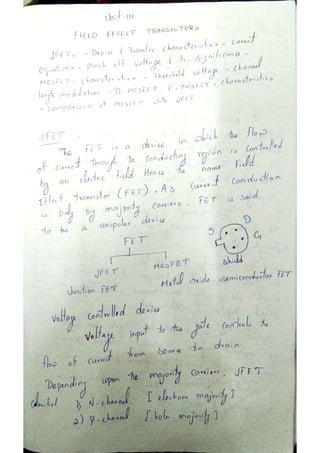
  • 137. EC8252 JANSONS INSTITUTE OF TECHNOLOGY Unit 3 Part A 1. Compare MOSFET and JFET.  In JFET the channel is already present so it is called normally ON device. MOSFET is a normally OFF device because initially there is no channel, on applying Vgs channel get enhances.  JFET is type of junction/ depletion FET. MOSFET is a enhancement type FET but it can also work in depletion mode.  MOSFET has higher input impedance as compared to JFET because of SiO2 layer at the input stage so input current Ig=o but If current is not zero for JFET.  The propagation delay is less in JFET as compared to MOSFET because MOSFETs have more capacitive effects. 2. Give some application of JFET. JFET are used at large scale at amplifier circuits, analog switches, it is also used in AGC systems, voltage regulators and buffer amplifiers. 3. Define pinch off voltage. As the Gate voltage ( -VGS ) is made more negative, the width of the channel decreases until no more current flows between the Drain and the Source and the FET is said to be “pinched-off” (similar to the cut-off region for a BJT). The voltage at which the channel closes is called the “pinch-off voltage”, (VP). 4. Compare JFET with BJT. BJT JFET Unipolar device (current conduction is only due to one type of majority carrier either electron or hole). Bipolar device (current condition, by both types of carriers, i.e. majority and minority-electrons and hole). The operation depends on the control of a junction depletion width under reverse bias. The operation depends on the injection of minority carries across a forward biased .junction. Voltage driven device. The current through the two terminals is controlled by a voltage at the third terminal (gate). Current driven device. The current through the two terminals is controlled by a current at the third terminals (base). Low noise level. High noise level. High input impedance (due to reverse bias). Low input impedance (due to forward bias). Gain is characterized by trans conductance. Gain is characterized by voltage gain. Better thermal stability. Better thermal stability.
  • 138. EC8252 JANSONS INSTITUTE OF TECHNOLOGY 5. What is channel length modulation? One of several short-channel effects in MOSFET scaling, channel length modulation (CLM) is a shortening of the length of the inverted channel region with increase in drain bias for large drain biases. As the drain voltage increases, its control over the current extends further toward the source, so the uninverted region expands toward the source, shortening the length of the channel region, the effect called channel-length modulation. 6. Assume the the p+n junction of a uniformly doped silicon n channel JFET at T= 300K has doping concentration Na = 1018 cm-3 and Nd = 1016 cm-3 . Assume that the metallurgical channel thickness a is 0.7 µm. calculate the pinch off voltage. 7. What is JFET give the different modes of operation? The Junction FET transistor is a type of field effect transistor that can be used as an electrically controlled switch. The electric energy flows through an active channel between sources to drain terminals. By applying a reverse bias voltage to gate terminal, the channel is strained so the electric current is switched off completely. N- Channel JFET and P-Channel JFET. 8. Give the current voltage relationship of the DMOSFET and EMOSFET. 9. Why it is called field effect transistor? The drain current ID of the transistor is controlled by the electric field that extends into the channel due to reverse biased voltage applied to the gate, hence this device has been given the name Field Effect Transistor.
  • 139. EC8252 JANSONS INSTITUTE OF TECHNOLOGY 10. Why FET is called voltage controlled device. FET the value of the current depends upon the value of the voltage applied at the gate and drain. So it is known as voltage controlled device. 11. Define the term threshold voltage. The threshold voltage, commonly abbreviated as Vth, of a field-effect transistor (FET) is the value of the gate–source voltage when the conducting channel just begins to connect the source and drain contacts of the transistor, allowing significant current. The threshold voltage of a junction field-effect transistor is often called pinch-off voltage instead, which is somewhat confusing since "pinch off" for an insulated-gate field- effect transistor is used to refer to the channel pinching that leads to current saturation behavior under high source–drain bias, even though the current is never off. The term "threshold voltage" is unambiguous and refers to the same concept in any field-effect transistor. 12. Differentiate between N and P channel FETs  In an N channel JFET the current carriers are electrons, whereas the current carriers are holes in a P channel JFET.  Mobility of electrons is large in N channel JFET; Mobility of holes is poor in P channel JFET.  The input noise is less in N channel JFET than that of P channel JFET.  The Trans conductance is larger in N channel JFET than that of P channel JFET. 13. Draw the V-I characteristics curve of MOSFET 14. Compare N channel MOSFET with P channel MOSFET. N-channel MOSFETs have some inherent performance advantages over p-channel MOSFET’s. The mobility of electrons, which are carriers in the case of an n-channel device, is about two times greater than that of holes, which are the carriers in the p-channel device. Thus an n-channel device is faster than a p-channel device. However, PMOS circuits have following advantages  PMOS technology is highly controllable.  It is a low cost process.  It has good yield and high noise immunity. In addition to inherent fast speed properly, NMOS device also have following advantages.
  • 140. EC8252 JANSONS INSTITUTE OF TECHNOLOGY  Since electron mobility is twice (say) that of hole mobility, an n-channel device will have one-half the on-resistance or impedance of an equivalent p-channel device with the same geometry and under the same operating conditions. Thus n-channel transistors need only halt the size of p-channel devices to achieve the same impedance. Therefore, n-channel ICs can be smaller for the same complexity or, even more important, they can be more complex with no increase in silicon area.  NMOS circuits offer a speed advantage over PMOS due to smaller junction areas. Since the operating speed of an MOS IC is largely limited by internal RC time constants and capacitance of diode is directly proportional to its size, an n-channel junction can have smaller capacitance. This, in turn, improves its speed. 15. Draw the symbols of N channel MOSFET and P channel MOSFET. PART-B 1. Draw the circuit diagram for obtaining drain and transfer characteristic of an N- channel JFET. (13) 2. Draw the circuit diagram of the cross section of an Enhancement MOSFET. And also discuss the drain and transfer characteristics of EMOSFET. (13) 3. With the help of neat sketch and characteristic curve explain the operation of the junction FET (7). 4. Define and explain the parameters of Trans conductance, drain resistance and amplification factor of JFET. Establish relation between them. (7) 5. With the help of suitable diagram explain the working of EMOSFET and DMOSFET. (13) 6. What is channel length modulation in MOSFET (6)? 7. Explain the concept of threshold voltage in MOSFET (6). 8. Discuss the drain and transfer characteristics of JFETs (13). 9. Discuss the characteristics of MOSFET (10). 10. Derive an expression for drain current of FET in pinch off region with necessary diagram (13).
  • 141. EC8252 JANSONS INSTITUTE OF TECHNOLOGY Unit 4 Part A 1. Mention some advantage and disadvantage of tunnel diode. Advantages  Low noise  Ease of operation  High speed  Low power Disadvantages  Voltage range over which it can be operated is 1 V less.  Being a two terminal device there is no isolation between the input and output circuit. 2. Draw the energy band diagram of metal semiconductor junction after the contact is made. 3. What are the difference between tunnel diode and ordinary PN junction diode? tunnel diode p-n diode Low noise device Moderate noise device Preferred semiconductors used are Ge and GaAs Preferred semiconductors used are Ge and Si Tunneling current consists of majority carriers(i.e. electrons from n-side to p-side) Current consists of minority carriers (i.e. holes from p-side to n-side) Doping levels at p and n sides are very high Doping is normal in both p and n sides At a small value of reverse voltage a large current flows due to large overlap between conduction band and valance band. It is useful as frequency converter. Leakage Current is extremely small up to certain reverse bias voltage. Increases abruptly to extreme high at breakdown voltage. It has negative resistance characteristics. Hence it is useful for reflection amplifiers and oscillators. It does not have negative resistance and hence used as detector and RF mixers. Majority carrier (current) responds much faster to voltage changes. This is suitable for microwave applications. Majority carrier (current) does not respond so fast to voltage changes. This is suitable for low frequency applications only.
  • 142. EC8252 JANSONS INSTITUTE OF TECHNOLOGY 4. Mention the analog and digital application of LDR. Analog Applications  Camera Exposure Control  Auto Slide Focus - dual cell  Photocopy Machines - density of toner  Colorimetric Test Equipment  Densitometer  Electronic Scales - dual cell  Automatic Gain Control – modulated light source  Automated Rear View Mirror Digital Applications  Automatic Headlight Dimmer  Night Light Control  Oil Burner Flame Out  Street Light Control  Absence / Presence (beam breaker)  Position Sensor 5. Explain zener breakdown Zener break down takes place when both sides of the junction are very heavily doped and consequently the depletion layer is thin and consequently the depletion layer is tin. When a small value of reverse bias voltage is applied, a very strong electric field is set up across the thin depletion layer. This electric field is enough to break the covalent bonds. Now extremely large number of free charge carriers are produced which constitute the zener current. This process is known as zener break down. 6. What is tunneling? The phenomenon of penetration of the charge carriers directly though the potential barrier instead of climbing over it is called as tunneling. 7. What is MESFET? MESFET stands for metal–semiconductor field-effect transistor. It is quite similar to a JFET in construction and terminology. The difference is that instead of using a p-n junction for a gate, a Schottky (metal-semiconductor) junction is used. 8. Expand LASER and LDR. "Light Amplification by Stimulated Emission of Radiation". Light Dependent Resistor
  • 143. EC8252 JANSONS INSTITUTE OF TECHNOLOGY 9. Compare between schottky diode and conventional diode. PN junction diode Schottky diode 1. Here the contact is established between two semiconductors 1. Here the contact is established between the semiconductor and metal 2. current conduction is due to both majority and minority carriers 2. current conduction is only due to majority carriers 3. large reverse recovery time 3. Small reverse recovery time 4. barrier potential is high about 0.7 V 4. Barrier potential is low about 0.25 V 5. switching speed is less 5. switching speed is high 6. cannot operate at high frequency 6. can operate at very high frequency (> 300MHz) 10. What is metal semiconductor contact? A metal semiconductor contact is a contact between a metal and a semiconductor which according to the doping level and requirement may act as a rectifying diode or just a simple contact between a semiconductor device and the outside world. 11. Mention few applications of varactor diode.  It is used in variable resonant tank LC circuit. Here C part is varied using varactor diode.  AFC (Automatic Frequency Control) where in varactor diode is used to set LO signal.  Varactor is used as frequency modulator.  It is used as frequency multiplier in microwave receiver LO.  It is used as RF phase shifter. 12. Define contact potential in metal semiconductor contact. The difference of potential between the work function of metal and the work function of Semiconductor in a metal semiconductor contact is termed as contact potential. 13. Why zener diode is often preferred than PN diode. When the reverse voltage reaches breakdown voltage in normal PN junction diode the current through the junction and the power dissipated at the junction will high. Such an operation is destructive and the diode gets damaged. Whereas diode can be designed with adequate power dissipation capabilities to operate in breakdown region. That diode is known as zener diode. It is heavily doped than ordinary diode. 14. What is varactor diode? A varactor diode is best explained as a variable capacitor. Think of the depletion region as a variable dielectric. The diode is placed in reverse bias. The dielectric is “adjusted” by reverse bias voltage changes. • Junction capacitance is present in all reverse biased diodes because of the depletion region. • Junction capacitance is optimized in a varactor diode and is used for high frequencies and switching applications. • Varactor diodes are often used for electronic tuning applications in FM radios and televisions.
  • 144. EC8252 JANSONS INSTITUTE OF TECHNOLOGY 15. Symbols of special type semiconductors. PART-B 1. Write short notes on dual gate MOSFET (7). 2. What is meant by tunneling? Explain the VI characteristics of tunnel diode using energy band diagram (13). 3. Briefly describe the principle and operation of varactor diode and its applications (13). 4. Briefly describe the principle and operation of laser diode (13). 5. Explain the VI characteristics of zener diode. And distinguish between avalanche and zener breakdown (13). 6. Draw the structure of metal semiconductor junction and explain energy band structure before and after contact (13). 7. What is schottky diode? Explain the flow of carriers across its junction during forward and reverse bias condition with the energy band diagram. (13). 8. Describe the VI characteristics of LDR (7). 9. How zener diode can be used as a regulator (6). 10. Write short notes on PINFET, FINFET and CNTFET (13).
  • 145. EC8252 JANSONS INSTITUTE OF TECHNOLOGY Unit 5 Part A 1. Draw the two transistor model of SCR. 2. What is the advantage of TRIAC over SCR.? A triac may be used in some applications in place of inverse parallel SCRs. They are typically used in dimmer circuits and for control of small universal motors, e.g. in domestic appliances. They are simpler to trigger as there is only one gate terminal. They can be used to provide high speed switching of an AC power load. The main advantage of a so called static switch over a conventional electromechanical relay, contactor etc. is that contact sticking, bounce and wear are completely eliminated. Thus they are ideal for applications with a high switching cycle rate. However, triacs may exhibit commutation problems with an inductive load, and require a snubber connected across the device. For high power or inductive loads, it is usually better to employ two SCRs connected as in Figure 1.4(a). In this connection, called inverse parallel or anti-parallel, each SCR is conducting load current for one half cycle, and has the other half cycle in which to recover blocking. Thus inverse parallel SCRs are more rugged, easier to protect with fuses, and give no commutation problems on inductive loads. Also there are limits in the maximum voltage and current ratings that triacs are available in – 800V at 35A and 1000V at 15A are typical maximum ratings offered. The voltage and current limits on SCRs are much higher than this. 3. What is the principle of operation of LCD? The principle behind the LCD’s is that when an electrical current is applied to the liquid crystal molecule, the molecule tends to untwist. This causes the angle of light which is passing through the molecule of the polarized glass and also cause a change in the angle of the top polarizing filter. As a result a little light is allowed to pass the polarized glass through a particular area of the LCD. Thus that particular area will become dark compared to other. The LCD works on the principle of blocking light. While constructing the LCD’s, a reflected mirror is arranged at the back. An electrode plane is made of indium-tin oxide which is kept on top and a polarized glass with a polarizing film is also added on the bottom of the device. The complete region of the LCD has to be enclosed by a common electrode and above it should be the liquid crystal matter. Next comes to the second piece of glass with an electrode
  • 146. EC8252 JANSONS INSTITUTE OF TECHNOLOGY in the form of the rectangle on the bottom and, on top, another polarizing film. It must be considered that both the pieces are kept at right angles. When there is no current, the light passes through the front of the LCD it will be reflected by the mirror and bounced back. As the electrode is connected to a battery the current from it will cause the liquid crystals between the common-plane electrode and the electrode shaped like a rectangle to untwist. Thus the light is blocked from passing through. That particular rectangular area appears blank. 4. Sketch VI characteristics of UJT. 5. A solar cell is a pn junction device with no voltage directly applied across the junction. If it is so, how does a solar cell delivers power to the load. When the sunlight incident on the glass plate in the solar cell. It reaches the junction. An incident light photon at the junction may collide with a valence electron and impact sufficient energy to make a transition to the conduction band. As a result, an electron hole pair is formed. The newly formed electrons are minority carriers in the p region. They move freely across the junction similarly, holes formed in the n region cross the junction in the opposite direction. The flow of these electrons and holes across the junction is in a direction opposite ton the conventional forward current pn junction. Further, it leads to the accumulation of majority carriers on both sides of the junction. This gives rise to a photovoltaic voltage across the junction in the open circuit condition. 6. What is meant by regenerative action of SCR.? When the anode current suddenly reaches a very high value approaching infinity, the device suddenly triggers into ON state from the original OFF state. This characteristics of the device is call regenerative action.
  • 147. EC8252 JANSONS INSTITUTE OF TECHNOLOGY 7. Mention some advantages and disadvantages of LCD. Advantages of LCD  Low power is required  Good contrast  Low cost Disadvantage  Speed of operation is slow.  Occupies large area 8. Mention the applications of UJT.  It is used in timing circuits  It is used in switching circuits  It is used in phase control circuits  It can be used as trigger device for SCR and triac.  It is used in saw tooth generator.  It is used for pulse generation 9. What is a TRIAC? Give the symbol and structure of TRIAC. TRIAC is a three terminal bidirectional semiconductor switching device. It can conduct in both the directions for any desired period. In operation it is equivalent to two SCR’s connected in antiparallel. 10. Give the application of TRIAC. 1. Heater control 2. Motor speed control 3. Phase control 4. Static switches 11. Give some applications of DIAC. 1. To trigger TRIAC 2. Motor speed control 3. Heat control 4. Light dimmer circuits
  • 148. EC8252 JANSONS INSTITUTE OF TECHNOLOGY 12. VI characteristics of TRIAC 13. What is a DIAC? Give the basic construction and symbol of DIAC. DIAC is a two terminal bidirectional semiconductor switching device. . It can conduct in either direction depending upon the polarity of the voltage applied across its main terminals. In operation DIAC is equivalent to two 4 layer diodes connected in antiparallel. 14. Why SCR cannot be used as a bidirectional switch. SCR can do conduction only when anode is positive with respect to cathode with proper gate current. Therefore, SCR operates only in one direction and cannot be used as bidirectional switch. 15. Define holding current in a SCR. Holding current is defined as the minimum value of anode current to keep the SCR ON.
  • 149. EC8252 JANSONS INSTITUTE OF TECHNOLOGY 16. VI of diac. 17. How turning off of SCR is done? 1. By reversing the polarity of anode to cathode voltage. 2. By reducing the current through the SCR below holding current. 3. By interrupting anode current by means of momentarily series or parallel switching 18. List the advantages of SCR. 1. SCR can handle and control large currents. 2. Its switching speed is very high 3. It has no moving parts, therefore it gives noiseless operation. 4. Its operating efficiency is high. 19. List the application of SCR. 1. It can be used as a speed controller in DC and AC motors. 2. It can be used as an inverter. 3. It can be used as a converter 4. It is used in battery chargers. 5. It is used for phase control and heater control. 6. It is used in light dimming control circuits 20. Differentiate BJT and UJT. UJT (Unijunction Transistor): It is a transistor with only one junction and three terminals: an emitter (E) and two bases (B1 and B2). BJT (Bipolar Junction Transistor): This type of transistor consists of two junctions and three terminals, namely Emitter "E", Base "B" and Collector “C". There are two types of BJT, i) PNP and ii) NPN.
  • 150. EC8252 JANSONS INSTITUTE OF TECHNOLOGY BJT is bipolar device and it is a current controlled device UJT is device and voltage controlled device unipolar .In UJT only majority carriers are responsible for current flowing. But in BJT both the majority & minority carriers are responsible for current flowing. UJT is unijunction transistor whereas BJT is bi- junction transistor. 21. State the principle of operation of an LED When a free electron from the higher energy level gets recombined with the hole, it gives the light output. Here in case of LEDs, the supply of higher level electrons is provided by the battery connection. 22. Give applications of LCD  Used as numerical counters for counting production items.  Analog quantities can also be displayed as a number on a suitable device. (e.g.) Digital multimeter.  Used for solid state video displays.  Used for image sensing circuits.  Used for numerical display in pocket calculators. 23. Compare LEDs and LCDs. 24. Give some notes on CCD. A charge-coupled device (CCD) is a device for the movement of electrical charge, usually from within the device to an area where the charge can be manipulated, for example conversion into a digital value. This is achieved by "shifting" the signals between stages within the device one at a time. CCDs move charge between capacitive bins in the device, with the shift allowing for the transfer of charge between bins. The CCD is a major piece of technology in digital imaging. In a CCD image sensor, pixels are represented by p-doped MOS capacitors. LED LCD LEDs Consume more power than LCDs. LCD Consumes very less power. Due to high power requirement, LED requires external interface circuits (called as LED Driver Circuit) when driven from ICs. LCD can be driven directly from IC chips. Driver Circuits are not required. The brightness level is very good for LEDs LCDs have moderate brightness level. Commercially available LEDs have operating temperature range of -40 to 85 degree celcius. Comparatively less temperature limit. The temperature range is limited to -20 to 60 degree celcius. Life time is around 1,00,000 hours Due to chemical degradation the life time is 50,000 hours. LEDs have wide viewing angle. The viewing angle is 150 degree The viewing angle for LCD is 100 degree Operating voltage range is 1.5V to 5VDC. Operating voltage range is 3 to 20 VDC.
  • 151. EC8252 JANSONS INSTITUTE OF TECHNOLOGY PART B 1. Draw the basic structure of UJT and explain the VI characteristics of UJT using equivalent circuits. (13). 2. Draw the VI characteristics and explain the operation of DIAC (7). 3. Draw the VI characteristics and explain the operation of TRIAC (7). 4. Write short notes on phototransistor with necessary diagram and its applications (6). 5. Write short notes on optocouplers with necessary diagram and its applications (6). 6. Write short notes on CCD with necessary diagram and its applications (6). 7. Draw the two transistor model of SCR and explain its breakdown operation (8). 8. Explain the operation of DMOS and VMOS transistors (13). 9. Write short notes on LED with necessary diagram and its applications (6). 10. Write short notes on power BJT and power MOSFET with necessary diagram and its applications (13).