2. >> E-Mail:joyal@crusherinc.com
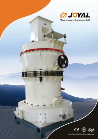
High-pressure Suspension Mill
>> Http://www.joyalcrusher.com
Shanghai Joyal Mining Machinery Co., Ltd
Grinding
● Application
The machine is mainly applied for the powder processing of mineral products in the industries of metallurgy, construction materials,
chemical, and mining, etc. It can produce powder from various non-flammable and non-explosive mineral materials with Mohs
hardness below 9.3 and humidity less than 6%, such as quartz, feldspar, calcite, talcum, barite, fluorite, cinder, cement clinker,
activated carbon, dolomite, granite, soft coal, coking coal, lignite, magnesia, chromium oxide green, gold ore, red clay, clay, bolus
alba, coke, coal Gangue, porcelain clay, kyanite, flour-spar, bentonite, medicinal stone liparite, diabase, pyrophyllite, shale red
stone, emeraldite, basalt, gypsum, graphite, carborundum, heat insulating material, etc.
3. High-pressure Suspension Mill
>> E-Mail:joyal@crusherinc.com
● Features
Compared with the common 5R4119 Raymond Mill under the same power
conditions, the output of the machine is increased by 10%. Under the
performance of high-pressure springs, the rollers grinding pressure on raw
materials can be raised by 1500kgf.
All the mineral materials with Mohs hardness below 9.3 can be crushed.
The finished powder size ranges from the maximum particle diameter of
0.613mm (30mesh) to the finest diameter of 0.033 mm (425 mesh). A few
materials can-reach 0.013mm (1000 mesh).
Its dust-removing effect exactly meets the National Dust Discharge Standard.
The classifier is easy for adjustment.
The grinding device adopts a superposition multi-grade sealing with good
sealing performance.
Grinding Plant
>> Http://www.joyalcrusher.com
4. Working Principle
1.
>> E-Mail:joyal@crusherinc.com
>> Http://www.joyalcrusher.com
The whole operating process of the mill(the crushing process of raw material
)is illustrated as follows:the agglomerate material is firstly crushed by the jaw
crusher into the required particle size; Then the crushed material is transferred
to a hopper by the elevator and fed uniformly, quantitatively and continuously by
the vibration feeder into the grinding chamber of the main frame for pulverizing.
The pulverized particles are brought up by the air current of the blower into the
classifier for classification. The particles with the required fineness are brought
up by the air current through the pipes into a cyclone collector for separation
and collection and the finished particles are discharged from a pipe outlet. The
air current is inhaled into the blower through the return pipe on the top of the
cyclone collector. The air current of the whole system is in a sealed circulation
under the condition of the positive and negative pressure.
3.
The main unit runs with a central shaft that is driven by a
transmission device.The top of the shaft is connected
with a quincunx stand, on which a grinding roller is
installed to form a swing support. The grinding roller not
only rotates around the center and the grinding ring, but
also rotates around its own axis due to the friction.
2.
Due to some moisture contained in the material to be
pulverized in a grinding chamber, the heat resulting from
grinding leads to the vaporized air which changes the airflow
volume. Moreover, the outside air inhaled from the narrow
gaps of the piping connections can increase the volume of air
current. Therefore, it is necessary to adjust the redundant air
pipe between the blower and the main unit for keeping the
balance of the air current. The redundant air is then guided into
a cloth bag of a dust cleaner to collect the fine powder in the
air. And the redundant air is discharged after purification.
5. Working Principle
4.
>> E-Mail:joyal@crusherinc.com
>> Http://www.joyalcrusher.com
The classifier performs the function of classifying the particles by the rotation of blades on the disk
driven by a speed-adjustable motor. The rotation speed of the blades is regulated according to the
particle size of the finished powder. In order to realize a finer particle size, the rotation speed
should be raised up to increase the contact between the blades and powder particles. The powder
particles that do not meet the requirement are thrown by the blades to the outer wall and separated
from the air current. The coarse particles drop because of self-gravity into the grinding chamber for
regrinding. The qualified particles go through the blades and are inhaled by the air current into the
cyclone collector. Then the particles are separated from the air current and collected.
5.
The cyclone collector plays an important role in the performance of the mill. When the air current
with the powder enters the collector, it is at a high speed of rotation. After the air current is
separated form particles, and when the air current concentrates towards the center along the cone
wall and moves to the bottom of the cone (the natural length of the air current),an upward rotating
air column is formed. Meanwhile, the particles are separated and fall down for collection. Because
the core of the upward rotating air current is in state of negative pressure, the lower part of the
collector must meet a very strict requirement of sealing and be isolated entirely from the outside
air. Otherwise, the collected particles will be taken away by the central air current, which will
directly influence the output of the complete system. Therefore, a powder-locking unit is installed
under the collector. Its function is to isolate the outside positive pressure air from the negative
pressure air inside the collector. This is a very important component. If the powder-locking unit is
not installed, or the powder-locking unit has not strict sealing, the output of the complete system
will be seriously influenced with no or less production of the finished powder.
6. Main Specifications
Grin d in g R o lle r
Item
Model
N u m b e rs D ia m e t e r
(p cs)
(m m )
H e ig h t
(m m )
>> E-Mail:joyal@crusherinc.com
Grin d in g R in g
Ou tsid e H e ig h t
D ia m e te r (m m )
(m m )
F e e d in g
S ize
(m m )
>> Http://www.joyalcrusher.com
Ou t p u t
S ize
(m m )
C a p a cit y
(t / h )
M otor
Power
(kw )
Ove ra ll
D im e n sio n
(m m )
YGM75
3
260
150
865
150
<15
0.613- 0.033 0.4-3.1
35.7
5000×4100×4850
YGM85
3
270
140
907
140
<20
0.613- 0.033 0.5-4.0
42.7
5150×5000×5200
YGM95
4
310
170
1050
170
<25
0.613- 0.033 1.1-5.6
72.5
7550×7400×8100
YGM130
5
410
210
1400
210
<30
0.613- 0.033 2.2-9.5 157.5
8510×8000×9645
YGM160
6
440
270
1740
270
<35
0.613- 0.033
12550×5700×8355
8-22
253
Whole System
■■■
The whole system of YGM130 high-pressure mill
consists of main frame, reducer, classifier piping
device, blower, jaw crusher, dustpan elevator,
electromagnetic vibration feeder, and electric switch
box motor etc. (For details, please refer to the
Installation Foundation Diagram).
7. Features of Whole System
>> E-Mail:joyal@crusherinc.com
>> Http://www.joyalcrusher.com
8. Features of Whole System
>> E-Mail:joyal@crusherinc.com
1. The whole mill is of a standing structure. It features of small occupying space
and strong integration capability. It can form up an independent production system
from lump materials crushing to finished powder and packaging.
2. All the finished particles produced by the mill have a good uniformity of
fineness. 98% of the particles can meet the required fineness and go through the
sieve, i.e. the passing rate is 98%. This is the advantage that other power grinding
equipment cannot exceed.
3. The transmission device of the main unit is equipped with a closed gearbox that
runs smoothly and reliable. The key components of the mill are made of best
quality steel, so the whole system is durable, stable and reliable.
4. The electrical system of the mill is centrally controlled and the advanced model
is rationally selected with high automation. Basically, an unmanned operation can
be realized in the pulverizing workshop. The light weight and compact vibration
feeder can feed the material uniformly. It is easily adjustable, energy saving and
convenient for operation and maintenance.
Grinding Plant
>> Http://www.joyalcrusher.com
9. Specification & Performance
(To refer to diagram 1 & 2)
(Diagram 1)
Basic Units
Motor of main unit
Motor of classifier
Motor of elevator
Motor of blower
Motor of jaw crusher
Electromagnetic vibration feeder
Unit
Model
Power
Rotating
Model
Power
Rotating
Model
Power
Rotating
Model
Power
Rotating
Model
Power
Rotating
Model
Power
kw
r/min
kw
r/min
kw
r/min
kw
r/min
kw
r/min
kw
Specifications & Technical Parameters
Y280S-4
75
1480
YCT200-4B
7.5
125-1250
Y100L2-4
3
1430
Y280S—4
75
1480
PE 250×400
15
970
GZ2F
150
Note: the crusher is optional according to different situations, such as the hardness of material, feeding quantity and etc.
Features of Whole System
>> E-Mail:joyal@crusherinc.com
(Diagram 1)
Name
Quantity of grinding rollers
Grinding roller, diameter × height
Grinding ring, diameter × height
Rotation speed of the main frame
Max. Feeding size
Product fineness
Capacity
Overall dimension: L×W×H
Unit
piece
mm
mm
r/min
mm
mm
t/h
mm
Specifications
5
410×210
1280×210
103
30
0.613-0.033
2.2-9.5
8510×8000×9645
>> Http://www.joyalcrusher.com
10. The Operation Rules of the Mill
>> E-Mail:joyal@crusherinc.com
>> Http://www.joyalcrusher.com
START Engine:
.........................................................................................................................................................................................
Before the powder grinding is started, check if all the maintenance doors are closed tightly and the
gap between jaw plates of the crusher accord to the particle size of the feeding material., and the
rotating speed of the classifier shall be adjusted in conformity of the required fineness of the
finished powder. At last, turn on the machine according to the sequence below:
1. Turn on the dustpan elevator; 2. Turn on the jaw crusher; 3. Turn on the classifier after the
hopper was fed with materials; 4. Turn on the blower (It starts with no load. You can load when the
blower runs normally); 5. Turn on the main frame. And immediately turn on the electromagnetic
vibrating feeder, after that, the powder grinding is started. The sequence of operation is outlined as
follows:
Start elevator
crusher
classifier
blower
main frame
feeder
TURN OFF Engine:
.........................................................................................................................................................................................
Turn off the machine in the following sequence:
1.Turn off the feeder and stop feeding materials;
2.Turn off the main frame in one machine;
3.Turn off the blower after blowing off all the residual particles;
4.Turn off the classifier finally.
The sequence of turning off the machine is outlined as follows:
Feeder
main frame
blower
classifier
Note: The material transported to the hopper by an elevator. When the material in the hopper reaches a certain quantity, stop the crusher first
and then the elevator. This operation depends on the quantity of the stored material
5.In order to guarantee the production safety, the mill must not be lubricated during the normal
operation. If any part of the machines generates abnormal noises, or the load is suddenly raised
up, turn off the machine immediately for checking and troubleshooting to prevent serious accidents.
Before restarting the machine, take out the residual material first. Otherwise, the current will
become strong as to affect the startup operation.
11. The Lubricating System
>> E-Mail:joyal@crusherinc.com
>> Http://www.joyalcrusher.com
■ The Lubricating System
..................................................................................................................................................................
In order to ensure the normal operation of the whole system, please
lubricate the machine according to the following instructions. Meanwhile
pay attention to changes in gear box of oil, turbine oil tank height, that is,
oil-soaked worm gear not less than 1 / 2. The oil height of reducer is not
less than 300 mm from the bottom up. The height of oil pools on the oil
standard of classifier is not less than 80 mm. Lubricating parts and oil
names are stated in the following table:
■ The List of Lubricating System
............................................................................................................................................................................................................
Lubricating Parts
Lubrication Form
Manual Oil tank
Name of Lubricating Oil
Lubricating
Points
Interval of
lubrication
Remarks
Replaced by calcium based grease
Central shaft of
the main frame
√
No. 3 MOS2 compound calcium based grease
2
1-3 days
Grinding rollers
√
No.3 MOS2 compound calcium based grease
10
2shifts
Replaced by calcium based grease
Bearing base of blower
√
No.3 MOS2 compound calcium based grease
2
1 month
Replaced by calcium based grease
Bearing base of classifier
√
No.3 MOS2 compound calcium based grease
2
Half a month
Replaced by calcium based grease
Bearing base of elevator
√
No.3 MOS2 compound calcium based grease
2
1 month
Replaced by calcium based grease
Keeping the oil level Changing oil once every three months
Turbine box of elevator
√
HJ-4 machine oil
1
Reducer
√
HJ-4 machine oil
3000hours
Maintenance, cleaning, oil changes
Oil Pool of classifier
√
HJ-4 machine oil
3000hours
Maintenance, cleaning, oil changes
12. The Electrical Control System
>> E-Mail:joyal@crusherinc.com
>> Http://www.joyalcrusher.com
■ The List of Lubricating System
.......................................................................................................................................................................................................
The motor control system of the mill is centralized in the
controlling cabinet. Every unit shall be started sequentially in
accordance with the operation procedure and rules. In this control
cabinet, most of the motors are generally asynchronous motors
except classifier and feeder.
1. The starting of the main unit and blower
In this control system, the reduced voltage start is used for the
motor with the power over 30KW while the direct start is for that
below 30KW. In this system, blower with star delta starter, the
main unit is used to start the Yanbian triangle.
The star delta starter is connected with normal operation. The
control ircuit is composed of contactor and time relay. In an automatic switching, the customer can make adjustment
according to the start. The time relay is usually set with an extension of over 6 seconds, which can be also adjusted by the
customer.
2. The control and automatic feeding of the vibrating feeder
The structure of electric-magnetic vibrating feeder is a two particle fixed-directional forced vibration system. It consists of a
feeding channel connected with a fork armature. It hangs under the material tank and with some free moving space. It cannot
be blocked and bumped by other objects to avoid noises during the operation.
(1) After installation of the electro-magnetic vibrating feeder, loose the screws (upper three and lower one) on a positioning
connection fork. After loosing the screws, fix the nuts, open the rear cover of the vibration feeder, and check if the gap
between iron core and gap bit is within 1.8-2.1mm.The two parts should be parallel and clean. All the screws should be
screw down firmly. Finally, put on the cover and fix it.
(2) No-load trial run with power on. Adjust the amplitude resistor R1 in the electrical control cabinet slowly from small to big
with the amplitude ranging within 1.8-2.5mm and the current of 1.2A.Keep running for several hours to see if the amplitude
current is stable. If it is normal, open the door of material tank for material feeding and check if the current of feeding material
is stable. The amplitude is allowed to fall down 0.5 mm. If the amplitude current is at the rated value but cannot meet the
requirement of the feeding capacity, hang the vibrator at a 20 decline position to meet the feeding requirement.
3. Control of Classifier
JDLA buncher transmission is used for the classifier. The control is carried out by the bottom of the electro-magnetic slide
controller on the control cabinet. When the button is pressed, the squirrel-cage motor will be started first. Then close the slide
power switch and turn the knob of rotating speed to make the classifier to reach the speed that matches the required
fineness (powder particle size). The powder fineness can be controlled in this way.
13. Repair & Maintenance
>> E-Mail:joyal@crusherinc.com
>> Http://www.joyalcrusher.com
1.During the application of the mill, some personnel shall be arranged to take responsibility of management.
The operators must be qualified with the required technical knowledge. Before the installation of the mill, the
persons related to the operation should receive technical training and fully understand the operating
principle, performance and regulations of the pulverizer.
2.In order to guarantee the mill in a normal working state, a Safety Operation System for the Maintenance of
the equipment must be established. Only in this way can the pulverizer be guaranteed to have a long-term
and safe operation. Meanwhile, it is necessary to have the required repairing tools, lubricant and grease,
spare parts and accessories.
3.After some period of running, the mill should receive an examination and repairing. The components
vulnerable to worn out, such as grinding roller, grinding ring, relieving tool etc. should be repaired or
replaced. Before and after the operation, a careful examination should be carried out for the connecting
screws, bolts and nuts on the grinding rollers so as to find whether they are loose or sufficiently lubricated.
4.The grinding rollers should be replaced when roller device works more than 500 hours. When replacing
grinding rollers, all the rolling bearings in the roller sleeves must be cleaned, and the damaged parts should
be replaced. Powerful injector and grease gun can be as oiling tool.
14. >> E-Mail:joyal@crusherinc.com
>> Http://www.joyalcrusher.com
The Model Number of All the Bearings and Name and
Quantity of the Quick-wear Parts.
For the mill and wearing parts, you can refer to these two tables in order that the customer can select them conveniently.
Table of Rolling Bearings
No.
Bearing Type
Specifications(mm)
Quantity
Relevant unit
1
2234
170×310×52
1
Up the main frame
2
3526
130×230×64
1
Down the main frame
3
8332
160×270×87
1
At the bottom of the main frame
4
7617
85×180×64
1
Decelerator
5
53618
90×190×64
1
Decelerator
6
7620
100×215×78
2
Decelerator
7
7626
130×280×99.5
2
Decelerator
8
7616
80×170×62
5
Above the grinding roller
9
3620
100×215×73
5
Below the grinding roller
10
310
50×110×27
1
Inside of the classifier
11
111311
55×120×29
1
Outside of the classifier
12
7315
75×160×40.5
1
Above the classifier
13
7312
60×130×34
1
Below the classifier
14
6308
40×90×23
4
Dustpan elevator
15
7208
40×80×20
2
Dustpan elevator Turbine decelerator
16
6208
40×80×18
2
Dustpan elevator Turbine decelerator
17
3616
80×170×58
2
Blower
15. >> E-Mail:joyal@crusherinc.com
>> Http://www.joyalcrusher.com
The Model Number of All the Bearings and Name and
Quantity of the Quick-wear Parts.
For the mill and wearing parts, you can refer to these two tables in order that the customer can select them conveniently.
Table wearing Parts
No.
Name
Quantity
Material
Specifications
1
Liner
1
HT200
2
Dowel pin
12
MC Nylon 60
�56
3
Dowel pin
12
MC Nylon 60
�30
4
Spade
5
Welded with armor plate
5
Spade base
5
ZG35
6
Grinding roller device
5
Assembly
7
Rubber sleeve
10
Special rubber
8
Grinding roller
5
ZG65Mn
9
Grinding roller shaft
5
No. 45 steel
10
Crosspiece shaft
5
No. 45 steel
11
Grinding ring
1
ZG65Mn
12
Blower vane
6
Wearable armor plate
13
Spade with bottom plate
1
ZG35
14
Oil seal of framework
2
Top of main shaft
15
Bottom end cover of grinding roller
5
ZG35
16
Oil seal of framework
2
Bottom of main shaft
130×160×15
17
Oil seal of framework
5
Grinding roller grade 3
115×150×14
18
Oil seal of framework
10
Grinding roller grade 2
115×150×14
19
Sealing ring
5
Industry wool felt
20
Blade of classifier
60
Wearable armor plate
21
Wind guard board
12
Wearable armor plate
22
Wedge shaped belt
6
C-3150
23
Wedge shaped belt
4
B-3150
190×240×18