IRJET- Computational Fluid Dynamic Analysis of Performance of Centrifugal Pum...
10-P3-265
1. Introduction
Low temperature facility of Tata Institute of
Fundamental Research Mumbai provides liquid
helium and nitrogen along with the various support
services to many facilities and laboratories of the
institute. Liquid nitrogen is produced by STIRLIN-8
plant with liquefaction rate of 110 liter per hour at
an elevated pressure of 2bar. The vacuum jacketed
and super-insulated liquid nitrogen transfer line of
about 310 meters long interconnects plant and SC
LINAC accelerators. The resent operations of the
system is providing results far from desired. The
failure of the current system in achieving this goal
is the primary reason for the investigations and
discussions.
layout of LN2 transfer line at tifr
Heat in leak calculations
Three major sources of heat inleak into the
transfer line are
Heat inleak through spacers
Q = 199.495 Watts
Radiation heat inleak
Where Fe is shape factor
N is number of shields
Q = 7.75Watts
Heat inleak through bayonet joint
Standard heat in leak for a byonet joint for 1/2”
inner diameter is 1.9watts,
So , Q = 121.6watts
.
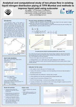
Pressure drop calculations and findings
Separation model for calculation of pressure drop has been found to be most suitable for liquid
nitrogen hence using same following calculations were made
The parameters used in correlating adiabatic two phase frictional pressure drop data according to the
Lockhart Martinelli seperation model are as follows:
=
Two phase pressure drop for maximum possible inlet pressure 4 bar
It is evident from the pressure drop analysis that with the change in diameter of the line the desirable
pressure drop limit can be easily achieved and thus affecting the performance of the system. But our
site at TIFR Mumbai has following constrains:-
Pressure at the supply source cannot be more than 4 bar
Changing diameter is not a viable option as the system already exits with 15NB line
Owing to these constrains in order to get best possible liquid yield the most suitable solution is liquid
nitrogen subcooler
Subcooler for the system
Inlet condition is fixed at 2bar and x=0.25 for better results
Location of the subcooler accordingly can be fixed depending on the pressure drop and quality of
the fluid at particular point
Pool boiling outside and condensation inside the tube is assumed
All the calculations have been done assuming fully developed boundary layer
Length of the coil is the function of diameter of coil
Boil off of the liquid nitrogen is calculated and accordingly refill schedule is fixed
Assuming coil diameter same as transfer line that is 0.017m the coil length is worked out to be 25m
and the pressure drop across the subcooler is 0.0166bar
S S Jadhav 1, K V Srinivasan2 S M lawankar 3
1,3Government College of engineering, Amravati
2 Tata institute of fundamental research, Mumbai
jadhav.sanket20@gmail.com
Result and conclusion
The pressure drop and heat load
calculations have been done for the
existing system.
Pressure drop across the transfer line is
the function of diameter and as it is a
constrain nothing can be done about it
To improve the liquid yield a helical
coil in bath type subcooler is proposed.
Location of the subcooler is derived in
such a way that conditions at the inlet
of the subcooler are such that
maximum efficiency is achieved
Future work
Software validation of the subcooler
design
Study of different geometries of coil
and its effect on the performance of
subcooler
Analytical and computational study of two phase flow in existing
liquid nitrogen distribution piping at TIFR Mumbai and methods to
improve liquid yield using subcooler
0
1
2
3
4
5
6
7
8
9
15 30 45 60 75 90 105 120 135 150 165 180 195 210 225 240 255 270 285 300
pressuredropinbar
length in meters
line diameter=15NB
outlet quality 0.2
outlet quality 0.3
outlet quality 0.4
outlet quality 0.5
outlet quality 0.6
0
0.2
0.4
0.6
0.8
1
1.2
1.4
15 30 45 60 75 90 105 120 135 150 165 180 195 210 225 240 255 270 285 300
pressuredropinbar
length in meters
line diameter=25NB
outlet quality 0.2
outlet quality 0.3
outlet quality 0.4
outlet quality 0.5
outlet quality 0.6