Tip edge applaince
•
4 likes•509 views

The Indian Dental Academy is the Leader in continuing dental education , training dentists in all aspects of dentistry and offering a wide range of dental certified courses in different formats.for more details please visit www.indiandentalacademy.com

Recommended
Recommended
More Related Content
What's hot
What's hot (20)
Viewers also liked
Viewers also liked (8)
Similar to Tip edge applaince
Similar to Tip edge applaince (20)
More from Indian dental academy
More from Indian dental academy (20)
Recently uploaded
Recently uploaded (20)
Tip edge applaince
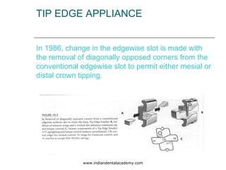
- 1. TIP EDGE APPLIANCE In 1986, change in the edgewise slot is made with the removal of diagonally opposed corners from the conventional edgewise slot to permit either mesial or distal crown tipping. www.indiandentalacademy.com
- 2. Such modifications of the slot could not have been considered by ANGLE, because at that time there were no mesiodistal uprighting springs. These springs were created by DR BEGG in 1960, to upright teeth in conjunction with ribbon arch type brackets. Without such springs the Tip-Edge bracket itself would not be practical. www.indiandentalacademy.com
- 4. VARIOUS ADVANTAGES OF TIP EDGE SLOT Not only does it facilitate space opening or closing, it also enhances retraction of the buccal segments of one arch and automatically, through intermaxillary elastics, creates anchorage in the other. Facilitates intrusion of teeth for anterior bite opening. www.indiandentalacademy.com
- 5. Archwire slots, that open or close during treatment, for maximum ease of archwire changes and minimal patient discomfort. The ability to torque and upright teeth from forces generated by auxiliaries, which leaves the stiffer arch wires relatively undisturbed and provides stability and molar control. www.indiandentalacademy.com
- 6. These new archwire slots have in / out compensations and are preadjusted to automatically achieve desired degrees of crown tip and root torque with little or no modifications to the arch wires themselves. www.indiandentalacademy.com
- 7. Because the arch wire slot permits initial crown tipping mesially or distally and faces horizontally, the slot and bracket are termed TIP EDGE. The technique, which take full advantage of this slot and differential tooth movement with straight archwire, is termed the DIFFERENTIAL STRAIGHT-ARCH TECHNIQUE (D S A T). www.indiandentalacademy.com
- 8. APPLIANCES TIP EDGE BRACKETS By removing predetermined, diagonally opposed corners from the conventional edgewise archwire slot, the Tip-Edge bracket is created. This permits the desired distal crown tipping required for differential tooth movement. Preadjusted in three dimensions the Tip-Edge slot permits the use of straight arch wires in the majority of cases, both extraction and non extraction. www.indiandentalacademy.com
- 9. The slot is designed so that initial second order changes, mesiodistal crown tipping, can be accomplished in the presence of a straight round archwire and powered by light intra oral forces---elastics and coil springs. www.indiandentalacademy.com
- 10. Forces for subsequent root uprighting, tip and/or torque are generated by auxiliaries and not by flexing the arch wires. This simplifies the treatment through the use of “straight” arch wires while providing increased range of root movement, from physiologic forces with maximum stability and comfort. www.indiandentalacademy.com
- 11. Brackets are available in single , twin and ceramic forms. www.indiandentalacademy.com
- 12. Not only do the archwire slots permit initial crown tipping but also they are preadjusted to provide the desired final degrees of crown tip and torque. www.indiandentalacademy.com
- 13. MOLAR TUBES To maximize the advantages inherent in differential tooth movement, it is advantageous to utilize relatively long and loose fitting molar tubes in the early stages of treatment and shorter , rectangular tubes in the final stage. Therefore tip-edge tubes are of double configuration. The longer round tube is positioned gingivally and the shorter rectangular tubes occulasally. www.indiandentalacademy.com
- 15. ARCH WIRES Initial arch wires are formed of high tensile 0.016 inch round stainless steel. These wires will be able to overcome anterior vertical force vectors from class II or class III intermaxillary elastics to permit simultaneous bite opening and antero-posterior interarch changes. www.indiandentalacademy.com
- 16. Arch wires of 0.014 inch or 0.016 inch Ni-Ti can be used for initial alignment in class I crowded cases. Rectangular 0.0215 x 0.028 inch stainless steel arch wires should be preferred for final finishing. www.indiandentalacademy.com
- 17. AUXILLARIES Due to generous size of the vertical slot in T E bracket many auxiliaries are used through out treatment. Power pins for elastomerics. Rotating springs. Side winder springs. Ni-ti torque bars. Single tooth torquing auxiliaries www.indiandentalacademy.com
- 18. POWER PINS Used to accept elastomerics or rotating springs for rapid, physiologic rotation. www.indiandentalacademy.com
- 19. MESIO-DISTAL UPRIGHTING SPRINGS OR SIDE WINDERS They provide localized tip control of individual teeth without arch wire modifications. When finishing with rectangular arch wires, they can produce the desired final axial inclination for all teeth including torque. www.indiandentalacademy.com
- 20. Sectional wires of Ni-Ti are used for one or two appointments for initial alignment or the eruption of the impacted teeth. When using round arch wires, anterior root torque can be achieved by Ni-Ti Torque bars placed in deep grooves of central and lateral incisor brackets. The torquing of a single tooth is rapidly accomplished with an Individual Root Torquing Auxiliary. www.indiandentalacademy.com
- 22. CONCEPT AND FUNCTION The Tip-Edge concept is to provide an edgwewise type bracket that is familiar to all orthodontists and can be used in the simplest manner to treat all malocclusions through differential tooth movement. This is accomplished by maintaining everything that is positively associated with an edgewise bracket, while removing diagonally opposed corners of the slot which prevents mesiodistal crown tipping. www.indiandentalacademy.com
- 23. This than provides an edgewise bracket that enhances rather than hinders bite opening, class II or III correction and the closing of posterior spaces. Tip and torque control are delayed until the end of the treatment and than easily achieved utilizing root moving forces that are relatively light, long lasting and generated by auxiliaries and not by flexing the main arch wire. www.indiandentalacademy.com
- 24. BITE OPENING Most malocclusions require anterior bite opening, which involves the intrusion of incisor teeth. If each tooth is free to intrude along its own path of least resistance, desired bite opening can be accomplished relatively rapidly and with the lightest of forces--------approx 5 gm per tooth. www.indiandentalacademy.com
- 25. Conventional edgewise slots prevent this free root movement and when teeth are tipped mesially or distally can even cause lateral movement of roots to further complicate the intrusion. Tip-edge archwire slots with their one point contact with the archwire prevents the creations of such lateral pressures and permits the roots to intrude in an unhindered fashion. www.indiandentalacademy.com
- 27. Because of this one point contact between the archwire and the bracket slot, it is possible to open the deepest of anterior bites without the need for extra oral forces. The principle of differential forces and mechanics are applied through high tensile stainless steel archwires(0.016 inch), light intermaxillary elastics and to some extent, the forces of mastication. www.indiandentalacademy.com
- 28. RETRACTION AND SPACE CLOSURE WITHOUT LOSS OF VERTICAL CONTROL All teeth tend to tip distally as they are retracted. With conventional archwire slot it first causes binding between the slots and the wire and second, the incisal deflection of arch wire itself especially in canine region. The central and lateral incisors are than extruded which deepens the bite or increases gingival display. www.indiandentalacademy.com
- 29. Because the appropriate corners have been removed in Tip-edge archwire slots, there is no binding and no deflection. www.indiandentalacademy.com
- 30. VARIABLE ANCHORAGE SLOT Not only are Tip-edge archwire slots designed to permit crown tipping in one direction but they also become larger as the teeth tips. www.indiandentalacademy.com
- 31. The advantages gained by this increase in archwire slot relative to arch wire include No binding or archwire deflection during retraction. Ease of stepping up in archwire size. No inadvertent mesial or distal root movements www.indiandentalacademy.com
- 32. Ease of placing rectangular arch wires when third order discrepancies exist between the slots and the wires. No need to use Ni-Ti or memory wires to avoid discomfort and/or accidental debonding. www.indiandentalacademy.com
- 33. ANCHORAGE CONSIDERATIONS Extra oral anchorage is absolutely not needed with DSAT with tip-edge brackets as the forces are so light (2 oz) that adequate anchorage can easily be found within the mouth. www.indiandentalacademy.com
- 34. Binding, which normally occurs between conventional edgewise slots and archwires during space closure is nonexistent because the corners of the slots which press against the upper and lower surfaces of the archwires during tipping and which causes about 90% of the friction from an edgewise appliance are gone. www.indiandentalacademy.com
- 35. Furthermore in the DSAT the archwires move distally with the anterior teeth during space closure and premolars are usually not bracketed. So there is no sliding friction between archwires and brackets or ligatures to produce any additional strain on anchorage. www.indiandentalacademy.com
- 36. The only source of sliding friction is within the molar tubes and is at the absolute minimum because the molars are held upright, the tubes are relatively long, large in diameter and of course, there is no ligatures. www.indiandentalacademy.com
- 37. DIFFERENTIAL STRAIGHT ARCH TECHNIQUE The DSAT takes full advantage of TE brackets. This makes possible the successful treatment of even the most severe of malocclusions with a minimal number of appointments and archwires. Treatment is divided into three stages. Each stage features a distinct set of treatment goals that must be achieved before moving on to the next. Specific archwires, elastics and auxillaries are used for that particular stage and mixing them will lead to undesirable results. www.indiandentalacademy.com
- 38. STAGE 1 This stage is the only stage of DSAT treatment where arch wires are used to directly generate tooth moving forces ( anterior alignment and bite opening ). During the rest of the treatment they serve to preserve the vertical and lateral dimensions , while auxillaries are used to produce all individual movement. www.indiandentalacademy.com
- 39. GOALS OF STAGE I Vertical correction of deep or open anterior bite. Horizontal correction of anterior over or under jet. Align anterior teeth to eliminate crowding or spacing www.indiandentalacademy.com
- 40. BITE OPENING MECHANICS Opening the bite is the most important goal of stage 1 The rapid correction of a deep anterior overbite to an edge to edge incisal relationship allows for the full expression of any potential benefits of mandibular growth in the correction of a class II malocclusion. www.indiandentalacademy.com
- 41. OVERJET/UNDERJET CORRECTION The correction of overjet or underjet is accomplished simultaneously along with anterior vertical discrepancies. It is accomplished through the use of either class II or III elastics depending on the incisar relationships. www.indiandentalacademy.com
- 42. ANTERIOR ALIGNMENT When space is available distal to canines, anterior alignment is achieved using elastomeric ties to the archwire through the vertical slots of the Tip-Edge brackets. The Tip-edge archwire slots allow adjacent teeth to simply tip out of the way as the lingually displaced teeth are brought into position. www.indiandentalacademy.com
- 43. When moderate to severe crowding is present at the start of non extraction treatment, vertical loops are employed in the anterior segments of the 0.016 inch archwire. www.indiandentalacademy.com
- 44. Rotated teeth are corrected using rotating springs inserted through the vertical slots of the brackets. www.indiandentalacademy.com
- 45. These auxilaries are available in either clockwise or counter clockwise versions. The tooth is viewed from the occlusal to determine the desired direction of rotation and the corresponding spring is selected, then engaged. Rotations are overcorrected whenever possible and held in these positions throughout the treatment using either overrotation brackets for incisors or through mesiodistally offset bonding positions on canines and premolars. www.indiandentalacademy.com
- 46. STAGE 2 Stage 2 is the shortest of the three stages of Tip-Edge treatment usually being completed in 2 to 3 appointments. The primary goal of stage 2 is the closing of posterior spaces. In this other than horizontal elastics to close spaces, class II or class III elastics are given to maintain desires anterior tooth relation. www.indiandentalacademy.com
- 47. GOALS OF STAGE II Close remaining posterior spaces Correct or maintain dental midline. Correct posterior cross bite. Achieve class I molar relations. Over rotate severely rotated premolars. Level anchor molars. Maintain all corrections achieved during stage I. www.indiandentalacademy.com
- 48. STAGE 2 MECHANICS AND ARCHWIRES Far less archwire manipulation is required during stage 2 because the archwires serve only to maintain the vertical and lateral corrections achieved during stage 1. High tensile, round 0.022 inch stainless steel wire should be used for this. www.indiandentalacademy.com
- 49. In mild to moderate anchorage situations the archwires are engaged through the occlusal, rectangular molar tubes. This levels the premolar brackets and molar tubes early in treatment, easing the transition to stage 3. In maximum anchorage situations where friction between the tubes is more of a concern, it is preferred to insert the archwires through the larger diameter gingival round tubes. www.indiandentalacademy.com
- 50. STAGE 2 BRAKING MECHANICS During stage 2 positive measures are sometimes necessary to correct an abundance of available space which can be caused naturally by congenitally missing or relatively small teeth or by extraction of teeth in borderline extraction cases. Whatever the reason, corrective measures are required to prevent overretraction of the anterior teeth. www.indiandentalacademy.com
- 51. Through the application of mechanical brakes (side winder springs on premolars, canines and incisors, in conjunction with 0.022 inch round or 0.0215 x 0.028 inch rectangular wire), anterior teeth are prevented from further unrestricted distal and/or lingual crown tipping. Relatively heavy horizontal forces (6-8 oz) are than applied between these newly created anterior resistance units and the posterior teeth. www.indiandentalacademy.com
- 52. STAGE 3 GOALS OF STAGE III Achieve final axial inclination of all teeth. Maintain all corrections achieved during stages I and II. This is the longest stage of DSAT , usually taking about half the total treatment time. Amount of time varies , but in an extraction case anywhere between 9-12 months. www.indiandentalacademy.com
- 53. All uprighting and torquing is accomplished by auxillaries. The same stage II archwire can be used in stage III. All uprighting movements are self limiting as each tooth reaches its final mesiodistal inclination , the uprighting surface of the tip edge arch wire slot contacts the arch wire preventing over uprighting. When using rectangular arch wire the torquing as well as uprighting is self limiting www.indiandentalacademy.com
- 54. STAGE 3 AUXILIARIES All individual tooth movements during stage 3 are accomplished using auxiliaries. To produce mesiodistal uprighting , side-winder springs are employed. www.indiandentalacademy.com
- 55. These springs have several advantages over conventional uprighting springs More efficient since coil located over wire. More esthetic and hygienic as it lies over the bracket. www.indiandentalacademy.com
- 56. The labial surface of each tooth is evaluated to determine which manner of uprighting is desired, clockwise or counterclockwise. Once it is determined, the appropriate side-winder uprighting spring is selected and engaged into the vertical slot of the bracket. www.indiandentalacademy.com
- 57. Although side winder uprighting springs can be inserted into the bracket from either the gingival or incisal, they are normally engaged from the incisal to prevent coil distortion from occlusal forces. www.indiandentalacademy.com
- 58. TORQUING AUXILIARIES Torquing of the maxillary incisor roots palatally can be accomplished using one of several types of torquing auxiliaries. The most commonly employed torquing auxiliaries are nickel titanium Torque Bars. These are curved ribbon arch sections of 0.022 x 0.018 inch Ni Ti formed with 30 degrees of torque. These auxiliaries are invisible when in place because they lie directly behind the main arch wire. www.indiandentalacademy.com
- 59. For the successful use of Torque Bars with the Tip-Edge appliance, special “deep grove” brackets are used on the maxillary incisors. These brackets feature conventional preadjusted edgewise archwire slots cast into the bottom of the Tip Edge archwire slots. www.indiandentalacademy.com
- 60. During stages 1 and 2, when a one point contact between archwire and slot is desired to facilitate bite opening and retraction, a cap fills the deep groove. At the beginning of stage 3 the cap is removed and the Torque Bar is ligated tightly into the deep groove under the round base archwire. www.indiandentalacademy.com
- 62. If torquing of an individual tooth is desired, an Individual Root Torquing auxiliary (IRT) is used. This auxiliary can deliver palatal or labial root torque depending upon the direction from which it is engaged into the brackets vertical slot. i.e. palatal root torque if engaged incisally and labial root torque ,if inserted gingivally. www.indiandentalacademy.com
- 63. ROUND OR RECTANGULAR WIRE IN STAGE 3 ? Continuing on round wire simplifies treatment for the operator. Also when molar torque is not required and torquing of the anteriors is required then a round wire with torque bar can be used along with side winder springs. If a 0.022 SS wire is used in stage III then a molar offset and mild bite opening curves should be incorporated and if class II elastics are being used , the lower arch wire width is increased by 2mm. www.indiandentalacademy.com
- 64. On the other hand generalized and individual torquing requirements are the strongest indications for utilizing rectangular arch wires in stage III. That would include torquing molars , canines and incisors. The other advantage of rectangular stage III arch wire along with side winder springs is that the 2nd order power delivered by the springs is translated by the internal geometry of the tip edge bracket into third order moments. The resulting forces are physiologic and stop when the teeth have reached predetermined inclination. www.indiandentalacademy.com