1. L.A.Abraham Arunchand, K.Sudharshan Reddy / International Journal of Engineering Research and
Applications (IJERA) ISSN: 2248-9622 www.ijera.com
Vol. 2, Issue 4, July-August 2012, pp.087-092
An Artificial-Intelligence Based Induction Motor Speed control and
Estimation using conventional MRAS with dynamic reference modal
L.A.Abraham Arunchand*, K.Sudharshan Reddy**,
*(PG student, Department of Electrical & Electronics Engineering, Sri Venkatesa Perumal College of Engineering &
Technology)
** (Assistant professor, Department of Electrical & Electronics Engineering, Sri Venkatesa Perumal College of Engineering &
Technology)
Abstract− The Model Reference Adaptive System based model. However, both the conventional MRAS and
(MRAS) is probably the most widely applied speed sensor AI-based MRAS scheme are easily affected by machine
less drive control scheme. This paper gives induction motor parameter variations, which happen during practical
speed estimation using conventional MRAS and AI-based operation. In this case, an online stator resistance estimator
MRAS with Stator Resistance Compensation methods. A is applied to the AI-based MRAS scheme which makes the
conventional mathematical model based MRAS speed whole scheme more robust during computer simulation and
estimation scheme can give a relatively precise speed could possible make the scheme usable for practical
estimation result, but errors will occur during low frequency operation. The comparison of schemes presented here is
operation. Furthermore, it is also very sensitive to machine felt to be valuable since much of the literature presents
parameter variations. However, an AI-based MRAS-based results for the novel approach alone.
system with a Stator Resistance Compensation model can
improve the speed estimation accuracy and is relatively II. SPEED ESTIMATION USING
robust to parameter variations even at an extremely low CONVENTIONAL MODAL REFERENCE
frequency. Simulation results using a validated machine ADAPTIVE SYSTEM
model are used to demonstrate the improved behavior and
also controlling the speed of motor by using space vector In MRAS, there are two models, which work parallel to
pulse width modulation (SVPWM) with estimated speed estimate flux-linkage of induction motor, first model name
taking as feedback. reference, and input is current and voltage, the output flux
linkage of this model is to be used fiducial variable. The
Index Terms− Dynamic Reference Model, Model second model is adaptive, input of it is current and rotor
Reference Adaptive System (MRAS), Neural Networks, speed, output flux-linkage of this model is been adjusted
Induction Motor Control. continuously in order that the error between those two
models is turn to zero by adjusting the input of adaptive
I. INTRODUCTION model through PI controller. The expressions for the rotor
flux linkages in the stationary reference frame can be
Much effort has been devoted to speed-sensor less obtained by using the stator voltage equations of the
induction machine drive schemes, with Model Reference induction machine (in the stationary reference frame).
Adaptive System (MRAS) being the most popular. In a These give (1) and (2), which are now rearranged for the
conventional mathematical-model-based MRAS, some rotor flux linkages:
state variables are estimated in a reference model, (e.g.
rotor flux linkage components, ψrd, ψrq, or back e.m.f. L L2 m
L
V r
ds
Rs ids dt ( Ls )isd
components, ed, eq,etc.) of the induction machine dr
m
Lr (1)
L V
obtained by using measured quantities, (e.g. stator currents L2 m
and perhaps voltages). These reference model components
r
qs
Rs iqs dt ( Ls )isQ (2)
are then compared with state Variables estimated using an L
qr
m
Lr
adaptive model. The difference between these state
variables is then used in an adaptation mechanism, which, These two equations represent a so-called stator voltage
for example, outputs the estimated value of the rotor speed model, which does not contain the rotor speed and is
(ωr) and adjusts the adaptive model until satisfactory therefore a reference model. However, when the rotor
performance is obtained Nevertheless, greater accuracy voltage equations of the induction machine are expressed
and robustness can be achieved, if the mathematical model in the stationary reference frame, they contain the rotor
is not used at all and instead, an AI-based non-linear fluxes and the speed as well. These are the equations of the
adaptive model is employed. It is then also possible to adaptive model:
eliminate the need of the separate PI controller, since this
can be integrated into the tuning mechanism of the AI-
87 | P a g e
2. L.A.Abraham Arunchand, K.Sudharshan Reddy / International Journal of Engineering Research and
Applications (IJERA) ISSN: 2248-9622 www.ijera.com
Vol. 2, Issue 4, July-August 2012, pp.087-092
ˆ 1
L i Tˆ ˆ dt
T
m ds
r r (3) different types of speed tuning signals. It is believed that
dr qr dr
r some of these solutions can give high accuracy and are
relatively robust to parameter variations even at extremely
ˆ 1
L i Tˆ ˆ dt low stator frequency. One specific implementation of the
T
m qs
r r (4) ANN-based MRAS speed estimator system which is
qr dr qr
r
popular in academic work, as shown in Fig. 2, which is
similar to the conventional MRAS system. In this new
The reference and adaptive models are used to estimate the model, the adaptive model is replaced by a simple two
rotor flux linkages and the angular difference of the layer neural network, which enables the whole system with
outputs of the two estimators fast response and better accuracy than the conventional
w Im( r , * r ) rq rd rd rq is
ˆ ˆ ˆ used as the MRAS
.
speed tuning signal. Adaptation mechanism is the PI
controller to turn the error state of reference and adaptive
model to zero by adjusting the input of adaptive model,
which variable is the rotor speed.
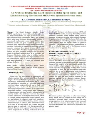
Fig.2 MRAS-based rotor speed estimator containing
a two layer ANN
Fig.1 MRAS-based rotor speed observer using rotor
IV. MRAS based Two Layer ANN speed estimator
flux with dynamic reference modal
Linkages for the speed tuning signal
Compared to the conventional MRAS based rotor
By the time error state equivalent to zero the system give speed estimator containing a Two layer ANN could give
the estimate speed equivalent to actual speed .The more accurate estimation result and relatively robust to
estimated speed can be expressed as (5) parameter variations. The two layer ANN replaces the
adjustable model and adaptive mechanism in the
r k p w ki w dt (5) conventional MRAS, but the reference model is still
necessary for estimation the rotor flux which is used as
III. ARTIFICIAL INTELLIGENCE-BASED speed tuning signal. Several machine parameters are used
to build the conventional reference model, such as stator
MODEL REFERENCE ADAPTIVE
resistance (Rs) and stator reluctance (Ls). These parameters
SYSTEM may change during the different periods of motor
operating. The values of these parameters are fixed in the
The MRAS-based schemes described in the previous reference model. So the ANN speed estimator is still
section contain a reference model and an adaptive model. sensitive to parameter variations especially during the
However, greater accuracy and robustness can be achieved motor low speed running period. To solve this problem and
if the mathematical model is partially replaced by a neural make this scheme more independent to the machine
network. It is then also possible to eliminate the need of the parameters, a stator resistance estimator is built in the new
separate PI controller, since this can be integrated into the reference model, in which the stator resistance Rs value
tuning mechanism of the neural network-based model. The could be estimated online. Fig. 3 shows the total scheme of
neural network-based model can take various forms: it can neural network based MRAS with a dynamic reference
be an artificial neural network (ANN) or a fuzzy neural model.
network etc. and there is also the possibility of using
88 | P a g e
3. L.A.Abraham Arunchand, K.Sudharshan Reddy / International Journal of Engineering Research and
Applications (IJERA) ISSN: 2248-9622 www.ijera.com
Vol. 2, Issue 4, July-August 2012, pp.087-092
In this new system, both the reference model and adaptive ANN, the sampled data forms of equations (3) and (4) are
model of the conventional MRAS system are modified for considered. By using the backward difference method, the
better performance. The whole system can be divided into sampled data forms of the equations for the rotor flux
two main parts, the dynamic reference model part and the linkages can be written as (8) and (9), where T is the
neural network part. The dynamic reference part consists sampling time.
of the dynamic reference model derived from equations (1)
and (2), in which the stator resistance Rs is replaced by the rd (k ) rd (k 1) rd(k 1) wr rq (k 1) Lm
isd (k 1)
online estimated value Rs coming from equation (6) and T Tr T Tr
(7), (8)
ˆ Ki
Rs ( K p )eR s (6)
P
rq (k ) rq (k 1) (k 1) wr rd (k 1) Lm
rRs isD ( rd rd ) isQ ( rq rq )
ˆ ˆ rq isq (k 1)
(7) T Tr T Tr
The neural network part contains a simple two-layer neural (9)
network, with only an input layer and an output layer.
Thus the rotor flux linkages at the kth sampling instant can
Adjustable and constant weights are built in the neural
be obtained from the previous (k-1)th values as
network, and the adjustable weights are proportional to the
rd (k ) rd (k 1)(1 T / Tr ) rT rq (k 1) ( LmT / Tr )isd (k 1)
rotor speed.
(10)
rq (k ) rq (k 1)(1 T / Tr ) rT rd (k 1) ( LmT / Tr )isQ (k 1)
(11)
Introducing the following weights are given:
w1 1 c
w2 r cTr r T (12)
w3 cLm
It can be seen that w1 and w3 are constant weights, but w2
Fig.3 MRAS based ANN speed estimator with dynamic is a variable weight and is proportional to the speed. Thus
reference model. Equations (10) and (11) take the following forms:
The adjustable weights are changed by using the error rd (k ) w1 rd (k 1) w2 rq (k 1) w3isD (k 1)
between the outputs of the reference model and the (13)
adjustable model, since any mismatch between the actual rq (k ) w1 rq (k 1) w2 rd (k 1) w3isQ (k 1)
rotor speed and the estimated rotor speed results in an error
between the outputs of the reference and adaptive (14)
estimators. To obtain the required weight adjustments in the
These equations can be visualized by the very simple two The neural network is training by the back propagation
layer ANN shown in Fig. 4. method; the estimated rotor speed can be obtained from:
w2 (k )
r (k ) r (k 1) w2 (k 1)
T T
r (k 1) {[ rd (k ) rd (k )] rq (k 1) [ rq (k ) rq (k )] rd (k 1)} w2 (k 1)
T T
(15)
Where η is the learning rate and α is a positive constant
called the momentum constant. The inclusion of the
momentum term into the weight adjustment mechanism can
significantly increase the convergence, which is extremely
useful when the ANN shown in Fig. 4 is used to estimate in
real time the speed of the induction machine.
Fig. 4 Neural network representation for estimated rotor flux
linkages
89 | P a g e
4. L.A.Abraham Arunchand, K.Sudharshan Reddy / International Journal of Engineering Research and
Applications (IJERA) ISSN: 2248-9622 www.ijera.com
Vol. 2, Issue 4, July-August 2012, pp.087-092
V.SPEED CONTROL BY USING SPACE
VECTOR PULSE WIDTH MODULATION
(SVPWM):
By the above process we can estimate the speed of induction
motor which is actual speed of rotor. If the estimated speed is
not equal to reference speed to operate, we can run the motor
as our requirement by using estimated speed as a feed back
and SVPWM. By comparing the reference speed and
estimated speed, an error will produce which is send to PI
controller to produce the required iq i.e. q-axis current of
induction motor. This q-axis current is again compared with
actual (steady state) iq to find out the error, which is helpful
Fig. 6 Speed Estimation using Two-layer ANN MRAS
to estimate the require amount of voltage, which is need to
space vector pulse width modulation. In SVPWM the Further simulation has been carried out with changed stator
required switching pulses will give to voltage source inverter resistance to test how much the parameter changing would
(VSI) to reduce the error between ( iq , iq ). In VSI the affect the speed estimation results.
required switching operations ( as switching pulses giving
from SVPWM) will done to reduce the error between
estimated speed and reference (required) speed and produce
voltages Va,Vb,Vc to minimize the error.
VI.SIMULATION RESULTS
To compare the conventional MRAS and the AI-based
MRAS with dynamic reference model, simulations are
established by using Matlab-Simulink software, based on
the standard well established validated 2-axis machine
model [6]. Speed estimation results using conventional
MRAS and neural network based MRAS are shown in Fig.
5 and Fig. 6 respectively. These results assume the machine
parameters are correctly measured and unchanged during Fig.7 Speed estimation by using Conventional MRAS (with
operation. Both of the two schemes can give good speed Stator resistance Rs changed 2%)
tracking results.
Fig. 8 Speed Estimation using Two-layer ANN MRAS
Fig. 5 Speed estimation using Conventional MRAS (with Stator resistance Rs changed 2%)
90 | P a g e
5. L.A.Abraham Arunchand, K.Sudharshan Reddy / International Journal of Engineering Research and
Applications (IJERA) ISSN: 2248-9622 www.ijera.com
Vol. 2, Issue 4, July-August 2012, pp.087-092
when the parameters are precisely measured and do not change
during operation. The MRAS with adaptive model replaced by
the two-layer neural network can slightly improve the
performance when working in the same situation. But both
schemes can still be easily affected by parameters variations,
which do occur during practical operation. By introducing the
stator resistance online estimator, the performance is much
improved which should enable the scheme usable for practical
operation.
VI I.CONCLISION
The main objective of this paper is to compare
conventional MRAS and AI-based MRAS for induction motor
speed sensor less speed estimation. The conventional MRAS
can give good speed estimation in most of the operation
period, but errors will occur during low frequency operation
Fig. 9 Speed Estimation using Two-layer MRAS with mainly caused by the machine parameter variations. An AI-
Dynamic reference model based MRAS system can give improved accuracy and
bypasses the PI controller tuning problems. The simple
structure of the two-layer neural network shown in Fig. 4
yields a speed estimation system working online with a fast
response. Also the simple two-layer neural network does not
require a separate learning stage, since the learning takes
place during the on-line speed estimation process. This is
mainly due to the fact that the development time of such an
estimator is short and the estimator can be made robust to
parameter variations and noise. Furthermore, in contrast to
most conventional schemes, it can avoid the direct use of a
speed-dependent mathematical model of the machine.
However, the Two-layer neural network MRAS lies more in
the realm of adaptive control then neural networks. The speed
value is not obtained at the output, but as one of the weights.
Moreover, only one weight is adjusted in the training.
Therefore, it would still be sensitive to parameter variations
and system noise. In the new approach, an online stator
Fig. 10 Estimated Rs in the dynamic reference model resistance estimator is used to compensate the parameter
variations. From the comparison of the computer simulation
In Fig. 7 and Fig. 8, simulations are carried out with the stator results, it is obvious that this new approach makes the whole
resistance changed by a small amount, 2%. Obviously, both scheme more robust to parameter variations, which also gives
schemes are still sensitive to parameter variations. A final the possibility of practical use of the neural network based
simulation for AI-based MRAS with the dynamic reference MRAS scheme. The stator resistance estimator is working
model is shown in Fig. 9. The online estimated stator resistance under adaptive mechanism (PI controller). Further study
is displayed in Fig. 10. From the simulation result in Fig. 9, the could be carried out for replace the PI controller with another
effect caused by the stator resistance variation has been simple neural network which could also estimate more
considerably improved. Comparing all the above simulation machine parameters.
results shows that the conventional MRAS scheme works well
91 | P a g e
6. L.A.Abraham Arunchand, K.Sudharshan Reddy / International Journal of Engineering Research and
Applications (IJERA) ISSN: 2248-9622 www.ijera.com
Vol. 2, Issue 4, July-August 2012, pp.087-092
REFERENCES Approach. 1979: Marcel Dekker.
[1] Finch, J. W. and Giaouris, D., Controlled AC Electrical [3] Vas, P., Sensor less Vector and Direct Torque Control,
Drives, IEEE Transactions on Industrial Electronics, Feb. 1998: Oxford University Press.
2008, 55, 1, pp. 1-11,.
[4] Shauder, C., Adaptive Speed Identification for Vector
[2] Landau, Y.D., Adaptive Control the Model Reference Control of Induction Motors without Rotational Transducers.
Induction Motors. IEEE Transactions on Industry
[5] Yang, G. and T. Chin, Adaptive-Speed Identification Applications, 1993, 29.
Scheme for a Vector-Controlled Speed Sensor less Inverter-
[6] Fitzgerald, A.E., C. Kingsley, and S.D. Umans, Electric
Machinery. 6th ed., 2003: McGraw-Hill International
Edition.
[7] Vas, P., Artificial-Intelligence-Based Electrical Machines
and Drives. 1999: Oxford University Press.
[8] Kumara, I.N.S., Speed Sensor less Field Oriented Control
for Induction Motor Drive. PhD Thesis, 2006, University of
Newcastle upon Tyne.
[9] Leonhard, W., Controlled AC drives, a successful
transition from ideas to industrial practice. Elsevier Science,
1996.
[10] Zhen, L. and L. Xu, Sensor less Field Orientation
Control of Induction Machines Based on a Mutual MRAS
Scheme. IEEE Transactions on Industrial Electronics, 1998,
45.
[11] Holtz, J. and J. Quan, Drift-and Parameter-
Compensated Flux Estimator for Persistent Zero-Stator-
Frequency Operation of Sensor less-Controlled Induction
Motors. IEEE Transactions on Industry Applications, 2003,
39.
[12] Ohtani, T., N. Takada, and K. Tanaka, Vector Control of
Induction Motor without Shaft Encoder. IEEE Transactions
on Industry Applications, 1992, 28.
[13] Peng, F.Z. and T. Fukao, Robust Speed Identification for
Speed- Sensor less Vector Control of Induction Motors. IEEE
Transactions on Industry Applications, 1994, 30.
[14] Vasic, V. and S. Vukosavic, Robust MRAS-based
Algorithm for Stator Resistance and Rotor Speed
Identification. IEEE Power Engineering Review, 2001
92 | P a g e