Is Your BMW PDC Malfunctioning Discover How to Easily Reset It
John deere power tech 6.8l diesel engines mechanical fuel systems component service repair technical manual (ctm207)
1. CTM207 - PowerTech™ 4.5L and 6.8LDiesel EnginesMechanical Fuel
Systems
Install Stanadyne Model DB2 and DB4 Injection Pump (without Lock Shaft
Timing)
Install Stanadyne Model DB2 and DB4 Injection Pump (without Lock Shaft Timing)
1. IMPORTANT:
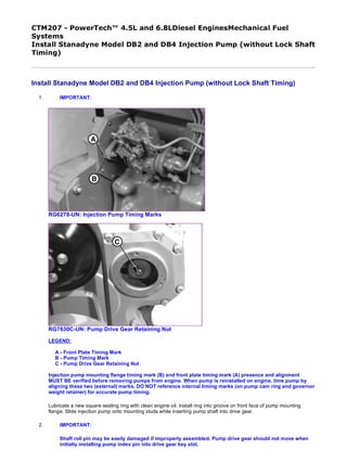
RG6278-UN: Injection Pump Timing Marks
RG7630C-UN: Pump Drive Gear Retaining Nut
LEGEND:
A - Front Plate Timing Mark
B - Pump Timing Mark
C - Pump Drive Gear Retaining Nut
Injection pump mounting flange timing mark (B) and front plate timing mark (A) presence and alignment
MUST BE verified before removing pumps from engine. When pump is reinstalled on engine, time pump by
aligning these two (external) marks. DO NOT reference internal timing marks (on pump cam ring and governor
weight retainer) for accurate pump timing.
Lubricate a new square sealing ring with clean engine oil. Install ring into groove on front face of pump mounting
flange. Slide injection pump onto mounting studs while inserting pump shaft into drive gear.
2. IMPORTANT:
Shaft roll pin may be easily damaged if improperly assembled. Pump drive gear should not move when
initially installing pump index pin into drive gear key slot.
1/4
2019/12/29file:///C:/ProgramData/Service%20ADVISOR/Temp/CTM207_09001faa807b...
2. Check pump shaft and index pin for proper alignment with pump drive gear key slot.
3. Install injection pump partially onto mounting studs without engaging pump pilot hub into engine front plate.
4. IMPORTANT:
DO NOT tighten hex nuts more than three full turns on mounting studs. Pump drive shaft index pin may
be damaged if pin is not properly aligned with drive gear key slot and nuts are tightened more than three
turns.
Install three flat washers, lock washers, and hex nuts onto pump mounting studs. Tighten nuts three turns only so that
pump will not fall off mounting studs.
NOTE:
The pump drive gear should begin to move forward (away from engine front plate) with the pump
when flange is approximately 3.2 mm (1/8 in.) away from engine front plate.
5. Install pump mounting flange flush to engine front plate with drive gear held flush against front side of engine front
plate.
6. IMPORTANT:
DO NOT use tightening force of pump mounting stud nuts to pull pump shaft into drive gear ID.
With the pump shaft index pin properly engaged in the drive gear key slot, finger tighten mounting stud nuts.
7. Push pump drive gear firmly onto shaft taper. Install washer and retaining nut (C) onto end of shaft. Tighten retaining
nut to the following torque specification:
8. IMPORTANT:
To avoid damage to O-ring, Do NOT overtighten cap screws on pump cover plate.
RG9089-UN: 6-Cylinder Engine (Left)
4-Cylinder Engine (Right)
Item Measurement Specification
Stanadyne DB2 Fuel Injection Pump
Drive Gear-to-Shaft Retaining Nut
Torque 125 N˙m (92 lb-ft)
Stanadyne DB4 Fuel Injection Pump
Drive Gear-to-Shaft Retaining Nut
Torque 200 N˙m (148 lb-ft)
2/4
2019/12/29file:///C:/ProgramData/Service%20ADVISOR/Temp/CTM207_09001faa807b...
3. RG5664-UN: Fuel Supply, Return and Pressure Lines
LEGEND:
A - Engine Block Side
B - Outlet Connection to No. 1 Cylinder
C - Fuel Supply Line
D - Fuel Return Line
E - Fuel Delivery (Pressure) Lines (4 or 6 used)
Install access cover plate using a new O-ring, if needed. Apply LOCTITE ® 242 (T43512) to cap screw threads and
tighten to specifications.
9. Align timing mark on pump flange with timing mark on front plate.
10. Tighten three hex nuts securing the pump to the front plate to specifications.
11. Connect injection pump pressure lines (E). Beginning with outlet (B) and continuing around the pump head in
counterclockwise direction, attach lines in same order as engine firing (1-5-3-6-2-4 on 6-cylinder engines and 1-3-4-2
on 4-cylinder engines).
12. Tighten fuel delivery (pressure) lines at pump to specifications, using a suitable 17 mm deep-well socket.
13. IMPORTANT:
ALWAYS use a backup wrench when loosening or tightening fuel delivery lines at fuel injection pump, so
that the pump discharge fittings are not altered. This prevents possible internal pump damage.
Connect fuel supply line (C) and fuel return line (D).
14. Connect fuel shut-off cable and speed control linkage, if equipped. Install and securely tighten electrical connections to
shut-off solenoid and throttle positioning solenoid, if equipped. Connect cold start switch, if equipped.
Item Measurement Specification
Rotary Injection Pump Front Access
Plate Cap Screws
Torque 6 N˙m (4.5 lb-ft) (54 lb-in.)
Item Measurement Specification
Rotary Injection Pump Mounting
Nuts
Torque 27 N˙m (20 lb-ft)
Item Measurement Specification
Fuel Injection Pump Delivery Lines
(At Pump)
Torque 27 N˙m (20 lb-ft)
3/4
2019/12/29file:///C:/ProgramData/Service%20ADVISOR/Temp/CTM207_09001faa807b...
4. 15. Bleed air from fuel system as outlined in this group. (See BLEED THE FUEL SYSTEM in this group.) Start engine, run
for several minutes and check entire fuel system for leaks.
16. If required, proceed with Dynamic Timing.
LOCTITE is a registered trademark of Loctite Corp. OUO1082,0000045-19-20080902
4/4
2019/12/29file:///C:/ProgramData/Service%20ADVISOR/Temp/CTM207_09001faa807b...
5. CTM207 - PowerTech™ 4.5L and 6.8LDiesel EnginesMechanical Fuel Systems
Install Stanadyne Model DB4 Injection Pump (with Lock Shaft Timing)
Install Stanadyne Model DB4 Injection Pump (with Lock Shaft Timing)
1. IMPORTANT:
Repaired or replacement pumps have the drive shaft locked by the manufacturer or by the workshop Dealer once proper pump timing orientation has been established.
To comply with Emission Regulations, do not install pump which has not the drive shaft locked. Bring the pump to a Stanadyne Agent for timing and installation of the
lock shaft timing screw.
NOTE:
When installing pump, do not use previous timing marks (if any) on front plate and on pump flange.
CD31013-UN: Install Sealing Ring
CD31012-UN: Install Injection Pump
LEGEND:
A - Sealing Ring
B - Injection Pump Mounting Studs
C - Sealing Ring Groove
Lubricate a new square sealing ring (A) whit clean engine oil. Install ring into groove (C) on front face of pump mounting flange.
2. Slide and rotate injection pump onto mounting studs (B) while inserting pump shaft into drive gear.
IMPORTANT:
Rotate the complete pump to align pump shaft key with gear key slot.
3.
CD31011-UN: Install Stud Nuts
1/5
2019/12/29file:///C:/ProgramData/Service%20ADVISOR/Temp/CTM207_09001faa80b1...
6. CD31014-UN: Install Drive Gear Washer and Nut
CD31015-UN: Install Injection Pump Drive Gear Cover
LEGEND:
A - Injection Pump Mounting Stud Nuts
B - Drive Gear Washer
C - Drive Gear Retaining Nut
D - Drive Gear Cover
E - Drive Gear Cover O-Ring
Install the 3 injection pump mounting stud nuts (A) but do not tighten at this stage.
4. Install washer (B) and drive gear retaining nut (C) onto end of pump shaft. Tighten to specifications.
5. Rotate pump towards engine to eliminate the gear backlash then tighten to specifications.
6. Install injection pump divre gear cover (D) using a new O-ring (E), if needed. Apply LOCTITE ® 242 (T43512) to cap screw threads and tighten to specifications.
Item Measurement Specification
Stanadyne DB4 Fuel Injection Pump
Drive Gear-to-Shaft Retaining Nut
Torque 200 N˙m (148 lb-ft)
Item Measurement Specification
Injection Pump Mounting Nuts Torque 27 N˙m (20 lb-ft)
Item Measurement Specification
Injection Pump Divre Gear Cover
Cap Screws
Torque 6 N˙m (4.5 lb-ft) (54 lb-in.)
2/5
2019/12/29file:///C:/ProgramData/Service%20ADVISOR/Temp/CTM207_09001faa80b1...
7. 7.
RG15538-UN: Lock Screw in Locked Position
RG15539-UN: Lock Screw in Unlocked Position
3/5
2019/12/29file:///C:/ProgramData/Service%20ADVISOR/Temp/CTM207_09001faa80b1...
8. LEGEND:
A - Lock Screw
B - Key Plate
Loosen injection pump drive shaft lock screw (A) and position key plate (B) to unlocked position (small diameter end behind the lock screw head). Tighten lock screw to specification.
8.
CD31016-UN: High Pressure Outlet for Cylinder N° 1
CD31017-UN: Install High Pressure Fuel Lines
LEGEND:
A - High Pressure Outlet for Cylinder N° 1
B - High Pressure Fuel Lines
C - Suitable 17 mm Socket
D - Backup Wrench
Connect high pressure fuel lines (B). Beginning with outlet (A) and continuing around the pump head in counterclockwise direction, attach lines in same order as engine firing (1-5-3-6-2-4
on 6-cylinder engines and 1-3-4-2 on 4-cylinder engines).
IMPORTANT:
ALWAYS use a backup wrench (D) when loosening or tightening fuel delivery lines at fuel injection pump, so that the pump discharge fittings are not altered. This
prevents possible internal pump damage.
9. Tighten high pressure fuel lines at pump to specifications, using a suitable 17 mm deep-well socket (C).
Item Measurement Specification
Lock Shaft Timing Lock Screw—
Unlocked Position
Torque 8 N˙m (71 lb-in.)
Item Measurement Specification
Fuel Injection Pump Delivery Lines
(At Pump)
Torque 27 N˙m (20 lb-ft)
4/5
2019/12/29file:///C:/ProgramData/Service%20ADVISOR/Temp/CTM207_09001faa80b1...
9. 10.
CD31018-UN: Install Connections
LEGEND:
A - Fuel Supply Line
B - Fuel Return Line
C - Fuel Shut-Off Wires
D - Speed Control Linkage
E - Cold Start Switch
F - High Pressure Fuel Lines
Connect fuel supply line (A) and fuel return line (B).
11. Connect fuel shut-off wires (C) and speed control linkage (D), if equipped.
12. Connect cold start switch (E).
NOTE:
Fuel injection pumps with lock shaft timing do not require additional static or dynamic timing.
13. Bleed air from fuel system as outlined in this group. (See BLEED THE FUEL SYSTEM in this group.) Start engine, run for several minutes and check entire fuel system for leaks.
LOCTITE is a registered trademark of Loctite Corp. CD03523,00001C1-19-20090528
5/5
2019/12/29file:///C:/ProgramData/Service%20ADVISOR/Temp/CTM207_09001faa80b1...
10. CTM207 - PowerTech™ 4.5L and 6.8LDiesel EnginesMechanical Fuel
Systems
Remove Delphi/Lucas Fuel Injection Pump
Remove Delphi/Lucas Fuel Injection Pump
RG7722-UN: Delphi/Lucas Fuel Injection Pump
RG9069-UN: Fuel Supply, Return and Pressure Lines
LEGEND:
A - Fuel Return Line
B - Fuel Delivery (Pressure) Lines
C - Fuel Supply Line
D - Aneroid Line
NOTE:
The injection pump serial number tag (bold arrow) is located on the bottom of the pump.
1. IMPORTANT:
Never steam clean or pour cold water on a fuel injection pump while the pump is running or while it is
warm. Doing so may cause seizure of internal rotating pump parts.
Clean the fuel injection pump, lines and area around the pump with cleaning solvent or a steam cleaner.
2. Disconnect shut-off cable and speed control linkage, if equipped. Disconnect electrical connection to shut-off
1/4
2019/12/29file:///C:/ProgramData/Service%20ADVISOR/Temp/CTM207_09001faa8018...
11. solenoid or throttle positioning solenoid, if equipped. Disconnect cold start switch, if equipped. Tag electrical wires
for correct reassembly.
3. IMPORTANT:
ALWAYS use a backup wrench when loosening or tightening fuel lines at injection pump so that
discharge fittings are not altered to prevent possible internal pump damage.
Disconnect fuel return line (A), fuel supply line (C) and aneroid line (D).
4. Disconnect all fuel delivery (pressure) lines (B) from injection pump using a suitable 17 mm deep-well crowsfoot
socket.
5.
RG7629A-UN: Injection Pump Drive Cover
RG7630B-UN: Pump Drive Gear Retaining Nut
LEGEND:
A - Drive Gear Cover
B - Drive Gear Retaining Nut
Remove injection pump drive gear cover (A). Remove drive gear retaining nut (B) and washer from end of pump
shaft. Be careful not to let washer fall inside timing gear cover.
6. NOTE:
The injection pump drive gear fits snugly onto a tapered drive shaft and is indexed by a
Woodruff key installed in drive shaft. Use JDG1560 Drive Gear Puller (A) to remove drive gear
2/4
2019/12/29file:///C:/ProgramData/Service%20ADVISOR/Temp/CTM207_09001faa8018...
12. Thank you very much for
your reading. Please Click
Here. Then Get COMPLETE
MANUAL. NO WAITING
NOTE:
If there is no response to
click on the link above,
please download the PDF
document first and then
click on it.
13. from shaft.
RG7631-UN: Pump Drive Gear Puller in Place
LEGEND:
A - Drive Gear Puller
B - Forcing Screw
C - Cap Screws
Attach JDG1560 Injection Pump Drive Gear Puller to injection pump drive gear as shown. Follow instructions
provided with tool set.
7. NOTE:
Replace 6 mm, Grade 12.9 cap screws (C) as needed.
Evenly tighten the two 6 mm, Grade 12.9 screws (threaded in drive gear) and snugly tighten center forcing screw
(B) against end of pump shaft.
8. Tighten center forcing screw until pump drive gear is free from tapered shaft. Remove JDG1560 Injection Pump
Drive Gear Puller from drive gear.
9.
RG7723A-UN: Injection Pump Timing Marks
LEGEND:
A - Timing Mark on Front Plate
B - Timing Mark on Injection Pump Flange
Check to make sure that timing marks on back side of front plate (A) and injection pump flange (B) are present and
3/4
2019/12/29file:///C:/ProgramData/Service%20ADVISOR/Temp/CTM207_09001faa8018...
14. properly aligned. This ensures that repaired or replacement pump can be properly timed to engine when installed.
If timing mark is not clearly visible on front plate, scribe a visible reference mark as accurately as possible in-line
with mark on pump flange.
10. Remove injection pump mounting stud nuts. Remove injection pump from mounting studs.
RG,35,JW7605-19-20020708
4/4
2019/12/29file:///C:/ProgramData/Service%20ADVISOR/Temp/CTM207_09001faa8018...
15. CTM207 - PowerTech™ 4.5L and 6.8LDiesel EnginesMechanical Fuel
Systems
Repair Delphi/Lucas Fuel Injection Pump
Repair Delphi/Lucas Fuel Injection Pump
IMPORTANT:
DO NOT disassemble the Delphi/Lucas fuel injection pump any further than necessary for installing available
repair parts, not even for cleaning.
Have an authorized ADS Diesel Repair Station perform all injection pump testing, adjustments, and repairs.
RG,35,JW7604-19-20020708
1/1
2019/12/29file:///C:/ProgramData/Service%20ADVISOR/Temp/CTM207_09001faa8018...