John deere power tech 10.5l diesel base engine service repair technical manual (ctm100)
1. CTM100 - 10.5 L and 12.5 L Diesel Engines Base Engine
Remove and Install Rocker Arm Cover
Remove and Install Rocker Arm Cover
Remove Rocker Arm Cover
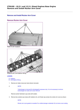
RG8173-UN: Isolators
RG8818-UN: Unit Injector Wiring
LEGEND:
A - Isolators
B - Unit Injector Wiring
1. Remove air intake cross-over tube (shown removed).
2. NOTE:
Turbocharger is removed for photographic purposes only. It is not necessary to remove
turbocharger for rocker arm cover removal.
Remove center hold-down cap screw with isolator.
3. Remove two outside cap screws with isolators (A), and thread cap screws into rocker arm cover as shown.
NOTE:
Rocker arm cover gasket is reusable if no visible damage is detected. Do not store cover resting
1/2
2019/12/18file:///C:/ProgramData/Service%20ADVISOR/Temp/CTM100_09001faa800f...
2. on gasket surface.
4. Lift rocker arm cover off engine.
Install Rocker Arm Cover IMPORTANT:
Always check routing of unit injector wiring (B) before installing rocker arm cover. Wiring should be positioned
so that rocker arms never contact wire.
1. Inspect rocker arm cover gasket to ensure that gasket is properly seated in groove and that contact face is clean.
2. Position rocker arm cover onto two locating dowels in cylinder head.
3. Install center hold-down cap screw with isolator. Tighten to specifications.
4. Install two outside hold-down cap screws with isolators. Tighten to specifications.
5. Install air intake cross-over tube and tighten connections securely.
Item Measurement Specification
[Rocker Arm Cover Hold-Down Cap
ScrewsTighten center cap screw
first, then tighten sides.]
Torque 30 N˙m (22 lb-ft)
Item Measurement Specification
[Rocker Arm Cover Hold-Down Cap
ScrewsTighten center cap screw
first, then tighten sides.]
Torque 30 N˙m (22 lb-ft)
RG,RG34710,60-19-20051213
2/2
2019/12/18file:///C:/ProgramData/Service%20ADVISOR/Temp/CTM100_09001faa800f...
3. CTM100 - 10.5 L and 12.5 L Diesel Engines Base Engine
Clean and Inspect Crankcase Ventilation Assembly
Clean and Inspect Crankcase Ventilation Assembly
RG10242-UN: Crankcase Ventilation Assembly
LEGEND:
A - O-Rings
B - Ventilator Assembly
1. Remove ventilation outlet tube from rocker arm cover (shown removed).
2. NOTE:
Ventilator assembly-to-rocker cover self-tapping cap screws have been replaced by flange head
cap screws with pre-applied sealant. Discard old self-tapping cap screws and replace with new
cap screws.
Remove two cap screws securing ventilator assembly (B) to cover and remove.
3. Clean ventilator assembly in solvent and dry with compressed air.
4. Install ventilator assembly in reverse order of removal. Replace O-rings (A) as necessary.
5. Tighten ventilator assembly-to-rocker arm cover cap screws to specifications.
6. Install ventilator outlet tube onto elbow attached to rocker arm cover.
Item Measurement Specification
Crankcase Vent Baffle-to-Rocker
Arm Cover Cap Screws
Torque 15 N˙m (11 lb-ft) (133 lb-in.)
RG,RG34710,61-19-20020903
1/1
2019/12/18file:///C:/ProgramData/Service%20ADVISOR/Temp/CTM100_09001faa800f...
4. CTM100 - 10.5 L and 12.5 L Diesel Engines Base Engine
Replace Rocker Arm Cover Gasket
Replace Rocker Arm Cover Gasket
RG8784-UN: Replacing Rocker Arm Cover Gasket
LEGEND:
A - Gasket Double Lips
1. Remove rocker arm cover. (See REMOVE AND INSTALL ROCKER ARM COVER earlier in this group.)
2. Remove existing gasket from cover and discard. Clean gasket groove as needed.
3. Position new gasket at two front corners of cover with double lips (A) of gasket facing up.
4. IMPORTANT:
1/2
2019/12/18file:///C:/ProgramData/Service%20ADVISOR/Temp/CTM100_09001faa800f...
5. DO NOT stretch gasket while seating in groove of cover.
Seat gasket on front side of cover and proceed around entire cover gasket groove using a deep-well socket.
5. Re-seat gasket again (especially in corners) after entire gasket is installed in groove.
RG,RG34710,62-19-19970930
2/2
2019/12/18file:///C:/ProgramData/Service%20ADVISOR/Temp/CTM100_09001faa800f...
6. CTM100 - 10.5 L and 12.5 L Diesel Engines Base Engine
Check and Adjust Valve Assembly Clearances and Injector Preload
Check and Adjust Valve Assembly Clearances and Injector Preload
RG8228A-UN: JDG971 Timing Pin in Camshaft
RG8227D-UN: JDG971 Timing Pin in Crankshaft
RG11165-UN: Camshaft Timing Slot
LEGEND:
A - JDG971 Timing Pin
B - JDG820 Flywheel Turning Tool
C - JDG971 Timing Pin
D - Single Timing Slot
E - Double Timing Slot
Rocker arm assembly adjustments consist of intake and exhaust valve clearance (lash) and electronic unit injector preload adjustment.
1/5
2019/12/18file:///C:/ProgramData/Service%20ADVISOR/Temp/CTM100_09001faa80bf...
7. CAUTION:
To prevent accidental starting of engine while performing rocker arm adjustment, ALWAYS disconnect NEGATIVE (–) battery terminal.
IMPORTANT:
All rocker arm assembly adjustments MUST BE performed with engine COLD.
1. Remove rocker arm cover. (See REMOVE AND INSTALL ROCKER ARM COVER earlier in this group.)
2. Remove plug from cylinder block and install JDG820 Flywheel Turning Tool (B).
3. Remove threaded plug from timing hole below oil cooler and filter housing assembly.
4. IMPORTANT:
Timing pin MUST BE installed in slot of camshaft first, then install second timing pin in crankshaft slot by carefully rocking flywheel back and
forth.
Rotate engine flywheel in running direction (counterclockwise as viewed from rear) until JDG971 Timing Pin (A) engages single timing slot (D) in camshaft. The
proper timing slot can be found by viewing camshaft timing lobe through camshaft timing pin bore while rotating engine. The double timing slot (E) will be at
approximately 11 o'clock (viewed from rear of engine) when pin is installed in slot (D).This ensures that engine is locked at TDC of No. 1 cylinder's compression
stroke. Intake and exhaust rocker arms on No. 1 cylinder should be loose.
5. IMPORTANT:
DO NOT insert timing pin full depth into cylinder block crankshaft timing hole when rotating engine flywheel until double slot on camshaft
timing lobe is at approximately 11 o'clock (viewed from rear of engine) to avoid crankshaft counterweight bending timing pin.
Slightly move engine flywheel back and forth with turning tool until a second JDG971 Timing Pin (C) can be installed in slot in crankshaft. This ensures that
camshaft and crankshaft are in sync (properly timed).
If timing pin does not enter crankshaft timing slot, crankshaft is not properly timed with camshaft. Crankshaft MUST BE timed to camshaft. (See CHECK AND
ADJUST CAMSHAFT-TO-CRANKSHAFT TIMING in Group 050.)
6.
RG8773-UN: Rocker Arm Assembly Identification
RG8232-UN: Adjusting Valve Lash/Clearance
LEGEND:
B - Valve Stem Tip
2/5
2019/12/18file:///C:/ProgramData/Service%20ADVISOR/Temp/CTM100_09001faa80bf...
8. Check and adjust (as needed) valve stem-to-bridge clearance (lash) on intake valves Nos. 1, 2, and 4, and exhaust valves Nos. 1, 3, and 5 (shaded locations).
Adjust preload on electronic unit injectors Nos. 3, 5, and 6 (shaded locations).
Valve clearance is adjusted using JDG1333 Feeler Gauge Set or equivalent 1/4 inch (6.0 mm) wide automotive ignition point-type feeler gauge installed at the
joint between the valve bridge and valve stem tip (B) that is near the exhaust (right) side of engine.Loosen lock nuts, set clearance with adjusting screw and
tighten lock nut to specified torque while holding adjusting screw stationary.
7. Tighten intake and exhaust valve adjusting screw lock nuts to specifications.
8. Set electronic unit injector preload by turning the EUI rocker arm adjusting screw in until there is zero clearance between the rocker arm roller and camshaft
lobe. Next, turn the adjusting screw in an additional 1/2 turn (180°). Hold adjusting screw stationary while tightening lock nut to specified torque. Tighten EUI
adjusting screw lock nuts to specifications.
9.
RG8774-UN: Rocker Arm Assembly Identification
RG8229-UN: Locking Engine at No.6 TDC
LEGEND:
A - Flywheel Reference Mark
B - Timing Pin
Reference mark flywheel (A) as shown with engine locked at No.1 TDC compression stroke.
10. IMPORTANT:
DO NOT insert timing pin full depth into cylinder block when rotating engine flywheel until reference mark is within a few degrees of a full
crankshaft revolution to eliminate possibility of crankshaft counterweight bending timing pin.
Item Measurement Specification
Valve Stem-to-Bridge Clearance (Engine Cold)
Intake Valve Clearance 0.58 ± 0.05 mm (0.023 ± 0.002 in.)
Exhaust Valve Clearance 1.08 ± 0.05 mm (0.043 ± 0.002 in.)
Item Measurement Specification
Intake and Exhaust Valve Adjusting
Screw Lock Nuts
Torque 50 N˙m (37 lb-ft)
Item Measurement Specification
Electronic Unit Injector Preload 0.00 mm (in.) clearance plus
additional 1/2 turn (stroke injector
plunger travel to 1.125 mm)
Electronic Unit Injector Adjusting
Screw Lock Nuts
Torque 65 N˙m (48 lb-ft)
3/5
2019/12/18file:///C:/ProgramData/Service%20ADVISOR/Temp/CTM100_09001faa80bf...
9. Remove both timing pins and rotate engine flywheel one full revolution (360°) until timing pin (B) enters slot in crankshaft again. Engine will now be locked at
No. 6 TDC compression stroke.
11. Check and adjust, as needed, valve clearance (lash) on intake valves Nos. 3, 5, and 6 and exhaust valves Nos. 2, 4, and 6 (shaded locations). Adjust preload
on injectors Nos. 1, 2, and 4 (shaded locations).
12. Tighten intake and exhaust valve adjusting screw lock nuts to specifications.
Tighten EUI adjusting screw lock nuts to specifications.
13. IMPORTANT:
Thoroughly inspect ALL intake and exhaust valve bridges (A) for proper seating on valve stems (B) from both sides of engine. Also, be sure that
push tubes (C) are properly seated in top of valve bridge.
Use a flashlight and carefully check each bridge (for proper seating on valve stems) from both sides of the engine, by lifting up on each bridge
to verify proper seating. VALVE BRIDGES THAT ARE NOT PROPERLY SEATED ON VALVE STEMS WILL RESULT IN MAJOR ENGINE VALVE
TRAIN FAILURE.
RG9743-UN: Inspect Valves
RG9626A-UN: Adjusting Screws
LEGEND:
A - Valve Bridges
B - Valve Stems
C - Push Tubes
D - Adjusting Screws
Item Measurement Specification
Intake and Exhaust Valve Adjusting
Screw Lock Nuts
Torque 50 N˙m (37 lb-ft)
Item Measurement Specification
Electronic Unit Injector Adjusting
Screw Lock Nuts
Torque 65 N˙m (48 lb-ft)
4/5
2019/12/18file:///C:/ProgramData/Service%20ADVISOR/Temp/CTM100_09001faa80bf...
10. Check that all intake rocker arm adjusting screws (D) have approximately the same number of threads visible above lock nut. Normally flush to maximum of two
threads.
If the number of threads above lock nut at any location is visually different, verify bridge seating and readjust valve clearance to ensure everything is within
specification at this location.
14. Install plug in timing pin hole below oil cooler and tighten to specifications.
Item Measurement Specification
Timing Pin Plug (Below Oil Cooler) Torque 33 N˙m (24 lb-ft)
AS58880,00000A8-19-20100915
5/5
2019/12/18file:///C:/ProgramData/Service%20ADVISOR/Temp/CTM100_09001faa80bf...
11. CTM100 - 10.5 L and 12.5 L Diesel Engines Base Engine
Remove Rocker Arm Assembly
Remove Rocker Arm Assembly
RG8262B-UN: Removing Valve Bridge and Push Tubes
RG8459A-UN: Removing Rocker Arm Assembly with JDG970A
LEGEND:
A - Rocker Arm Shaft Oil Tubes (Dual Rail Fuel System Only)
B - Rocker Arm Lifting Fixture
C - Push Tubes
D - Valve Bridges
CAUTION:
After operating engine, allow exhaust system to cool before servicing engine.
1. Remove rocker arm cover.
2. Lock camshaft and crankshaft at TDC of No.1 cylinder's compression stroke.
1/2
2019/12/18file:///C:/ProgramData/Service%20ADVISOR/Temp/CTM100_09001faa800f...
12. 3. Remove electronic unit injector wiring harness from rocker arm shaft clamps.
4. IMPORTANT:
ALWAYS loosen all intake, exhaust and EUI rocker arm adjusting screws before removal or
installation of rocker arm assembly to relieve pressure. This allows for a more uniform rocker arm cap
screw clamp load and reduces the possibility of damage to valve train components.
Remove push tubes and valve bridges immediately after relieving rocker arm pressure. Push tubes
can fall into oil drain opening of cylinder head causing oil pan removal to retrieve tubes.
Loosen EUI, intake, and exhaust valve rocker arm adjusting screw lock nut and relieve pressure at all locations.
5. Remove push tubes (C) and valve bridges (D) from all valve stems.
6. Remove two rocker arm shaft oil tubes (A) (dual rail system only). Remove rocker arm shaft hold-down clamps.
IMPORTANT:
Rocker arm shaft hold-down clamp cap screws can not be reused. Use new cap screws for
reassembly.
7. Install shaft clamp cap screw in end hole of each rocker arm shaft so that rocker arms do not slide off shaft when
lifted.
CAUTION:
A second set of pins has been added to JDG970A tool. With 6125 Tier II engines (engine
serial no. 030000—), the holes for the pins in the rocker arm shaft are smaller. The new pins
have a smaller diameter shaft and are marked “JDG1847”. To safely handle the rocker arm
shaft assembly, BE CERTAIN to verify the engine serial number, then use the correct pins
for that engine.
8. Depress actuator (ball) pins and install JDG970A Rocker Arm Lifting Fixture (B) into rocker arm shaft cap screw
holes as shown.Replace pins to seat ball locks.
9. Remove both front and rear rocker arm and shaft assemblies using JDG970A Rocker Arm Lifting Fixture.
10. Discard rocker arm shaft hold-down clamp cap screws.
RG,RG34710,64-19-20001221
2/2
2019/12/18file:///C:/ProgramData/Service%20ADVISOR/Temp/CTM100_09001faa800f...
13. CTM100 - 10.5 L and 12.5 L Diesel Engines Base Engine
Remove Cylinder Head
Remove Cylinder Head
RG8187A-UN: Removing Turbocharger and Exhaust Manifold
LEGEND:
A - Turbocharger
B - Exhaust Manifold
C - Thermostat Housing/Water Manifold
On some applications, it may be necessary to remove engine from machine to service cylinder head. Refer to your Machine
Technical Manual for engine removal procedure.
CAUTION:
After operating engine, allow exhaust system to cool before servicing engine.
DO NOT drain coolant until the coolant is below operating temperature. Only remove radiator filler
cap when cool enough to touch with bare hands. Slowly loosen cap to first stop to relieve pressure
before removing completely.
1. Drain all oil and coolant.
2. Remove intake manifold (6105H and 6125H engines). (See REMOVE, INSPECT AND INSTALL INTAKE
MANIFOLD in Group 080.)
3. Remove turbocharger (A). (See REMOVE TURBOCHARGER in Group 080.)
4. Remove exhaust manifold (B). (See REMOVE, INSPECT AND INSTALL EXHAUST MANIFOLD in Group 080.)
5. On 6105A and 6125A engines, remove aftercooler assembly. (See REMOVE AND INSTALL AFTERCOOLER
ASSEMBLY in Group 080.)
6. Remove thermostat housing/water manifold (C). (See REMOVE AND INSTALL THERMOSTAT HOUSING in Group
070.)
7. Remove rocker arm assembly. (See REMOVE AND INSTALL ROCKER ARM ASSEMBLY , earlier in this group).
1/4
2019/12/18file:///C:/ProgramData/Service%20ADVISOR/Temp/CTM100_09001faa800f...
14. Thank you very much for
your reading. Please Click
Here. Then Get COMPLETE
MANUAL. NO WAITING
NOTE:
If there is no response to
click on the link above,
please download the PDF
document first and then
click on it.
15. 8. Remove electronic unit injectors and wiring harness. Refer to the appropriate fuel system repair manual.
Delphi/Lucas ECU controlled fuel systems:
See REMOVE AND INSTALL ELECTRONIC UNIT INJECTORS in CTM115, Section 02, Group 090.
John Deere Level 6 ECU controlled fuel systems:
See REMOVE AND INSTALL ELECTRONIC UNIT INJECTORS in CTM188, Section 02, Group 090 (dual
rail fuel systems).
See REMOVE AND INSTALL ELECTRONIC UNIT INJECTORS in CTM188, Section 02, Group 091 (single
rail fuel systems).
9. Remove fan drive hub and camshaft gear access cover.
10.
RG8251A-UN: Removing Camshaft Gear
RG8264B-UN: Removing Supply Pump and Fuel Manifold (Early Engine Shown)
2/4
2019/12/18file:///C:/ProgramData/Service%20ADVISOR/Temp/CTM100_09001faa800f...
16. RG8544B-UN: DFRG4 Camshaft Locking Tool
LEGEND:
A - Gear Retaining Washer
B - Camshaft Gear
C - Fuel Manifold
D - Fuel Supply Pump
E - DFRG4 Camshaft Locking Tool
Remove six cap screws securing camshaft gear retaining washer (A) and remove camshaft gear (B).
11. NOTE:
Later engines: 10.5 L S.N. (003764— ) and 12.5 L S.N. (010967— ) with single rail fuel systems
do not have a fuel manifold. Return fuel line is connected to port of single rail in back of cylinder
head. Inlet line and port are on left side of head up by No.1 cylinder.
Remove fuel manifold block (C) on engines with dual rail systems, or disconnect fuel inlet and return lines on single
rail systems. Refer to the appropriate fuel system repair manual.
Delphi/Lucas ECU controlled fuel systems:
See REMOVE AND INSTALL FUEL MANIFOLD in CTM115, Section 02, Group 090.
John Deere Level 6 ECU controlled fuel systems:
See REMOVE AND INSTALL FUEL MANIFOLD in CTM188, Section 02, Group 090.
12. Remove fuel supply pump. Refer to the appropriate fuel system repair manual.
Delphi/Lucas ECU controlled fuel systems:
See REMOVE AND INSTALL FUEL SUPPLY PUMP in CTM115, Section 02, Group 090.
John Deere Level 6 ECU controlled fuel systems:
See REMOVE AND INSTALL FUEL SUPPLY PUMP in CTM188, Section 02, Group 090 (dual rail fuel
systems).
See REMOVE AND INSTALL FUEL SUPPLY PUMP in CTM188, Section 02, Group 091 (single rail fuel
systems).
13. NOTE:
Cylinder head can be removed without removing camshaft.
IMPORTANT:
If cylinder head is removed with camshaft installed, secure camshaft in bushings with DFRG4
3/4
2019/12/18file:///C:/ProgramData/Service%20ADVISOR/Temp/CTM100_09001faa800f...
17. Camshaft Locking Tool (E) so that camshaft journals and bushings are not damaged by camshaft
sliding out of bushings. (See DFRG4-CAMSHAFT LOCKING TOOL in Section 05, Group 190 for details
on this dealer fabricated tool.)
Camshaft position sensor MUST BE removed from air intake side of cylinder head when removing or
installing camshaft to prevent camshaft binding on sensor.
Remove camshaft front thrust ring. Remove camshaft position sensor and remove camshaft if desired (see
REMOVE AND INSTALL CAMSHAFT in Group 050).
14. NOTE:
If removing head with camshaft installed, camshaft will have to be rotated to remove two of the
cylinder head cap screws.
RG8285-UN: Removing Cylinder Head
Remove 26 cylinder head cap screws with washers and discard.
15. IMPORTANT:
DO NOT use screwdrivers or prybars between cylinder block and head to loosen gasket seal.
Screwdrivers and prybars can damage head and block gasket surfaces.
Carefully lift cylinder head from block using an overhead hoist or floor crane. Place head on a clean, flat surface.
16. Remove cylinder head gasket. Inspect gasket for any manufacturing imperfections. Inspect head, gasket, and check
for possible oil, coolant, or combustion chamber leakage.
NOTE:
DO NOT rotate engine crankshaft with cylinder head removed unless all cylinder liners are
secured with cap screws and large, flat washers. (See REMOVE PISTONS AND
CONNECTING RODS in Group 030.)
RG,RG34710,65-19-19990813
4/4
2019/12/18file:///C:/ProgramData/Service%20ADVISOR/Temp/CTM100_09001faa800f...
![on gasket surface.
4. Lift rocker arm cover off engine.
Install Rocker Arm Cover IMPORTANT:
Always check routing of unit injector wiring (B) before installing rocker arm cover. Wiring should be positioned
so that rocker arms never contact wire.
1. Inspect rocker arm cover gasket to ensure that gasket is properly seated in groove and that contact face is clean.
2. Position rocker arm cover onto two locating dowels in cylinder head.
3. Install center hold-down cap screw with isolator. Tighten to specifications.
4. Install two outside hold-down cap screws with isolators. Tighten to specifications.
5. Install air intake cross-over tube and tighten connections securely.
Item Measurement Specification
[Rocker Arm Cover Hold-Down Cap
ScrewsTighten center cap screw
first, then tighten sides.]
Torque 30 N˙m (22 lb-ft)
Item Measurement Specification
[Rocker Arm Cover Hold-Down Cap
ScrewsTighten center cap screw
first, then tighten sides.]
Torque 30 N˙m (22 lb-ft)
RG,RG34710,60-19-20051213
2/2
2019/12/18file:///C:/ProgramData/Service%20ADVISOR/Temp/CTM100_09001faa800f...](data:image/gif;base64,R0lGODlhAQABAIAAAAAAAP///yH5BAEAAAAALAAAAAABAAEAAAIBRAA7)