
Recommended
Recommended
More Related Content
More from fujskekskemm
More from fujskekskemm (20)
Recently uploaded
Recently uploaded (20)
John deere 107 h riding lawn tractor service repair technical manual (tm113419)
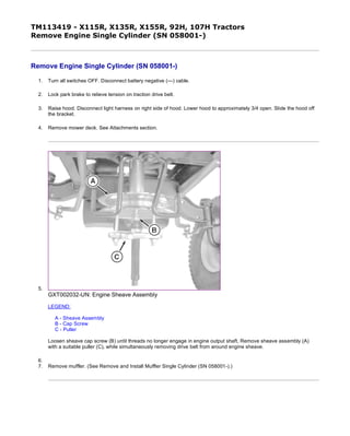
- 1. TM113419 - X115R, X135R, X155R, 92H, 107H Tractors Remove Engine Single Cylinder (SN 058001-) Remove Engine Single Cylinder (SN 058001-) 1. Turn all switches OFF. Disconnect battery negative (—) cable. 2. Lock park brake to relieve tension on traction drive belt. 3. Raise hood. Disconnect light harness on right side of hood. Lower hood to approximately 3/4 open. Slide the hood off the bracket. 4. Remove mower deck. See Attachments section. 5. GXT002032-UN: Engine Sheave Assembly LEGEND: A - Sheave Assembly B - Cap Screw C - Puller Loosen sheave cap screw (B) until threads no longer engage in engine output shaft, Remove sheave assembly (A) with a suitable puller (C), while simultaneously removing drive belt from around engine sheave. 6. 7. Remove muffler. (See Remove and Install Muffler Single Cylinder (SN 058001-).) 页码,1/4(W)w 11/26/2019file://C:ProgramDataService ADVISORTempTM113419_09001faa82f5b559.html
- 2. 8. GXT002024-UN: Engine and Main Wiring Harness Connectors LEGEND: D - Harness Connectors E - Stator Wire Disconnect engine wiring harness connectors from main wiring harness (D). 9. Disconnect stator wire (E). 10. CAUTION: Avoid Injury! Gasoline is flammable. Do not smoke. Always work in a ventilated area away from open flame or spark producing equipment; including equipment that utilizes pilot lights. 页码,2/4(W)w 11/26/2019file://C:ProgramDataService ADVISORTempTM113419_09001faa82f5b559.html
- 3. GXT002025-UN: Throttle Cable and Fuel Hoses LEGEND: F - Throttle Cable Clamp G - Throttle Cable H - Hose Clamp I - Main Fuel Hose Loosen clamp (F) and remove throttle cable (G). 11. Remove hose clamp (H) and remove fuel hose (I). 12. GXT002026-UN: Engine Mounting Bolts 页码,3/4(W)w 11/26/2019file://C:ProgramDataService ADVISORTempTM113419_09001faa82f5b559.html
- 4. LEGEND: J - Engine Mounting Cap Screws Remove the four engine mounting cap screws (J) securing engine to frame. 13. Remove engine from machine. MX52301,0000D3A-19-20151112 页码,4/4(W)w 11/26/2019file://C:ProgramDataService ADVISORTempTM113419_09001faa82f5b559.html
- 5. TM113419 - X115R, X135R, X155R, 92H, 107H Tractors Install Engine Single Cylinder (SN 058001-) Install Engine Single Cylinder (SN 058001-) 1. CAUTION: Avoid Injury! Gasoline is flammable. Do not smoke. Always work in a ventilated area away from open flame or spark producing equipment; including equipment that utilizes pilot lights. GXT002028-UN: Engine Mounting Cap Screws LEGEND: A - Engine Mounting Cap Screws Place engine onto machine frame and install four engine mounting cap screws (A). 2. Tighten engine mounting bolts to specification. Item Measurement Specification Engine Mounting Bolts Torque 50 N·m (37 lb.-ft.) 页码,1/4(W)w 11/26/2019file://C:ProgramDataService ADVISORTempTM113419_09001faa82f5b6e9.html
- 6. 3. GXT002029-UN: Throttle Cable LEGEND: B - Main Fuel Hose C - Hose Clamp D - Throttle Cable E - Clamp Install fuel hose (B) onto fuel pump and secure with hose clamp (C). 4. Install throttle cable (D) and tighten clamp (E). 5. GXT002030-UN: Engine Electrical 页码,2/4(W)w 11/26/2019file://C:ProgramDataService ADVISORTempTM113419_09001faa82f5b6e9.html
- 7. LEGEND: F - Starter terminal G - Engine Connectors Connect wires to starter terminals (F). 6. Connect main wiring harness connectors (G) to engine connectors. 7. GXT002033-UN: Sheave Installation LEGEND: H - Sheave Assembly I - Cap Screw J - Drive Belt Install sheave assembly (H) and drive belt (J). 8. Secure sheave assembly with cap screw (I) and tighten to specification. 9. Install muffler. (See Remove and Install Muffler Single Cylinder (SN 058001-).) 10. Connect battery. 11. Install hood. (See Install Hood .) 12. Install mower deck. See Attachments section. Item Measurement Specification Sheave Assembly Cap Screw Torque 75 N·m (55 lb.-ft.) 页码,3/4(W)w 11/26/2019file://C:ProgramDataService ADVISORTempTM113419_09001faa82f5b6e9.html
- 8. TM113419 - X115R, X135R, X155R, 92H, 107H Tractors Remove and Install Muffler Single Cylinder (SN 058001-) Remove and Install Muffler Single Cylinder (SN 058001-) Muffler Removal 1. Remove hood. (See Remove Hood ) 2. GXT002023-UN: Muffler Shield LEGEND: A - Pivot Bracket Cap Screws B - Muffler Shield Cap Screws C - Pivot Bracket D - Muffler Shield E - Muffler Flange Screws F - Muffler Support Screw G - Muffler Remove four cap screws (A) securing hood pivot bracket (C) to machine. Remove bracket. 3. Remove four cap screws (B) securing muffler shield (D) to machine. Remove shield. 4. Remove the two muffler flange screws (E) securing the muffler (G) to the engine. 5. Remove muffler support screw (F), gasket, and muffler (G).. Muffler Installation 页码,1/2(W)w 11/26/2019file://C:ProgramDataService ADVISORTempTM113419_09001faa82f5b6ea.html
- 9. 1. Clean gasket mating surfaces of old gasket material. 2. Install new gasket. 3. Install muffler (G) onto engine with muffler flange (E) and support (F) screws. 4. Tighten to specification. 5. Install muffler shield (D) to machine using four cap screws (B). 6. Install hood pivot bracket (C) using four cap screws (A). 7. Install hood. (See Install Hood ) Item Measurement Specification Muffler Screws Torque 16 N·m (140 lb.-in.) MX52301,0000D3C-19-20151112 页码,2/2(W)w 11/26/2019file://C:ProgramDataService ADVISORTempTM113419_09001faa82f5b6ea.html
- 10. TM113419 - X115R, X135R, X155R, 92H, 107H Tractors Remove Cylinder Head Single Cylinder Remove Cylinder Head Single Cylinder MXT003030-UN: Valve Cover Cap Screws LEGEND: A - Cap Screws 1. Disconnect spark plug lead and remove spark plug. 2. Remove air cleaner assembly, carburetor and blower housing. 3. Remove intake manifold and governor control bracket and linkage. 4. Remove valve cover cap screws (A). 5. NOTE: Mark the push rods for reassembly in their original position. The exhaust valve push rod is steel and is marked with a red stripe. The intake valve push rod is aluminum. MXT003031-UN: Rocker Arms and Push Rods LEGEND: B - Adjustment Nuts C - Rocker Arms D - Pivots E - Push Rods Remove rocker arm adjustment nuts (B), rocker arms (C), rocker arm pivots (D), and push rods (E). 页码,1/3(W)w 11/26/2019file://C:ProgramDataService ADVISORTempTM113419_09001faa829c81b4.html
- 11. 6. MXT016301-UN: Cylinder Head Bolts Remove cylinder head bolts in sequence shown. 页码,2/3(W)w 11/26/2019file://C:ProgramDataService ADVISORTempTM113419_09001faa829c81b4.html
- 12. Thank you very much for your reading. Please Click Here. Then Get COMPLETE MANUAL. NO WAITING NOTE: If there is no response to click on the link above, please download the PDF document first and then click on it.
- 13. 7. MXT003033-UN: Cylinder Head and Gasket Remove cylinder head, cylinder head gasket and push rods. Discard the gasket. OUO2003,0000094-19-20151130 页码,3/3(W)w 11/26/2019file://C:ProgramDataService ADVISORTempTM113419_09001faa829c81b4.html
- 14. TM113419 - X115R, X135R, X155R, 92H, 107H Tractors Install Cylinder Head Single Cylinder Install Cylinder Head Single Cylinder MXT003034-UN: Cylinder Head and Gasket LEGEND: A - Alignment Sleeves 1. Clean gasket surfaces. 2. IMPORTANT: Do not use sealer of any kind on gaskets. Place new gasket and cylinder head on cylinder. Align head with alignment sleeves (A) located in the cylinder. 3. Apply thin coat of clean engine oil to threads. Install eight cylinder heads bolts. 4. IMPORTANT: Do not tighten each bolt to final torque in a single step. Incorrect tightening may cause a warped cylinder head. Step-tighten all bolts to 1/3 of the final torque value, then 2/3 of the final torque value. 页码,1/3(W)w 11/26/2019file://C:ProgramDataService ADVISORTempTM113419_09001faa829c81b5.html
- 15. MXT016301-UN: Cylinder Head Bolts Tighten all bolts down evenly by hand. Tighten cylinder head bolts in sequence shown in three even increments to specification. 5. IMPORTANT: The exhaust valve push rod is steel and is marked with a red stripe. The intake valve push rod is aluminum. Item Measurement Specification Cylinder Head Bolts Torque 28.2 N·m (250 lb·in) 页码,2/3(W)w 11/26/2019file://C:ProgramDataService ADVISORTempTM113419_09001faa829c81b5.html
- 16. MXT003036-UN: Rocker Arms and Push Rods LEGEND: B - Nuts C - Rocker Arms D - Pivots E - Push Rods Install push rods (E), rocker arm pivots (D), rocker arms (C), and arm support nuts (B). Tighten to specification. 6. Adjust valve clearance. (See Valve Clearance Adjustment Single Cylinder .) 7. GXT001593-UN: Valve Cover Torque Sequence Install valve cover with new gasket. Tighten to specification using the sequence shown. 8. Install intake manifold. Tighten bolts to specification. 9. Install blower housing. 10. Install governor control bracket and linkage. 11. Install carburetor and adjust governor linkage. (See Install Carburetor Single Cylinder and Governor Static Adjustment .) 12. Install air cleaner assembly. 13. Install spark plug and plug wire. Item Measurement Specification Valve Cover Screws Torque 8 N·m (70 lb·in) Item Measurement Specification Intake Manifold Bolts Torque 10 N·m (90 lb·in) OUO2003,0000095-19-20151130 页码,3/3(W)w 11/26/2019file://C:ProgramDataService ADVISORTempTM113419_09001faa829c81b5.html