What are the advantages and disadvantages of membrane structures.pptx
MVP-07-T-A.pdf
1. Edition: 07/03.2022
MVP 07 T A Replaces: MVP 06 T A
Headquarters:
CASAPPA S.p.A.
Via Balestrieri, 1
43044 Lemignano di Collecchio
Parma (Italy)
Tel. (+39) 0521 30 41 11
Fax (+39) 0521 80 46 00
E-mail: info@casappa.com
www.casappa.com
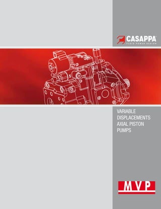
VARIABLE
DISPLACEMENTS
AXIAL PISTON
PUMPS
2. O
MVP
2 DCAT048-ID02
O
07/03.2022
O Modification from former edition.
INDEX
Section Page
INTRODUCTION..................................................................................................................................................................3
GENERAL INFORMATION / INSTRUCTIONS.......................................................................................................................4
MOUNTING POSITIONS......................................................................................................................................................5
DISPLACEMENTS AND WORKING PRESSURES RANGE.....................................................................................................6
FEATURES..........................................................................................................................................................................7
DOUBLE SHAFT SEAL OPTION..........................................................................................................................................11
DISPLACEMENT SETTING.................................................................................................................................................12
CENTER OF GRAVITY........................................................................................................................................................12
OPERATING CURVES.........................................................................................................................................................13
SINGLE PUMPS AND COMMON INLET MULTIPLE PUMPS
DIMENSIONS....................................................................................................................................................................20
DRIVE SHAFTS..................................................................................................................................................................32
MOUNTING FLANGES........................................................................................................................................................36
PORTS TYPE.....................................................................................................................................................................38
REGULATORS....................................................................................................................................................................41
MULTIPLE PUMPS WITH THROUGH DRIVE.......................................................................................................................53
HOW TO ORDER................................................................................................................................................................64
Replaces:
06/06.2020
3. MVP
3
DCAT048-ID02
6
5
4
3
2
1
7
8
9
10
11
06/06.2020
Variable displacement axial piston pumps swash plate design ideally suited for medium and high pressure open
circuit applications. The compact design allows to be mounted directly on engine motors.
DISPLACEMENTS
From 14 cm3
/rev (0.85 in3
/rev)
To 84,7 cm3
/rev (5.17 in3
/rev)
PRESSURE
Max. constant operating pressure 280 bar (4060 psi)
Max. system pressure (relief valve setting) 315 bar (4568 psi)
Max. peak of pressure 350 bar (5075 psi)
SPEED
Max. 3500 min-1
APPLICATION
Medium, high pressure
SECTOR
Mobile
TYPICAL APPLICATIONS
z Skid Steer Loaders
z Wheel Loaders - Backhoe Loaders
z Mini and Midi-Excavators
z Telehandlers
z Forklifts
z Windmills - Green Energy
z Tractors & Attachements
1 Pump body
2 Swash plate
3 Cylinders block
4 Counterbalancing spring
5 Plug
6 Max. displacement limiter
7 Cover
8 Valve plate
9 Min. displacement limiter
10 Piston
11 Piston guide plate
z Compact design
z Longer service life
z Low noise emission
z Max. and min. displacement limiter
z Drive shaft bearing suitable for radial and axial loads
z Hydraulic and Electro-hydraulic displacement controls
INTRODUCTION
4. MVP
4 DCAT048-ID02
GENERAL INFORMATION / INSTRUCTIONS
DIRECTION OF ROTATION
Clockwise or anti-clockwise defined looking at the drive shaft.
HYDRAULIC FLUID
Mineral oil based hydraulic fluid conforming to DIN 51524,
fire resistant fluids and biodegradable fluids according to the
technical data shown in the tables on pages 7 ÷ 9. The system
should be designed to prevent aeration of the hydraulic fluid.
FLUID VISCOSITY
The fluid viscosity range for optimal use of MVP pump is
between 15 and 35 cSt (77 and 163 SSU).
Functional limit conditions are:
max.: 1500 cSt (6818 SSU) at start up at minimum tempera
ture of -25 °C (-13 °F) with straight and short inlet line.
min.: 10 cSt (58 SSU) at maximum temperature of 110 °C
(230 °F)
FILTRATION
To ensure the optimal performance and the maximum life to
the pump, the hydraulic fluid must have and maintain a fluid
contamination within the values shown in the table below.
Working pressure
bar (psi)
Δp < 140
(2030)
140 < Δp < 210
(2030) (3045)
Δp > 210
(3045)
Contamination
class NAS 1638
9 8 7
Contamination
class ISO
4406:1999
20/18/15 19/17/14 18/16/13
Achieved with
filter ßx(c)
≥75
according to ISO
16889
10 μm 10 μm 10 μm
Casappa recommends to use its own
production filters:
STORAGE
The storage must be in a dry environment.
Max storage time in ideal conditions is 24 months.
The ideal storage temperature is between 5 °C (41 °F) and
20 °C (68 °F). No problem in case of temperature between
-40 °C (-40 °F) and 50 °C (122 °F). Below -40 °C (-40 °F) plea-
se consult our pre-sales department.
INSTALLATION
Check that the maximum coupling eccentricity stays within
0,25 mm (0.0098 in) to reduce shaft loads due to misalign-
ment. It is advised to use a flexible coupling suitable to absorb
eventual rotational shocks. For applications with axial and ra-
dial loads exceeding published standards, consult our sales
department. The direction of rotation of the pump must agree
with the prime mover rotation. Before installation, the case of
the pump must be filled with fluid.
LINES
The lines must have a major diameter which is at least as large
as the diameter of pump ports, and must be perfectly sealed.
To reduce loss of power, the lines should be as short as possi-
ble, reducing the sources of hydraulic resistance (elbow, throt-
tling, gate valves, etc.) to a minimum. A length of flexible tub-
ing is recommended to reduce the transmission of vibrations.
Before connecting the lines, remove any plug and make sure
that the lines are perfectly clean. Check that the drain line is
dimensioned in a way to guarantee a case pressure lower than
1,5 bar (22 psi) absolute. The drain line must be connected
directly (no filter, no valves, no oil cooler) to the tank and must
terminate below the oil level. Check that the dimensions of the
suction line guarantee a pressure equal or superior to 0,8 bar
(12 psi). Inlet pressure less than 0,8 bar (12 psi) could cause an
increase of noise emission, the decrease of the pump perfor-
mances and a reduction of its life expectancy.
STARTING UP
Check that all connections are secure and that the entire sys-
tem is completely clean. Add oil to the tank always using a
filter. Bleed the air from the circuit to help the filling. Turn on
the system for a few moments at minimum speed, then bleed
the circuit again and check the level of oil in the tank. Gradually
increase the pressure and speed of rotation up to the pre-set
operating levels, which must stay within the stated limits as
specified in the catalogue.
FOR VERY LOW TEMPERATURE
STARTING UP
We strongly recommend to warm up the oil before running the
machine. If this is not possible, the warm up of the oil and of
the pump should be carried out following these instructions:
• Start the pump in stand-by condition at minimum speed.
Keep this working condition until the pump case reaches
-20 °C (-4 °F)
• Increase slowly the displacement.Max pressure permitted:
50 bar (725 psi). The maximum permitted speed is strictly
connected to the layout of the inlet circuit; check that there
is no cavitation before increasing the speed.
• Keep this working condition until the oil temperature in the
whole system is -10 °C (14 °F).
• Maximum pressure can be achieved from now on.
• Always check the outlet flow to prevent cavitation damage.
All the temperature are referred to oil with viscosity ISO VG 32
according to DIN 51 519.
SUGGESTIONS
To prevent cavitation at low temperature we suggest:
• To warm up the tank
• To pressurize the tank
• To oversize the inlet hose
05/10.2014
5. MVP
5
DCAT048-ID02
06/06.2020
MOUNTING POSITIONS
Standard pump is supplied with D1 drain hole open and D2,
D3, D4 plugged (u if available).
Before installation fill the pump with hydraulic oil for at least
3/4 of the volume keeping it in horizontal position.
The pump can be mounted in a horizontal or vertical position.
The highest of the case drain ports must be used to keep the
required filling oil.
If D1 is not the highest drain port it must be closed by moving
the plug from the hole chosen for the drain line.
The pump can be located above the oil level if the absolute
pressure at the inlet port stays within the stated limits.
With exception of pump mounted below the oil level, we rec-
ommend to interpose a baffle plate between inlet and drain
line.
To reduce further noise emission, we recommend to mount
the pump below the oil level and avoid suction lines with sharp
restrictions.
HORIZONTAL MOUNTING VERTICAL MOUNTING
Arrangement inside the tank.
Minimum oil level equal or above
the pump mounting face.
A ≥ 200 mm (7.874 in)
Arrangement inside the tank.
Minimum oil level equal or above
the pump mounting face.
A ≥ 200 mm (7.874 in)
Arrangement inside the tank.
Minimum oil level below the
pump mounting face.
Min. inlet pressure= 0,8 bar abs
(24 in Hg)
B ≤ 800 mm (31.4961 in)
C = 200 mm (7.874 in)
Arrangement inside the tank.
Minimum oil level below the
pump mounting face.
Min. inlet pressure= 0,8 bar abs
(24 in Hg)
B ≤ 800 mm (31.4961 in)
C = 200 mm (7.874 in)
Arrangement outside the tank above
oil level.
Min. inlet pressure= 0,8 bar abs
(24 in Hg)
B ≤ 800 mm (31.4961 in)
C = 200 mm (7.874 in)
Arrangement outside the tank above
oil level.
Min. inlet pressure= 0,8 bar abs
(24 in Hg)
B ≤ 800 mm (31.4961 in)
C = 200 mm (7.874 in)
Arrangement outside the tank
below oil level.
C = 200 mm (7.874 in)
IN= inlet line - D1= drain line - A= min. distance between the line - B+C= permissible suction height - C= line immersion depth
6. MVP
6 DCAT048-ID02
p
p
(
(
b
b
a
a
r
r
)
)
-
-
(
(
p
p
s
s
i
i
)
)
T
T (
(s
s)
)
p
p1
1
p
p2
2
p
p3
3
M
Ma
ax
x.
. 2
20
0 s
s M
Ma
ax
x.
. 5
50
0 m
ms
s
DISPLACEMENTS AND WORKING PRESSURES RANGE
MVPD 30
MVP 30
MVPD 48
MVP 48
MVP 60
14
(0.85)
34
(2.07)
28
(1.71) 45
(2.75)
53
(3.23)
65
(3.97)
72
(4.39)
84
(5.12)
Working pressure
bar (psi)
Pump
series
Max. displacement
cm3
/rev (in3
/rev)
p1 - p3 p1 - p3 p1 - p3
230
(3335)
-
290
(4205)
280
(4060)
-
350
(5075)
250
(3625)
-
315
(4568)
: MVPD Series. For more information please consult the respective technical catalogue.
MVP-MVPD Comparison
PRESSURE DEFINITION
p1
Constant operating pressure
p2
System pressure (relief valve setting)
p3
Peak of pressure
The peak of pressure is the max pressure allowed and
it corresponds to the overshoot of the relief valve.
Please note that both relief valve setting and overshoot
must be lower than their limits.
If the relief setting is compliant but the overshoot is hi-
gher than the limit, the relief setting must be decreased
until the overshoot is compliant to Casappa limit.
Please contact us for high frequency applications.
06/06.2020
7. O
O
MVP
7
DCAT048-ID02
FEATURES
Technical data with mineral oil
HL or HLP mineral oil based hydraulic fluid to DIN 51524
Pump type MVP 30·28 30·34 48·45 48·53 60·60 60·72 60·84
Max. displacment
(theor.) Vmax
cm3
/rev
(in3
/rev)
28
(1.71)
34,8
(2.12)
45
(2.75)
53,7
(3.28)
60
(3.66)
72
(4.39)
84,7
(5.17)
Inlet pressure
bar abs.
(in Hg)
min.
0.8
(24)
bar abs.
(psi)
max.
25
(363)
Max. outlet
pressure pmax
bar
(psi)
p1
280
(4060)
250
(3625)
280
(4060)
250
(3625)
280
(4060)
280
(4060)
250
(3625)
p2
315
(4568)
280
(4060)
315
(4568)
280
(4060)
315
(4568)
315
(4568)
280
(4060)
p3
350
(5075)
315
(4568)
350
(5075)
315
(4568)
350
(5075)
350
(5075)
315
(4568)
Max. drain line
pressure
bar abs.
(psi)
1,5
(22)
Max. speed nmax
min-1
@ Vmax
(1) 3500 2900 3000 2500 3000 2700 2300
Max. delivery
(theor.)
l/min
(US gpm)
@ nmax
98
(25.9)
101
(26.7)
135
(35.7)
134
(35.4)
180
(47.6)
194
(51.3)
194
(51.3)
@ 2000 min-1 56
(14.8)
70
(18.5)
90
(23.8)
107
(28.3)
120
(31.7)
144
(38.0)
169
(44.7)
@ 1500 min-1 42
(11.1)
52
(13.7)
68
(18.0)
81
(21.4)
90
(23.8)
108
(28.5)
127
(33.6)
Max. power
(theor.)
(Δp = pmax
cont.)
kW
(HP)
@ nmax
45,7
(61.2)
42,1
(56.4)
63
(84.4)
55,9
(74.9)
84
(112.6)
90,7
(121.5)
81
(108.5)
@ 2000 min-1 26,1
(35.0)
29
(38.9)
42
(56.3)
44,8
(60.0)
56
(75.0)
67,2
(90.0)
70,6
(94.6)
@ 1500 min-1 19,6
(26.3)
21,8
(29.2)
31,5
(42.2)
33,6
(45.0)
42
(56.3)
50,4
(67.5)
52,9
(70.9)
Max. torque
(theor.)
Nm
(lbf in)
@ pmax
cont.
124,8
(1105)
138,5
(1226)
200,5
(1775)
213,7
(1891)
267,4
(2367)
320,9
(2840)
337
(2983)
@ 100 bar
(1450 psi)
44,6
(395)
55,4
(490)
71,6
(634)
85,5
(757)
95,5
(845)
114,6
(1014)
134,8
(1193)
Moment of inertia
rotary group
kgm2
(ft2
lbs)
0,002
(0.05)
0,002
(0.05)
0,003
(0.07)
0,003
(0.07)
0,008
(0.19)
0,008
(0.19)
0,008
(0.19)
Fill volume
l
(US gallons)
0,85
(0.22)
0,85
(0.22)
1
(0.26)
1
(0.26)
1,3
(0.34)
1,3
(0.34)
1,3
(0.34)
Mass (approx.)
kg
(lbs)
15
(33.1)
15
(33.1)
19
(41.9)
19
(41.9)
22
(48.5)
22
(48.5)
22
(48.5)
Seals N= Buna V= Viton
Operating
temperature
°C
(°F)
min.
-25
(-13)
-15
(5)
max. cont.
80
(176)
110
(230)
max. peak
100
(212)
125
(257)
(1) = with an inlet pressure of 1 bar abs (14.5 psi) and viscosity between 15 and 35 cSt (77 and 163 SSU).
Reducing the displacement or increasing the inlet pressure the max. speed changes. See table at page 10.
Max. speed limit are: MVP 30: 3500 m-1
– MVP 48: 3000 m-1
- MVP 60: 3000 m-1
Please contact us for different working conditions.
O
07/03.2022
Replaces:
06/06.2020
8. MVP
8 DCAT048-ID02
FEATURES
Technical data restrictions with fire resistant fluid
HFA - Oil emulsion in water (5 ÷ 15 % of oil)
(1) = with an inlet pressure of 1 bar abs (14.5 psi) and
viscosity between 15 and 35 cSt (77 and 163 SSU).
Pump type MVP 30·28 30·34 48·45 48·53 60·60 60·72 60·84
Max. outlet
pressure pmax
bar (psi)
p1
140 (2030)
p2
150 (2175)
p3
160 (2320)
Max. speed nmax
min-1
@ Vmax
(1) 2200 1800 2000 1700 2000 1700 1500
Seals N= Buna
Operating
temperature
°C (°F)
min. 2 (36)
max. 55 (131)
Bearing life
(ref. mineral oil)
% 20 %
HFB - Water emulsion in oil (40 % of water)
Pump type MVP 30·28 30·34 48·45 48·53 60·60 60·72 60·84
Max. outlet
pressure pmax
bar (psi)
p1 160 (2320)
p2 170 (2465)
p3 180 (2610)
Max. speed nmax
min-1
@ Vmax
(1) 2350 1900 2150 1800 2150 1800 1600
Seals N= Buna
Operating
temperature
°C (°F)
min. 2 (36)
max. 60 (140)
Bearing life
(ref. mineral oil)
% 40 %
HFC - Water-glycol (35 ÷ 55 % of water)
Pump type MVP 30·28 30·34 48·45 48·53 60·60 60·72 60·84
Max. outlet
pressure pmax
bar (psi)
p1 180 (2610)
p2 195 (2828)
p3 210 (3045)
Max. speed nmax
min-1
@ Vmax
(1) 2350 1900 2150 1800 2150 1800 1600
Seals N= Buna
Operating
temperature
°C (°F)
min. -10 (14)
max. 60 (140)
Bearing life
(ref. mineral oil)
% 40 %
05/10.2014
9. MVP
9
DCAT048-ID02
05/10.2014
FEATURES
Technical data restrictions with fire resistant fluid
(1) = with an inlet pressure of 1 bar abs (14.5 psi) and
viscosity between 15 and 35 cSt (77 and 163 SSU).
Pump type MVP 30·28 30·34 48·45 48·53 60·60 60·72 60·84
Max. outlet
pressure pmax
bar (psi)
p1
200 (2900)
p2
220 (3190)
p3
240 (3480)
Max. speed nmax
min-1
@ Vmax
(1) 2350 1900 2150 1800 2150 1800 1600
Seals V= Viton
Operating
temperature
°C (°F)
min. -10 (14)
max. 80 (176)
Bearing life
(ref. mineral oil)
% 90 %
Technical data restrictions with biodegradable fluids
HETG - Natural based fluid (the water content must never exceed 0,1 %)
Pump type MVP 30·28 30·34 48·45 48·53 60·60 60·72 60·84
Max. outlet
pressure pmax
bar (psi)
p1
180 (2610)
p2
195 (2828)
p3
210 (3045)
Max. speed nmax
min-1
@ Vmax
(1) 2350 1900 2150 1800 2150 1800 1600
Seals N= Buna
Operating
temperature
°C (°F)
min. -10 (14)
max. 60 (140)
Bearing life
(ref. mineral oil)
% 50 %
HEPG - Polyglycol based synthetic fluid (the water content must never exceed 0,1 %)
Pump type MVP 30·28 30·34 48·45 48·53 60·60 60·72 60·84
Max. outlet
pressure pmax
bar (psi)
p1
180 (2610)
p2
195 (2828)
p3
210 (3045)
Max. speed nmax
min-1
@ Vmax
(1) 2350 1900 2150 1800 2150 1800 1600
Seals V= Viton
Operating
temperature
°C (°F)
min. -15 (5)
max. 90 (194)
Bearing life
(ref. mineral oil)
% 75 %
HEES - Synthetic esters (the water content must never exceed 0,1 %)
Pump type MVP 30·28 30·34 48·45 48·53 60·60 60·72 60·84
Seals V= Viton
Operating
temperature
°C (°F)
min. -15 (5)
max. 80 (176)
Bearing life
(ref. mineral oil)
% 100 %0
10. MVP
10 DCAT048-ID02
FEATURES
Design calculations for pump
Q l/min (US gpm) Flow
M Nm (lbf in) Torque
P kW (HP) Power
V cm3
/rev (in3
/rev) Displacement
n min-1
Speed
Δp bar (psi) Pressure
ηv
= ηv
(V, Δp, n) Volumetric efficiency
ηhm
= ηhm
(V, Δp, n) Hydro-mechanical efficiency
ηt
= ηv
• ηhm
Overall efficiency
Max. permissible load on drive shaft
Pump type
MVP
30•28
MVP
30•34
MVP
48•45
MVP
48•53
MVP
60•60
MVP
60•72
MVP
60•84
Fax
Axial force
N
(lbf)
1000
(225)
1000
(225)
1500
(337)
1500
(337)
2000
(450)
2000
(450)
2000
(450)
Frad
Radial force @ L/2
N
(lbf)
1500
(337)
1500
(337)
1500
(337)
1500
(337)
3000
(675)
3000
(675)
3000
(675)
% Variation of the max. speed in relation of the inlet pressure and/or displacement reduction
Inlet
pressure
Displacement %
psi (bar abs) 65 70 80 90 100
12 (0,8) 120 115 105 97 90
%
Variation
of
the
max.
speed
13 (0,9) 120 120 110 103 95
14.5 (1,0) 120 120 115 107 100
17 (1,2) 120 120 120 113 106
20 (1,4) 120 120 120 120 112
23 (1,6) 120 120 120 120 117
29 (2,0) 120 120 120 120 120
Example 1
Displacement: 100 %
Speed: 100 %
Inlet pressure: 1,0 bar abs. (14.5 psi)
Example 2
Displacement: 80 %
Inlet pressure: 1,0 bar abs. (14.5 psi)
Speed: 115 %
Max. speed must not exceed the limits specified at page 7.
Q = Q theor.
• ηv
[l/min]
Qtheor.
=
V (cm3
/rev) • n (min-1
)
1000
M =
M theor.
[Nm]
ηhm
Mtheor.
=
Δp (bar) • V (cm3
/rev)
62,83
PIN
=
P OUT
[kW]
ηt
POUT
=
Δp (bar) • Q (l/min)
600
03/06.2011
11. O
MVP
11
DCAT048-ID02
FEATURES
Side ports Rear ports
Anti-clockwise rotation
Clockwise rotation
Side ports Rear ports
Definition of rotation direction looking at the drive shaft
D0UBLE SHAFT SEAL OPTION
Pump
type
MOUNTING FLANGES
S1 S5 S7 S8
MVP30 x x
MVP48 x
MVP60 x x
X Available combination
The double shaft seal is available for the following
configuration:
O
07/03.2022
Replaces:
03/06.2011
12. MVP
12 DCAT048-ID02
L CG1
L INT L CG2
MVP30 MVP48 MVP60
Max. displacement setting range
cm3
/rev
(in3
/rev)
from 17,4 (1.06) 34,9 (2.13) 55 (3.36)
to 34,8 (2.12) 53,7 (3.28) 84,7 (5.17)
Min. displacement setting range
cm3
/rev
(in3
/rev)
from 0 0 0
to 17,4 (1.06) 10,7 (0.65) 38,1 (2.32)
One turn of screw changes pump
displacement by approximately
cm3
/rev
(in3
/rev)
E 2,8 (0.17) 3,2 (0.20) 5,0 (0.31)
F 2,3 (0.14) 3,0 (0.18) 4,2 (0.26)
Please contact us for different setting range.
Max.displacement
limiter
Min. displacement
limiter
Max. displacement
limiter
CENTER OF GRAVITY
Center of gravity
M MF
=
L CG1
• m1
+ (L INT
+ L CG2
) • m2
[Nm]
102
MMF
: Load moment on mounting flange
L CG
: Distance from center of gravity to moun-
ting flange [mm]
m : Weight (kg)
MVP30 MVP48 MVP60
L CG1
mm (in) 100 (3.94) 116 (4.57) 120 (4.72)
L CG2
mm (in) 90 (3.54) 99 (3.90) 107 (4.21)
L INT
mm (in) 208 (8.19) 233 (9.17) 253 (9.96)
For single pumps refer to L CG2
values
Avarage data, please contact us for specific values.
Special body without Min. displacement
limiter is available only on request, please
contact us for more information
Tightening torque 15±1
Nm (124 ÷ 142 lbf in)
E: Max. displacement limiter (Min displace-
ment limiter is plugged)
G: Min. and Max. displacement limiter
DISPLACEMENT SETTING
06/06.2020
13. MVP
13
DCAT048-ID02
120
(31.7)
0
100
(26.4)
80
(21.1)
40
(10.6)
60
(15.9)
20
(5.3)
0
10
(13.4)
60
(80.4)
50
(67.0)
40
(53.6)
20
(26.8)
30
(40.2)
P
[kW]
-
[(HP)]
0
p [bar] - [(psi)]
300
(4350)
200
(2900)
150
(2175)
100
(1450)
50
(725)
250
(3625)
Q
[l/min]
-
[(US
gpm)]
(1)
(2)
(3)
(1)
(2)
(3)
1000 3500
3000
2500
2000
1500
280
(4060)
250
(3625)
150
(2175)
200
(2900)
100
(1450)
-1
n [min ]
p
[bar]
-
[(psi)]
50
(725)
1000 3500
3000
2500
2000
1500
280
(4060)
250
(3625)
150
(2175)
200
(2900)
100
(1450)
-1
n [min ]
p
[bar]
-
[(psi)]
50
(725)
0
54
300
(4350)
p [bar] - [(psi)]
69
66
63
60
78
72
75
[dB(A)]
200
(2900)
150
(2175)
100
(1450)
50
(725)
250
(3625)
57
(1)
(1)
(2)
(2)
MVP30•28 OPERATING CURVES
Each curve has been obtained at 50 °C (122 °F), using oil with viscosity 46 cSt (210 SSU) at 40 °C (104 °F) and at
these speed: (1) 1500 min-1
(2) 2000 min-1
(3) 3500 min-1
Delivery / power
@ max. displacement
Noise level Distance from microphone to
pump = 1 m (39.37 in)
@ max. displacement @ min. displacement
Volumetric efficiency
@ max. displacement
Overall efficiency
@ max. displacement
Values shown in the diagrams are indicative only. Actual values may vary depending on the pump configuration.
06/06.2020
14. MVP
14 DCAT048-ID02
Q
[l/min]
-
[(US
gpm)]
120
(31.7)
0
100
(26.4)
80
(21.1)
40
(10.6)
60
(15.9)
20
(5.3)
0
10
(13.4)
60
(80.4)
50
(67.0)
40
(53.6)
20
(26.8)
30
(40.2)
P
[kW]
-
[(HP)]
(1)
(2)
(3)
(1)
(2)
(3)
0
p [bar] - [(psi)]
300
(4350)
200
(2900)
150
(2175)
100
(1450)
50
(725)
250
(3625)
0
54
300
(4350)
p [bar] - [(psi)]
69
66
63
60
78
72
75
[dB(A)]
200
(2900)
150
(2175)
100
(1450)
50
(725)
250
(3625)
57
(1)
(1)
(2)
(2)
1000 2900
2500
2000
1500
250
(3625)
150
(2175)
200
(2900)
100
(1450)
-1
n [min ]
p
[bar]
-
[(psi)]
50
(725)
1000 2900
2500
2000
1500
250
(3625)
150
(2175)
200
(2900)
100
(1450)
-1
n [min ]
p
[bar]
-
[(psi)]
50
(725)
MVP30•34 OPERATING CURVES
Each curve has been obtained at 50 °C (122 °F), using oil with viscosity 46 cSt (210 SSU) at 40 °C (104 °F) and at
these speed: (1) 1500 min-1
(2) 2000 min-1
(3) 2900 min-1
Delivery / power
@ max. displacement
Noise level Distance from microphone to
pump = 1 m (39.37 in)
@ max. displacement @ min. displacement
Volumetric efficiency
@ max. displacement
Overall efficiency
@ max. displacement
Values shown in the diagrams are indicative only. Actual values may vary depending on the pump configuration.
06/06.2020
15. MVP
15
DCAT048-ID02
P
[kW]
-
[(HP)]
Q
[l/min]
-
[(US
gpm)]
0
0
300
(4350)
p [bar] - [(psi)]
100
(26.4)
80
(21.1)
40
(10.6)
60
(15.9)
20
(5.3)
10
(13.4)
50
(67.0)
40
(53.6)
20
(26.8)
30
(40.2)
160
(42.3)
8
80
0
(
(1
10
07
7.
.2
2)
)
120
(31.7)
60
(80.4)
140
(37.0)
70
(93.8)
0
200
(2900)
150
(2175)
100
(1450)
50
(725)
250
(3625)
(1)
(2)
(3)
(1)
(2)
(
3
)
0
57
300
(4350)
p [bar] - [(psi)]
69
66
63
60
78
72
75
[dB(A)]
200
(2900)
150
(2175)
100
(1450)
50
(725)
250
(3625)
(1)
(2)
(1)
(2)
1000 3000
2500
2000
1500
280
(4060)
250
(3625)
150
(2175)
200
(2900)
100
(1450)
-1
n [min ]
p
[bar]
-
[(psi)]
50
(725)
1000 3000
2500
2000
1500
280
(4060)
250
(3625)
150
(2175)
200
(2900)
100
(1450)
-1
n [min ]
p
[bar]
-
[(psi)]
50
(725)
MVP48•45 OPERATING CURVES
Each curve has been obtained at 50 °C (122 °F), using oil with viscosity 46 cSt (210 SSU) at 40 °C (104 °F) and at
these speed: (1) 1500 min-1
(2) 2000 min-1
(3) 3000 min-1
Delivery / power
@ max. displacement
Noise level Distance from microphone to
pump = 1 m (39.37 in)
@ max. displacement @ min. displacement
Volumetric efficiency
@ max. displacement
Overall efficiency
@ max. displacement
Values shown in the diagrams are indicative only. Actual values may vary depending on the pump configuration.
06/06.2020
16. MVP
16 DCAT048-ID02
P
[kW]
-
[(HP)]
Q
[l/min]
-
[(US
gpm)]
0
0
(1)
(2)
(3)
(1)
(
2
)
(3)
0
p [bar] - [(psi)]
300
(4350)
200
(2900)
150
(2175)
100
(1450)
50
(725)
250
(3625)
100
(26.4)
80
(21.1)
40
(10.6)
60
(15.9)
20
(5.3)
10
(13.4)
50
(67.0)
40
(53.6)
20
(26.8)
30
(40.2)
160
(42.3)
80
(107.2)
120
(31.7)
60
(80.4)
140
(37.0)
70
(93.8)
0
57
300
(4350)
p [bar] - [(psi)]
69
66
63
60
78
72
75
[dB(A)]
200
(2900)
150
(2175)
100
(1450)
50
(725)
250
(3625)
(1)
(2)
(1)
(2)
1000 2500
2000
1500
250
(3625)
150
(2175)
200
(2900)
100
(1450)
-1
n [min ]
p
[bar]
-
[(psi)]
50
(725)
1000 2500
2000
1500
250
(3625)
150
(2175)
200
(2900)
100
(1450)
-1
n [min ]
p
[bar]
-
[(psi)]
50
(725)
MVP48•53 OPERATING CURVES
Each curve has been obtained at 50 °C (122 °F), using oil with viscosity 46 cSt (210 SSU) at 40 °C (104 °F) and at
these speed: (1) 1500 min-1
(2) 2000 min-1
(3) 2500 min-1
Delivery / power
@ max. displacement
Noise level Distance from microphone to
pump = 1 m (39.37 in)
@ max. displacement @ min. displacement
Volumetric efficiency
@ max. displacement
Overall efficiency
@ max. displacement
Values shown in the diagrams are indicative only. Actual values may vary depending on the pump configuration.
06/06.2020
17. MVP
17
DCAT048-ID02
P
[kW]
-
[(HP)]
Q
[l/min]
-
[(US
gpm)]
0
0
300
(4350)
p [bar] - [(psi)]
80
(21.1)
40
(10.6)
40
(53.6)
20
(26.8)
200
(52.8)
100
(134.0)
120
(31.7)
60
(80.4)
0
200
(2900)
150
(2175)
100
(1450)
50
(725)
250
(3625)
(1)
(2)
(3)
(1)
(2)
(
3
)
160
(42.3)
80
(107.2)
0
60
300
(4350)
p [bar] - [(psi)]
72
69
66
63
81
75
78
[dB(A)]
200
(2900)
150
(2175)
100
(1450)
50
(725)
250
(3625)
(1)
(2)
(1)
(2)
1000 3000
2500
2000
1500
280
(4060)
250
(3625)
150
(2175)
200
(2900)
100
(1450)
-1
n [min ]
p
[bar]
-
[(psi)]
50
(725)
1000 3000
2500
2000
1500
280
(4060)
250
(3625)
150
(2175)
200
(2900)
100
(1450)
-1
n [min ]
p
[bar]
-
[(psi)]
50
(725)
MVP60•60 OPERATING CURVES
Each curve has been obtained at 50 °C (122 °F), using oil with viscosity 46 cSt (210 SSU) at 40 °C (104 °F) and at
these speed: (1) 1500 min-1
(2) 2000 min-1
(3) 3000 min-1
Delivery / power
@ max. displacement
Noise level Distance from microphone to
pump = 1 m (39.37 in)
@ max. displacement @ min. displacement
Volumetric efficiency
@ max. displacement
Overall efficiency
@ max. displacement
Values shown in the diagrams are indicative only. Actual values may vary depending on the pump configuration.
06/06.2020
18. MVP
18 DCAT048-ID02
P
[kW]
-
[(HP)]
Q
[l/min]
-
[(US
gpm)]
0
0
300
(4350)
p [bar] - [(psi)]
100
(26.4)
75
(19.8)
50
(13.2)
25
(6.6)
15
(20.1)
60
(80.4)
45
(60.3)
30
(40.2)
175
(46.2)
105
(140.7)
125
(33.0)
75
(100.5)
150
(39.6)
90
(120.6)
0
200
(2900)
150
(2175)
100
(1450)
50
(725)
250
(3625)
(1)
(2)
(3)
(1)
(
2
)
(
3
)
0
60
300
(4350)
p [bar] - [(psi)]
72
69
66
63
81
75
78
[dB(A)]
200
(2900)
150
(2175)
100
(1450)
50
(725)
250
(3625)
(1)
(2)
(1)
(2)
1
10
00
00
0 2700
2500
2000
1500
280
(4060)
250
(3625)
150
(2175)
200
(2900)
100
(1450)
-1
n [min ]
p
[bar]
-
[(psi)]
50
(725)
1000 2700
2500
2000
1500
280
(4060)
250
(3625)
150
(2175)
200
(2900)
100
(1450)
-1
n [min ]
p
[bar]
-
[(psi)]
50
(725)
MVP60•72 OPERATING CURVES
Each curve has been obtained at 50 °C (122 °F), using oil with viscosity 46 cSt (210 SSU) at 40 °C (104 °F) and at
these speed: (1) 1500 min-1
(2) 2000 min-1
(3) 2700 min-1
Delivery / power
@ max. displacement
Noise level Distance from microphone to
pump = 1 m (39.37 in)
@ max. displacement @ min. displacement
Volumetric efficiency
@ max. displacement
Overall efficiency
@ max. displacement
Values shown in the diagrams are indicative only. Actual values may vary depending on the pump configuration.
06/06.2020
19. MVP
19
DCAT048-ID02
P
[kW]
-
[(HP)]
Q
[l/min]
-
[(US
gpm)]
0
0
(1)
(2)
(3)
(1)
(
2
)
(
3
)
0
p [bar] - [(psi)]
300
(4350)
200
(2900)
150
(2175)
100
(1450)
50
(725)
250
(3625)
80
(21.1)
40
(10.6)
40
(53.6)
20
(26.8)
200
(52.8)
100
(134.0)
120
(31.7)
60
(80.4)
160
(42.3)
80
(107.2)
0
60
300
(4350)
p [bar] - [(psi)]
72
69
66
63
81
75
78
[dB(A)]
200
(2900)
150
(2175)
100
(1450)
50
(725)
250
(3625)
(1)
(2)
(1)
(2)
1
10
00
00
0 2
23
30
00
0
2
20
00
00
0
1
15
50
00
0
2
25
50
0
(
(3
36
62
25
5)
)
1
15
50
0
(
(2
21
17
75
5)
)
2
20
00
0
(
(2
29
90
00
0)
)
1
10
00
0
(
(1
14
45
50
0)
)
-
-1
1
n
n [
[m
mi
in
n ]
]
p
p
[
[
b
b
a
a
r
r
]
]
-
-
[
[
(
(
p
p
s
s
i
i
)
)
]
]
5
50
0
(
(7
72
25
5)
)
1000 2300
2000
1500
250
(3625)
150
(2175)
200
(2900)
100
(1450)
-1
n [min ]
p
[bar]
-
[(psi)]
50
(725)
MVP60•84 OPERATING CURVES
Each curve has been obtained at 50 °C (122 °F), using oil with viscosity 46 cSt (210 SSU) at 40 °C (104 °F) and at
these speed: (1) 1500 min-1
(2) 2000 min-1
(3) 2300 min-1
Delivery / power
@ max. displacement
Noise level Distance from microphone to
pump = 1 m (39.37 in)
@ max. displacement @ min. displacement
Volumetric efficiency
@ max. displacement
Overall efficiency
@ max. displacement
Values shown in the diagrams are indicative only. Actual values may vary depending on the pump configuration.
06/06.2020
20. O
MVP
20 DCAT048-ID02
IN OUT
D1
(<)
(<)
(<)
MVP30 SIDE PORTS - DIMENSIONS L
Drive shafts: see page 32
Mounting flanges: see page 36
Ports: see page 38 ÷ 40
(n)
Dimension refer to S5 mounting flange.
For S1 flange add 27 mm (1.06 in).
O
07/03.2022
Replaces:
06/06.2020
21. O
MVP
21
DCAT048-ID02
D1
OUT
IN
(<)
IN
OUT
MVP30 SIDE PORTS - DIMENSIONS P
Drive shafts: see page 32
Mounting flanges: see page 36
Ports: see page 38 ÷ 40
(n)
Dimension refer to S5 mounting flange.
For S1 flange add 27 mm (1.06 in).
Anti-clockwise rotation
O
07/03.2022
Replaces:
06/06.2020
22. O
MVP
22 DCAT048-ID02
110 Nm
974 lbf in
OUT
IN
D1
(<)
(<)
(<)
(<)
(<)
(<)
MVP30/KP20 SIDE PORTS - DIMENSIONS L
Common inlet intermediate flange:
MVP code P7
KP20 code N5
Drive shafts: see page 32
Mounting flanges: see page 36
Ports: see page 38 ÷ 40
(n)
Dimension refer to S5 mounting flange.
For S1 flange add 27 mm (1.06 in).
Gear pump KAPPA 20 (for more information please see the respective technical catalogue)
Pump
type
4 6,3 8 11,2 14 16 20 Dimensions
MVP30
247,5
(9.74)
250
(9.84)
252,5
(9.94)
256
(10.08)
260
(10.24)
265,5
(10.45)
272
(10.71)
mm
(in)
A
218,5
(8.60)
221
(8.70)
223,5
(8.80)
227
(8.94)
225,5
(8.86)
231
(9.09)
237,5
(9.35)
mm
(in)
B
O
07/03.2022
Replaces:
06/06.2020
23. O
MVP
23
DCAT048-ID02
IN
110 Nm
974 lbf in
OUT
D1
(<)
(<)
(<)
(<)
(<)
(<)
MVP30/PHP20 SIDE PORTS - DIMENSIONS L
Common inlet intermediate flange:
MVP code I7
KP20 code S7
Drive shafts: see page 32
Mounting flanges: see page 36
Ports: see page 38 ÷ 40
Also available in
combination with PLP20
(n)
Dimension refer to S5 mounting flange.
For S1 flange add 27 mm (1.06 in).
O
07/03.2022
Gear pump POLARIS PH20 (for more information please see the respective technical catalogue)
Pump
type
8 10,5 11,2 14 16 18 19 20 23 24,5 25 27,8 31,5
Dimen-
sions
MVP30
274,6
(10.81)
278,6
(10.97)
279,1
(10.99)
284,1
(11.41)
287,6
(11.32)
289,8
(11.41)
291
(11.46)
294,1
(11.58)
297,6
(11.72)
299,9
(11.81)
301,6
(11.87)
304,4
(11.98)
311,6
(12.27)
mm
(in)
A
228
(8.98)
231
(9.09)
231,5
(9.11)
236,5
(9.31)
239,5
(9.43)
230,4
(9.07)
231
(9.09)
232,5
(9.15)
234,2
(9.22)
235,3
(9.26)
236,5
(9.31)
237,9
(9.36)
241,5
(9.51)
mm
(in)
B
Replaces:
06/06.2020
24. MVP
24 DCAT048-ID02
IN OUT
D1
MVP48 SIDE PORTS - DIMENSIONS L
Drive shafts: see page 33
Mounting flanges: see page 36
Ports: see page 38 ÷ 40
06/06.2020
26. MVP
26 DCAT048-ID02
IN
D1
110 Nm
974 lbf in
OUT
MVP48/KP20 SIDE PORTS - DIMENSIONS L
Common inlet intermediate flange:
MVP code P7
KP20 code N5
Drive shafts: see page 33
Mounting flanges: see page 36
Ports: see page 38 ÷ 40
Gear pump KAPPA 20 (for more information please see the respective technical catalogue)
Pump
type
4 6,3 8 11,2 14 16 20 Dimensions
MVP48
263
(10.35)
265,5
(10.45)
268
(10.55)
271,5
(10.69)
275,5
(10.85)
281
(11.06)
287,5
(11.32)
mm
(in)
A
234
(9.21)
236,5
(9.31)
239
(9.41)
242,5
(9.55)
241
(9.49)
246,5
(9.70)
253
(9.96)
mm
(in)
B
06/06.2020
27. MVP
27
DCAT048-ID02
IN
D1
110 Nm
974 lbf in
OUT
06/06.2020
MVP48/PHP20 SIDE PORTS - DIMENSIONS L
Common inlet intermediate flange:
MVP code I7
PHP20 code S7
Also available in
combination with PLP20
Drive shafts: see page 33
Mounting flanges: see page 36
Ports: see page 38 ÷ 40
Gear pump POLARIS PH20 (for more information please see the respective technical catalogue)
Pump
type
8 10,5 11,2 14 16 18 19 20 23 24,5 25 27,8 31,5
Dimen-
sions
MVP48
290,1
(11.42)
294,1
(11.58)
294,6
(11.60)
299,6
(11.80)
303,1
(11.93)
305,3
(12.02)
306,5
(12.07)
309,6
(12.19)
313,1
(12.33)
315,4
(12.42)
317,1
(12.48)
319,9
(12.59)
327,1
(12.88)
mm
(in)
A
243,5
(9.59)
246,5
(9.70)
247
(9.72)
252
(9.92)
255
(10.04)
245,9
(9.68)
246,5
(9.70)
248
(9.76)
249,7
(9.83)
250,8
(9.87)
252
(9.92)
253,4
(9.97)
257
(10.12)
mm
(in)
B
28. MVP
28 DCAT048-ID02
IN
D1
OUT
MVP60 SIDE PORTS - DIMENSIONS L
Drive shafts: see page 34 ÷ 35
Mounting flanges: see page 36 ÷ 37
Ports: see page 38 ÷ 40
06/06.2020
30. MVP
30 DCAT048-ID02
IN
D1
110 Nm
974 lbf in
OUT
Common inlet intermediate flange:
MVP code P7
KP20 code N5
Drive shafts: see page 34 ÷ 35
Mounting flanges: see page 36 ÷ 37
Ports: see page 38 ÷ 40
MVP60/KP20 SIDE PORTS - DIMENSIONS L
Gear pump KAPPA 20 (for more information please see the respective technical catalogue)
Pump
type
4 6,3 8 11,2 14 16 20 Dimensions
MVP60
301,3
(11.86)
303,8
(11.96)
306,3
(12.06)
309,8
(12.20)
313,8
(12.35)
319,3
(12.57)
325,8
(12.83)
mm
(in)
A
272,3
(10.72)
274,8
(10.82)
277,3
(10.92)
280,8
(11.06)
279,3
(11.00)
284,8
(11.21)
291,3
(11.47)
mm
(in)
B
06/06.2020
31. MVP
31
DCAT048-ID02
IN
D1
110 Nm
974 lbf in
OUT
06/06.2020
Common inlet intermediate flange:
MVP code I7
KP20 code S7
Drive shafts: see page 34 ÷ 35
Mounting flanges: see page 36 ÷ 37
Ports: see page 38 ÷ 40
MVP60/PHP20 SIDE PORTS - DIMENSIONS L
Also available in
combination with PLP20
Gear pump POLARIS PH20 (for more information please see the respective technical catalogue)
Pump
type
8 10,5 11,2 14 16 18 19 20 23 24,5 25 27,8 31,5
Dimen-
sions
MVP60
328,4
(12.93)
332,4
(13.09)
332,9
(13.11)
337,9
(13.30)
341,4
(13.44)
343,6
(13,53)
344,8
(13.57)
347,9
(13.70)
351,4
(13.83)
353,7
(13.93)
355,4
(13.99)
358,2
(14.10)
365,4
(14.39)
mm
(in)
A
281,8
(11.09)
284,8
(11.21)
285,3
(11.23)
290,3
(11.43)
293,3
(11.55)
284,2
(11.19)
284,8
(11.21)
286,3
(11.27)
288
(11.34)
289,1
(11.38)
290,3
(11.43)
291,7
(11.48)
295,3
(11.63)
mm
(in)
B
32. O
O
O
MVP
32 DCAT048-ID02
110 Nm
973 lbf in
170 Nm
1505 lbf in
210 Nm
1858 lbf in
290 Nm
2566 lbf in
270 Nm
2389 lbf in
MVP30 DRIVE SHAFTS
SAE “B” SPLINE 04
Mounting face refers to flange code S5
SAE “B” SPLINE 4R
Mounting face refers to flange code S5
SAE “B” STRAIGHT 32
Mounting face refers to flange code S5
Please contact us for different drive shafts.
SAE SPLINE 07
Mounting face refers to flange code S1
SAE “A” SPLINE 03
Mounting face refers to flange code S1
Ext. Involute Spline ANSI B92.1
with major diameter modified
13 teeth - 16/32 Pitch - 30 deg
Flat root - Side fit - Class 6
Ext. Involute Spline ANSI B92.1
with major diameter modified
11 teeth - 16/32 Pitch - 30 deg
Flat root - Side fit - Class 6
Ext. Involute Spline SAE J498B
with major diameter modified
9 teeth - 16/32 Pitch - 30 deg
Flat root - Side fit - Class 1
Ext. Involute Spline ANSI B92.1
with major diameter modified
13 teeth - 16/32 Pitch - 30 deg
Flat root - Side fit - Class 6
O
07/03.2022
Replaces:
06/06.2020
33. O
O
O
O
MVP
33
DCAT048-ID02
290 Nm
2566 lbf in
440 Nm
3894 lbf in
460 Nm
4071 lbf in
210 Nm
1858 lbf in
270 Nm
2389 lbf in
MVP48 DRIVE SHAFTS
SAE “B” STRAIGHT 32
Mounting face refers to flange code S5
SAE “BB” SPLINE 05
Mounting face refers to flange code S5
SAE “BB” SPLINE 5R
Mounting face refers to flange code S5
SAE “B” SPLINE 04
Mounting face refers to flange code S5
SAE “B” SPLINE 4R
Mounting face refers to flange code S5
Ext. Involute Spline ANSI B92.1
with major diameter modified
15 teeth - 16/32 Pitch - 30 deg
Flat root - Side fit - Class 6
Please contact us for different drive shafts.
Ext. Involute Spline ANSI B92.1
with major diameter modified
13 teeth - 16/32 Pitch - 30 deg
Flat root - Side fit - Class 6
Ext. Involute Spline ANSI B92.1
with major diameter modified
13 teeth - 16/32 Pitch - 30 deg
Flat root - Side fit - Class 6
Ext. Involute Spline ANSI B92.1
with major diameter modified
15 teeth - 16/32 Pitch - 30 deg
Flat root - Side fit - Class 6
O
07/03.2022
Replaces:
06/06.2020
34. O
O
O
O O
MVP
34 DCAT048-ID02
270 Nm
2389 lbf in
880 Nm
7788 lbf in
440 Nm
3894 lbf in
460 Nm
4071 lbf in
810 Nm
7169 lbf in
MVP60 DRIVE SHAFTS
SAE “BB” SPLINE 05
Mounting face refers to flange code S5
SAE “BB” SPLINE 5R
Mounting face refers to flange code S5
SAE “C” SPLINE 06
Mounting face refers to flange code S7 and S8
SAE “C” SPLINE 6R
Mounting face refers to flange code S7 and S8
Please contact us for different drive shafts.
SAE “B” SPLINE 04
Mounting face refers to flange code S5
Ext. Involute Spline ANSI B92.1
with major diameter modified
15 teeth - 16/32 Pitch - 30 deg
Flat root - Side fit - Class 6
Ext. Involute Spline ANSI B92.1
with major diameter modified
13 teeth - 16/32 Pitch - 30 deg
Flat root - Side fit - Class 6
Ext. Involute Spline ANSI B92.1
with major diameter modified
15 teeth - 16/32 Pitch - 30 deg
Flat root - Side fit - Class 6
Ext. Involute Spline ANSI B92.1
with major diameter modified
14 teeth - 12/24 Pitch - 30 deg
Flat root - Side fit - Class 6
Ext. Involute Spline ANSI B92.1
with major diameter modified
14 teeth - 12/24 Pitch - 30 deg
Flat root - Side fit - Class 6
O
07/03.2022
Replaces:
06/06.2020
35. O
MVP
35
DCAT048-ID02
670 Nm
5930 lbf in
MVP60 DRIVE SHAFTS
SAE “C” STRAIGHT 34
Mounting face refers to flange code S8
O
07/03.2022
Replaces:
06/06.2020
Please contact us for different drive shafts.
36. MVP
36 DCAT048-ID02
MOUNTING FLANGES AND TABLE OF COMPATIBILITY
SAE “A” 2 HOLES S1
Conforms to SAE J744
SAE “B” 2 HOLES S5
Conforms to SAE J744
DRIVE SHAFTS
See page 32 ÷ 35
Pump
type
04 4R 32 05 5R 06 6R 34
MVP30 x x x
MVP48 x x x x x
MVP60 x x x x x x
X Available combination
DRIVE SHAFTS
See page 32
Pump
type
03 07 04
MVP30 x x x
X Available combination
06/06.2020
37. MVP
37
DCAT048-ID02
06/06.2020
MOUNTING FLANGES AND TABLE OF COMPATIBILITY
DRIVE SHAFTS
See page 34 ÷ 35
Pump
type
04 05 5R 06 6R 34
MVP60 x x x x x x
X Available combination
SAE “C” 2 HOLES S7
Conforms to SAE J744
SAE “C” 4 HOLES S8
Conforms to SAE J744
DRIVE SHAFTS
See page 34 ÷ 35
Pump
type
04 05 5R 06 6R 34
MVP60 x x x x x x
X Available combination
38. O
MVP
38 DCAT048-ID02
D2
D1
D3
D4
PORTS TYPE
INLET / OUTLET PORTS DRAIN PORTS
LOAD SENSING
PORTS (X)
KP20 / PHP20
GEAR PUMPS
Ports type
Split
SSM
Split
SSS
SAE
ODT
Gas
BSPP
SAE
ODT (l)
Gas
BSPP (l)
SAE
ODT
Gas
BSPP
SAE
ODT
IN OUT IN OUT IN OUT D1 - D2 - D3 - D4 X X OUT OUT
MVP30 MD MB SD SB OG (n) OD (n) — OB GA 03 GD OC
MVP48 ME MC SE SC OH (n) OF (n) GD OC GA 03 GD OC
MVP60 MF MC SF SC MF OF GD OC GA 03 GD OC
(X) Load sensing port. Please contact us for more information.
(l) Standard.
(n) Only for rear ports.
DRAIN PORTS POSITION
Pump
type
A B C D
mm (in) mm (in) mm (in) mm (in)
MVP30 28,5 (1.12) (n) 87,5 (3.44) (n) 87,5 (3.44) (n) 87,5 (3.44) (n)
MVP48 36 (1.42) 97 (3.82) — 97 (3.82)
MVP60 37 (1.46) 113 (4.45) 99 (3.90) 99 (3.90)
(n)
Dimension refer to S5 mounting flange.
For S1 flange add 27 mm (1.06 in).
O
07/03.2022
Replaces:
06/06.2020
39. MVP
39
DCAT048-ID02
PORTS TYPE
SAE FLANGED PORTS J518 - Standard pressure series 3000 psi - Code 61 SSM
Metric thread ISO 60° conforms to ISO/R 262
CODE
Nominal
size
A B C D
mm
(in)
mm
(in)
mm
(in)
Thread
Depth mm (in)
Nm
(lbf in)
Nm
(lbf in)
MB 3/4”
20
(0.79)
47,6
(1.87)
22,2
(0.87)
M 10
17 (0.67)
—
45 +2,5
(398 ÷ 420)
MC 1”
25,4
(1.00)
52,4
(2.06)
26,2
(1.03)
M 10
17 (0.67)
—
30 +2,5
(266 ÷ 288)
MD 1” 1/4
32
(1.26)
58,7
(2.31)
30,2
(1.19)
M 10
17 (0.67)
20 +1
(177 ÷ 186)
—
ME 1” 1/2
38,1
(1.50)
69,8
(2.75)
35,7
(1.41)
M 12
20 (0.79)
30 +2,5
(266 ÷ 288)
—
MF 2”
51
(2.01)
77,8
(3.06)
42,9
(1.69)
M 12
20 (0.79)
30 +2,5
(266 ÷ 288)
—
CODE
Nominal
size
A B C D
mm
(in)
mm
(in)
mm
(in)
Thread
Depth mm (in)
Nm
(lbf in)
Nm
(lbf in)
SB 3/4”
20
(0.79)
47,6
(1.87)
22,2
(0.87)
3/8 - 16 UNC-2B
17 (0.67)
—
30 +2,5
(266 ÷ 288)
SC 1”
25,4
(1.00)
52,4
(2.06)
26,2
(1.03)
3/8 - 16 UNC-2B
17 (0.67)
—
35 +2,5
(310 ÷ 332)
SD 1” 1/4
32
(1.26)
58,7
(2.31)
30,2
(1.19)
7/16 - 14 UNC-2B
17 (0.67)
25 +1
(221 ÷ 230)
—
SE 1” 1/2
38,1
(1.50)
69,8
(2.75)
35,7
(1.41)
1/2 - 13 UNC-2B
20 (0.79)
30 +2,5
(266 ÷ 288)
—
SF 2”
51
(2.01)
77,8
(3.06)
42,9
(1.69)
1/2 - 13 UNC-2B
20 (0.79)
30 +2,5
(266 ÷ 288)
—
SAE FLANGED PORTS J518 - Standard pressure series 3000 psi - Code 61 SSS
American straight thread UNC-UNF 60° conforms to ANSI B 1.1
Tightening torque for low pressure side port
Tightening torque for high pressure side port
03/06.2011
40. MVP
40 DCAT048-ID02
PORTS TYPE
CODE
Nominal
size
A Ø B Ø C D E
mm
(in)
mm
(in)
mm
(in)
mm
(in)
mm
(in)
Nm
(lbf in)
Nm
(lbf in)
03 (X) 1/4” 7/16” - 20 UNF - 2B —
9,5
(0.37)
— — —
12 +1
(106 ÷ 115)
OB (l) 1/2” 3/4” - 16 UNF - 2B
33
(1.30)
17
(0.67)
—
1
(0.04)
20 +1
(177 ÷ 186)
—
OC (l)
5/8” 7/8” - 14 UNF - 2B
35
(1.38)
20,5
(0.81)
—
2
(0.08)
30 +2,5
(266 ÷ 288)
—
OC (u)
34
(1.34)
20,5
(0.81)
17
(0.67)
0,5
(0.02)
—
70 +5
(620 ÷ 664)
OD 3/4” 1 1/16” - 12 UNF - 2B — —
20
(0.79)
— —
120 +10
(1062 ÷ 1151)
OF 1” 1 5/16” - 12 UNF - 2B —
30,5
(1.20)
20
(0.79)
— —
170 +10
(1505 ÷ 1593)
OG 1” 1/4 1 5/8” - 12 UNF - 2B — —
20
(0.79)
—
70 +5
(620 ÷ 664)
—
OH 1” 1/2 1 7/8” - 12 UNF - 2B —
45
(1.77)
20
(0.79)
—
100 +5
(885 ÷ 929)
—
(X) = Load sensing port - (l) = Drain port - (u) = KP20 / PHP20 outlet port
GAS STRAIGHT THREAD PORTS BSPP
British standard pipe parallel (55°) conforms to UNI - ISO 228
CODE
Nominal
size
A Ø B Ø C D E
mm
(in)
mm
(in)
mm
(in)
mm
(in)
mm
(in)
Nm
(lbf in)
Nm
(lbf in)
GA (X) 1/8” G 1/8 —
8,75
(0.34)
12
(0.47)
— —
5 +0,25
(44 ÷ 46)
GD (l)
1/2” G 1/2
30
(1.18)
19
(0.75)
17
(0.67)
2
(0.08)
20 +1
(177 ÷ 186)
—
GD (u) —
19
(0.75)
17
(0.67)
— —
50 +2,5
(443 ÷ 465)
(X) = Load sensing port - (l) = Drain port - (u) = KP20 / PHP20 outlet port
SAE STRAIGHT THREAD PORTS J514 ODT
American straight thread UNC-UNF 60° conforms to ANSI B 1.1
Tightening torque for low pressure side port
Tightening torque for high pressure side port
06/06.2020
41. MVP
41
DCAT048-ID02
0
0 2
28
80
0
(
(4
40
06
60
0)
)
p
p [
[b
ba
ar
r]
] -
- [
[(
(p
ps
si
i)
)]
]
Q
Q
[
[
l
l
/
/
m
m
i
i
n
n
]
]
-
-
[
[
(
(
U
U
S
S
g
g
p
p
m
m
)
)
]
]
0
0
(58 psi)
Max. 4 bar
t
t [
[m
ms
s]
]
P
P
r
r
e
e
s
s
s
s
u
u
r
r
e
e
t1 t2
PRESSURE COMPENSATOR RP0
Regulates the pump displacement automatically to mantain
the pressure below the fixed pre-adjusted limit.
Compensator
type
Pump
type
Pressure setting
range
Standard
setting
bar (psi) bar (psi)
RP0
MVP30·28
80 ÷ 280
(1160 ÷ 4060)
280
(4060)
MVP30·34
80 ÷ 250
(1160 ÷ 3625)
250
(3625)
MVP48·45
80 ÷ 280
(1160 ÷ 4060)
280
(4060)
MVP48·53
80 ÷ 250
(1160 ÷ 3625)
250
(3625)
MVP60·60
80 ÷ 280
(1160 ÷ 4060)
280
(4060)
MVP60·72
80 ÷ 280
(1160 ÷ 4060)
280
(4060)
MVP60·84
80 ÷ 250
(1160 ÷ 3625)
250
(3625)
OPERATING CURVES
Curves have been obtained at the speed of 1500 min-1
and oil
temperature 50 °C (122 °F).
RESPONSE AND RECOVERY TIME
According to SAE J745 (using outlet pressure).
t1
t2
Pump
type
Response time [ms]
(off stroke)
Recovery time [ms]
(on stroke)
MVP30 46 150
MVP48 48 150
MVP60 50 150
REMOTE CONTROL
For remote pressure compensator LS3 see page 46.
Z OPTION
Damping restrictor for critical applications.
In case of system instability or pressure oscillations, the
additional damping restrictor slows down the pump control
system, damping the regulation transients.
The pump recovery time increases.
The use of the damping restrictor must be evaluated and
approved by Casappa technical sales department for the
specific application.
Z Option
NOTES
Please contact us for more information.
05/10.2014
42. MVP
42 DCAT048-ID02
X
X
0
0 2
28
80
0
(
(4
40
06
60
0)
)
p
p [
[b
ba
ar
r]
] -
- [
[(
(p
ps
si
i)
)]
]
Q
Q
[
[
l
l
/
/
m
m
i
i
n
n
]
]
-
-
[
[
(
(
U
U
S
S
g
g
p
p
m
m
)
)
]
]
0
0
(58 psi)
Max. 4 bar
X
X
PRESSURE COMPENSATOR RP1
Regulates the pump displacement automatically to mantain
the pressure below the fixed pre-adjusted limit.
Designed to work at high frequency ≥ 2 cycle/min and/or at
pressure > 280 bar (4060 psi).
OPERATING CURVES
Curves have been obtained at the speed of 1500 min-1
and oil
temperature 50 °C (122 °F).
Z Option
(See page 41 for more information)
RP1
RP1 - LS2 (with flow control)
Z Option
(See page 41 for more information)
Not included
in supply
NOTES
X: Load-sensing port. Dimensions at page 38 ÷ 40.
Please contact us for more information.
05/10.2014
43. MVP
43
DCAT048-ID02
0 280
(4060)
p [bar] - [(psi)]
Q
[l/min]
-
[(US
gpm)]
0
(58 psi)
Max. 4 bar
X
X
X
X
DUAL SETTING PRESSURE COMPENSATOR RP2
Regulates the pump displacement automatically to mantain
the pressure below two fixed pre-adjusted limits.
The electrically piloted valve allows to switch between the
two different limits.
RP2
OPERATING CURVES
Curves have been obtained at the speed of 1500 min-1
and oil
temperature 50 °C (122 °F).
Valve
code
Arrangement Voltage
1 Normally closed 12 V DC
2 Normally closed 24 V DC
6 Normally open 12 V DC
7 Normally open 24 V DC
RP2 - LS2 (with flow control)
Not included
in supply
Z Option
(See page 41 for more information)
Z Option
(See page 41 for more information)
NOTES
X: Load-sensing port. Dimensions at page 38 ÷ 40.
Connector: Standard type DIN 43650.
Please contact us for other connectors and more information.
06/06.2020
44. MVP
44 DCAT048-ID02
X
X
X
X
Normally
closed
Normally
open
I
I /
/ I
Im
ma
ax
x
P
P
r
r
e
e
s
s
s
s
u
u
r
r
e
e
p
pB
B
p
pA
A
PRESSURE ELECTRONIC COMPENSATOR PEC
Regulates the pump displacement automatically to man-
tain the pressure below the variable limit set through a
command current signal.
OPERATING CURVES
VALVE FEATURES
Valve code Arrangement Voltage
1 Normally closed 12 V DC
2 Normally closed 24 V DC
6 Normally open 12 V DC
7 Normally open 24 V DC
NOTES
X: Load-sensing port. Dimensions at page 38 ÷ 40.
Please contact us for more information.
Connector type DIN 43650/ DEUTSCH DT04-2P
Voltage 12 V DC 24 V DC 12 V DC 24 V DC
Power 18 W 19 W 18 W 19 W
Resistance
@ 20 °C (68 °F)
8 Ω 30 Ω 8 Ω 30 Ω
Limit current 1500 mA 800 mA 1500 mA 800 mA
Dither frequency 200 Hz
Operating
temperature
-40 ÷ 100 °C
(-40 ÷ 212 °F)
PEC
PEC - LS2 (with flow control)
Z Option
(See page 41 for more information)
Not included
in supply
Z Option
(See page 41 for more information)
06/06.2020
45. MVP
45
DCAT048-ID02
0
0
DIAG056-001
S
S
e
e
n
n
s
s
o
o
r
r
o
o
u
u
p
p
u
u
t
t
s
s
i
i
g
g
n
n
a
a
l
l
[
[
V
V
]
]
0
0 1
10
00
0
2
25
5 5
50
0 7
75
5
P
Pu
um
mp
p d
di
is
sp
pl
la
ac
ce
em
me
en
nt
t [
[%
%]
]
1
1
2
2
3
3
4
4
5
5
X
X
X
X
Normally
closed
Normally
open
I
I /
/ I
Im
ma
ax
x
P
P
r
r
e
e
s
s
s
s
u
u
r
r
e
e
p
pB
B
p
pA
A
PRESSURE ELECTRONIC COMPENSATOR PLUS ANGULAR SENSOR PECA
Regulates the pump displacement automatically to mantain
the pressure below the variable limit set through a com-
mand current signal. The swivel angular sensor converts the
actual position of the swashplate into a voltage output signal
that can be used for different purposes. This signal and the
proportional relief valve allow to realise the following different
control logics by means of an external control unit:
• Variable maximum pressure limiter
• Electronic flow compensator with
variable setting (variable Load-Sensing)
• Electronic torque limiter with variable torque setting
• Power limiter
• Flow control
• Working e-modes
OPERATING CURVES
VALVE FEATURES
Valve code Arrangement Voltatge
1 Normally closed 12 V DC
2 Normally closed 24 V DC
6 Normally open 12 V DC
7 Normally open 24 V DC
NOTES
Not available with MVP30.
X: Load-sensing port. Dimensions at page 38 ÷ 40.
Please contact us for more information.
Connector type DIN 43650 DEUTSCH DT04-2P
Voltage 12 V DC 24 V DC 12 V DC 24 V DC
Power W 18 W 19 W 18 W 19 W
Resistance
@ 20 °C (68 °F)
8 Ω 30 Ω 8 Ω 30 Ω
Limit current 1500 mA 800 mA 1500 mA 800 mA
Dither frequency 200 Hz
Operating
temperature
-40 ÷ 100 °C
(-40 ÷ 212 °F)
Angular sensor
connector type
DEUTSCH DTM04-4P
PECA
PECA - LS2 (with flow control)
ANGULAR SENSOR
Z Option
(See page 41 for more information)
Not included
in supply
Z Option
(See page 41 for more information)
06/06.2020
46. MVP
46 DCAT048-ID02
-
-1
1
n
n [
[m
mi
in
n ]
]
Q
Q
[
[
l
l
/
/
m
m
i
i
n
n
]
]
-
-
[
[
(
(
U
U
S
S
g
g
p
p
m
m
)
)
]
]
ΔQ
0
0
0
0
t
t [
[m
ms
s]
]
P
P
r
r
e
e
s
s
s
s
u
u
r
r
e
e
t1
X
X
Y
Y
X
X
FLOW COMPENSATOR (Load-sensing) LS
Regulates the pump displacement to maintain a constant
(load independent) pressure drop across a flow metering
device. In the standard version the flow compensator is com-
bined with pressure compensator.
Flow
compensator
type
Pressure
compensator
Differential
pressure
setting range
Standard
setting
bar (psi) bar (psi)
LS0 (n) RPO
12 ÷ 40
(174 ÷ 580)
14
(203)
LS2 (u) RPO
LS3 (l) RPO
(n): Suggested when the directional control valve does not have
the bleed function
(u): Y is plugged. Suggested when the directional control valve
has the bleed function
(l): For remote pressure control.
Pilot flow ≈ 1,3 ÷ 1,5 l/min (0.34 ÷ 0.40 US gpm)
In standard setting conditions 14 bar (203 psi) the stand-by
pressure is 15±2
bar (218±29
psi).
OPERATING CURVES
Curves have been obtained at the speed of 1500 min-1
and oil
temperature 50 °C (122 °F).
NOTES
X: Load-sensing port. Dimensions at page 38 ÷ 40.
Available without pressure compensator RP.
Please contact us for more information.
Curve at variable speed
RESPONSE TIME
According to SAE J745 (using outlet pressure).
LS0 (Bleed open) - LS2 (Bleed closed)
Z Option
(See page 41 for more information)
Not included
in supply
Z Option
(See page 41 for more information)
Not included
in supply
LS3 - Remote pressure compensator
ΔQ max
Pump type l/min (US gpm)
MVP 30 0,9 (0.24)
MVP 48 1,7 (0.45)
MVP 60 2,5 (0.66)
t1
Pump
type
Response time [ms]
(off stroke)
MVP 30 120
MVP 48 120
MVP 60 120
According to SAE J745 (using outlet pressure)
05/10.2014
47. MVP
47
DCAT048-ID02
X
X
0
0
p
p [
[b
ba
ar
r]
] -
- [
[(
(p
ps
si
i)
)]
]
%
%
Q
Q
[
[
l
l
/
/
m
m
i
i
n
n
]
]
-
-
[
[
(
(
U
U
S
S
g
g
p
p
m
m
)
)
]
]
0
0
1
10
00
0
7
75
5
5
50
0
2
25
5
TORQUE LIMITER RN
Regulates the pump displacement according to the system
pressure, to maintain the pre-adjusted torque value and pro-
tect the prime mover from overload. To have the best torque
limiter regulation, the pre-adjusted absorbed torque has to be
higher than the value shown in the following table.
RN0 - Standard
Torque limitation for closed center valve.
Pump
type
Min. torque Min. power (l)
Nm (lbf in) kW (HP)
MVP30 45 (398) 7.1 (9,5)
MVP48 61 (540) 9.6 (12,9)
MVP60 97 (859) 15.2 (20,4)
(l) @ 1500 min-1
For lower torque setting values, the regulator limits the ma-
ximum working pressure to a value lower than the standard
setting for the pressure regulator 280 bar (4060 psi).
When ordering the torque limiter please specify the reque-
sted value of torque [eg. 70 Nm (620 lbf in)] or the requested
power and speed [eg. 10 kW (13.4 HP) at 1500 min-1
].
Z Option
(See page 41 for more information)
Not included
in supply
RN1 - Internal pilot
Torque limitation for open center valve.
NOTES
X: Load-sensing port. Dimensions at page 38 ÷ 40.
Available without pressure compensator RP.
Please contact us for more information.
Z Option
(See page 41 for more information)
Theoretical
power
OPERATING CURVES
05/10.2014
48. MVP
48 DCAT048-ID02
Y
Y
0
0
%
%
Q
Q
[
[
l
l
/
/
m
m
i
i
n
n
]
]
-
-
[
[
(
(
U
U
S
S
g
g
p
p
m
m
)
)
]
]
0
0
1
10
00
0
7
75
5
5
50
0
2
25
5
p
p [
[b
ba
ar
r]
] -
- [
[(
(p
ps
si
i)
)]
]
DUAL SETTING TORQUE LIMITER RN2
RN2-LS0 / RN2-LS2
For LS2 configuration Y is plugged.
Regulates the pump displacement automatically to mantain
the torque below two fixed pre-adjusted limits.
The electrically piloted valve allows to switch between the
two different limits.
Not included
in supply
Pump
type
Min. torque Min. power (l)
Nm (lbf in) kW (HP)
MVP30 45 (398) 7.1 (9,5)
MVP48 61 (540) 9.6 (12,9)
MVP60 97 (859) 15.2 (20,4)
(l) @ 1500 min-1
For lower torque setting values, the regulator limits the ma-
ximum working pressure to a value lower than the standard
setting for the pressure regulator 280 bar (4060 psi).
When ordering the torque limiter please specify the reque-
sted value of torque [eg. 70 Nm (620 lbf in)] or the requested
power and speed [eg. 10 kW (13.4 HP) at 1500 min-1
].
OPERATING CURVES
VALVE FEATURES
Valve
code
Arrangement Voltage
1 Normally closed 12 V DC
2 Normally closed 24 V DC
6 Normally open 12 V DC
7 Normally open 24 V DC
Connector type
DIN 43650
DEUTSCH DT04-2P
Theoretical
power
NOTES
X: Load-sensing port. Dimensions at page 38 ÷ 40.
Please contact us for more information.
Z Option
(See page 41 for more information)
05/10.2014
49. MVP
49
DCAT048-ID02
X
X
0
0
p
p [
[b
ba
ar
r]
] -
- [
[(
(p
ps
si
i)
)]
]
%
%
Q
Q
[
[
l
l
/
/
m
m
i
i
n
n
]
]
-
-
[
[
(
(
U
U
S
S
g
g
p
p
m
m
)
)
]
]
0
0
1
10
00
0
7
75
5
5
50
0
2
25
5
HIGH PERFORMANCE TORQUE LIMITER RN3
Regulates the pump displacement according to the system
pressure, to maintain the pre-adjusted torque value and pro-
tect the prime mover from overload.
This version is optimized for LS systems. With the standard
torque limiter RN0, in case of a high flow through the LS main
valve the torque absorbed by the pump can be slightly lower
than the pre-adjusted torque value, resulting in a lower flow.
The RN3 version grants the pre-adjusted torque value even at
high flow through the LS main valve.
To have the best torque limiter regulation, the pre-adjusted
absorbed torque has to be higher than the value shown in the
following table.
RN3 - Special version
Pump
type
Min. torque Min. power (l)
Nm (lbf in) kW (HP)
MVP30 45 (398) 7.1 (9,5)
MVP48 61 (540) 9.6 (12,9)
MVP60 97 (859) 15.2 (20,4)
(l) @ 1500 min-1
For lower torque setting values, the regulator limits the ma-
ximum working pressure to a value lower than the standard
setting for the pressure regulator 280 bar (4060 psi).
When ordering the torque limiter please specify the reque-
sted value of torque [eg. 70 Nm (620 lbf in)] or the requested
power and speed [eg. 10 kW (13.4 HP) at 1500 min-1
].
NOTES
X: Load-sensing port. Dimensions at page 38 ÷ 40.
Available with or without pressure compensator RP.
Please contact us for more information.
Not included
in supply
Z Option
(See page 41 for more information)
OPERATING CURVES
Theoretical
power
06/06.2020
50. MVP
50 DCAT048-ID02
UNLOADING VALVE U..
With the valve NC type (normally closed), energizing the
olenoid valve the displacement is reset and the pump is
unloaded.
NC (normally closed) NA (normally open)
With the valve NA type (normally open), energizing the sole-
noid valve the pump works at the maximum displacement.
Z Option
(See page 41 for more information)
Z Option
(See page 41 for more information)
Valve
code
Arrangement Voltage
U1 Normally closed 12 V DC
U2 Normally closed 24 V DC
U6 Normally open 12 V DC
U7 Normally open 24 V DC
NOTES
Available without pressure compensator RP.
Connector type: DIN 43650.
Please contact us for other connectors and more information.
VALVE FEATURES
06/06.2020
51. MVP
51
DCAT048-ID02
I
I /
/ I
Im
ma
ax
x
D
D
i
i
s
s
p
p
l
l
a
a
c
c
e
e
m
m
e
e
n
n
t
t
D
DM
MI
IN
N
D
DM
MA
AX
X
Inverse Direct
ELECTRO-PROPORTIONAL DISPLACEMENT COMPENSATOR DEC
Regulates the pump displacement automatically to maintain
it below the variable limit set through a command current
signal.
DEC
Valve
code
Arrangement Voltage
1 Inverse 12 V DC
2 Inverse 24 V DC
6 Direct 12 V DC
7 Direct 24 V DC
VALVE FEATURES
Connector type DIN 43 650 DEUTSCH DT04-2P
Voltage 12 V DC 24 V DC 12 V DC 24 V DC
Power 33 W 33 W
Resistance @ 20 °C (68 °F) 4,4 Ω 17,4 Ω 4,3 Ω 17,5 Ω
Limit current 1700 mA 850 mA 1700 mA 850 mA
Dither frequency 150 Hz 150 Hz
Operating temperature -40 ÷ 100 °C (-40 ÷ 212 °F) -40 ÷ 100 °C (-40 ÷ 212 °F)
OPERATING CURVES
06/06.2020
53. MVP
53
DCAT048-ID02
MULTIPLE PUMPS WITH THROUGH DRIVE
06/06.2020
THROUGH DRIVE
MVP through drive axial piston pumps offer the flexibility to obtain different groups able to supply several hydraulic systems.
The operating characteristics of each assembled pumps are the same as the corresponding single pumps according to the
following conditions:
1) Do not exceed the maximum transmissible torque.
2) The maximum rotational speed is that of the lowest rated speed of the single unit incorporated.
M Nm (lbf in) Torque
V cm3
/rev (in3
/rev) Displacement
Δp bar (psi) Pressure
ηhm
= ηhm
(V, Δp, n) Hydro-mechanical efficiency
Notes: The torque absorbed from the shaft of the first pump results from the sum of the torques due to all the single stages.
The achieved value must not exceed the maximum torque limit given for the shaft of the first pump.
M =
Δp (bar) • V (cm3
/rev)
[Nm]
62,83 • ηhm
A: Front section (through drive)
B: MVP Rear pump (the same of single pump with side or rear ports)
Gear rear pump are also available, please see the respective technical catalogues.
A
Pump
type
Flanged for Code
MVP30
SAE A AS1
SAE B AS5
MVP48 SAE B AS5
MVP60 SAE B AS5
54. O
MVP
54 DCAT048-ID02
IN
D1
OUT
Washer 10
Screw TCEI M10x25
UNI 5931
V
(<)
(<)
(<)
Through drive SAE A Drive shafts: see page 32
Mounting flanges: see page 36
Ports: see page 38 ÷ 40
The drawing shows a front section with
clockwise rotation
(n)
Dimension refer to S5 mounting flange.
For S1 flange add 27mm (1.06 in).
MVP30 FRONT SECTION - DIMENSIONS AS1
Screws tightening torque Nm (lbf in)
V
70 ±7
(558 ÷ 682)
O
07/03.2022
Replaces:
06/06.2020
55. MVP
55
DCAT048-ID02
MVP30 COUPLINGS - DIMENSIONS
SAE “A” SPLINE 03
Available with flange code AS1
ANSI B92.1a-1976
Class 6 - 9 teeth
16/32 Pitch - 30 deg
Flat root - Side fit
Second pump side
SAE “A” STRAIGHT 31
Available with flange code AS1
MAX 100 Nm (885 lbf in)
MAX 70 Nm (620 lbf in)
SAE “A” Straight
Second pump side
05/10.2014
56. O
MVP
56 DCAT048-ID02
IN
D1
OUT
Stud M12x30
UNI 5911-8.8
Washer 12
UNI 5714
Nut M12
UNI 5588-A-8G
V
(<)
(<)
(<)
Through drive SAE B Drive shafts: see page 32
Mounting flanges: see page 36
Ports: see page 38 ÷ 40
The drawing shows a front section with
clockwise rotation
(n)
Dimension refer to S5 mounting flange.
For S1 flange add 27mm (1.06 in).
MVP30 FRONT SECTION - DIMENSIONS AS5
O
07/03.2022
Replaces:
06/06.2020
Screws tightening torque Nm (lbf in)
V
100 ±10
(797 ÷ 974)
57. MVP
57
DCAT048-ID02
MVP30 COUPLINGS - DIMENSIONS
SAE “B” SPLINE 04
Available with flange code AS5
ANSI B92.1a-1976
Class 6 - 13 teeth
16/32 Pitch - 30 deg
Flat root - Side fit
Second pump side
MAX 100 Nm (885 lbf in)
SAE “B” STRAIGHT 32
Available with flange code AS5
SAE “B” Straight
Second pump side
MAX 100 Nm (885 lbf in)
05/10.2014
58. MVP
58 DCAT048-ID02
IN
Stud M12x30
UNI 5911-8.8
Washer 12
UNI 5714
Nut M12
UNI 5588-A-8G
OUT
D1
V
Through drive SAE B Drive shafts: see page 33
Mounting flanges: see page 36
Ports: see page 38 ÷ 40
The drawing shows a front section with
clockwise rotation
MVP48 FRONT SECTION - DIMENSIONS AS5
Screws tightening torque Nm (lbf in)
V
100 ±10
(797 ÷ 974)
06/06.2020
59. MVP
59
DCAT048-ID02
MVP48 COUPLINGS - DIMENSIONS
SAE “B” SPLINE 04
Available with flange code AS5
SAE “BB” SPLINE 05
Available with flange code AS5
ANSI B92.1a-1976
Class 6 - 13 teeth
16/32 Pitch - 30 deg
Flat root - Side fit
Second pump side
MAX 250 Nm (2213 lbf in)
MAX 200 Nm (1770 lbf in)
SAE “BB” STRAIGHT 33
Available with flange code AS5
SAE “B” STRAIGHT 32
Available with flange code AS5
Second pump side
SAE “B” Straight
MAX 250 Nm (2213 lbf in)
MAX 250 Nm (2213 lbf in)
Second pump side
SAE “BB” Straight
ANSI B92.1a-1976
Class 6 - 15 teeth
16/32 Pitch - 30 deg
Flat root - Side fit
Second pump side
05/10.2014
60. MVP
60 DCAT048-ID02
D1
Stud M12x30
UNI 5931-8.8
V
Washer 12
UNI 5714
Nut M12
UNI 5588-A-8G
OUT
IN
Through drive SAE B Drive shafts: see page 34 ÷ 35
Mounting flanges: see page 36 ÷ 37
Ports: see page 38 ÷ 40
The drawing shows a front section with
clockwise rotation
MVP60 FRONT SECTION - DIMENSIONS AS5
Screws tightening torque Nm (lbf in)
V
100 ±10
(797 ÷ 974)
06/06.2020
61. MVP
61
DCAT048-ID02
MVP60 COUPLINGS - DIMENSIONS
Int. involute spline
similar to ANSI B92.1
13 teeth - 16/32 Pitch
30 deg - Flat root
Side fit - Class 7
Second pump side
SAE “B” SPLINE 04
Available with flange code AS5
SAE “BB” SPLINE 05
Available with flange code AS5
MAX 200 Nm (1770 lbf in) MAX 250 Nm (2213 lbf in)
SAE “C” SPLINE 06
Available with flange code AS5
MAX 430 Nm (3806 lbf in)
Second pump side
Int. involute spline
similar to ANSI B92.1
15 teeth - 16/32 Pitch
30 deg - Flat root
Side fit - Class 7
Second pump side
Int. involute spline
similar to ANSI B92.1
14 teeth - 12/24 Pitch
30 deg - Flat root
Side fit - Class 7
05/10.2014
62. MVP
62 DCAT048-ID02
1 2 3 4
FRONT SECTION KIT COVER
Kit cover is available to obtain single pumps starting from the front sections of multiple pumps.
Before closing the intermediate flange check that the coupling has been removed.
Kit part brake down
1 - Seal
2 - Flange
3 - Washers
4 - Screws
Screws tightening torque Nm (lbf in)
V
20 ±1
(159 ÷ 195)
Front section Kit cover
Pump
type
Flanged
for
Code
A B
Code
mm (in) mm (in)
MVP30 SAE A AS1
236
(9.2913)
14
(0.5512)
62100006
MVP30
SAE B AS5
209
(8.2283
16
(0.6299)
62100007
MVP48
233
(9.1732)
MVP60
253
(9.9606)
05/10.2014
64. MVP
64 DCAT048-ID02
HOW TO ORDER SINGLE PUMPS
1 2 3 4 5 6 7 8 ...
MVP30·28 S - 04 S5 - L MD/MB - N - ...
1 Pump type (max. displacement) Code
28 cm3
/rev (1.74 in3
/rev) MVP 30·28
34,8 cm3
/rev (2.12 in3
/rev) MVP 30·34
45 cm3
/rev (2.75 in3
/rev) MVP 48·45
53,7 cm3
/rev (3.28 in3
/rev) MVP 48·53
60 cm3
/rev (3.66 in3
/rev) MVP 60·60
72 cm3
/rev (4.39 in3
/rev) MVP 60·72
84,7 cm3
/rev (5.17 in3
/rev) MVP 60·84
2 Rotation Code
Anti-clockwise S
Clockwise D
3 Drive shaft (a) Code
SAE “A” spline (9 teeth) 03
SAE spline (11 teeth) 07
SAE “B” spline (13 teeth) 04
SAE “B” spline (13 teeth) 4R
SAE “B” straight 32
SAE “BB” spline (15 teeth) 05
SAE “BB” spline (15 teeth) 5R
SAE “C” spline (14 teeth) 06
SAE “C” spline (14 teeth) 6R
SAE “B” straight 34
4 Mounting flange (a) Code
SAE “A” 2 holes S1
SAE “B” 2 holes S5
SAE “C” 2 holes S7
SAE “C” 4 holes S8
5 Ports position Code
Side L
Rear P
Code Inlet/outlet ports 6
Nominal size
Pump type
Inlet IN Outlet OUT
SAE 3000 SAE 3000
SAE FLANGED PORTS METRIC THREAD (SSM)
MD/MB 1” 1/4 3/4” MVP 30
ME/MC 1” 1/2 1” MVP 48
MF/MC 2” 1” MVP 60
SAE FLANGED PORTS UNC THREAD (SSS)
SD/SB 1” 1/4 3/4” MVP 30
SE/SC 1” 1/2 1” MVP 48
SF/SC 2” 1” MVP 60
SAE STRAIGHT THREAD PORTS (ODT)
OG/OD (b) 1” 1/4 3/4” MVP 30
OH/OF (b) 1” 1/2 1” MVP 48
MF/OF 2” 1” MVP 60
Code Seals 7
N Buna (standard)
V Viton
Code Regulators 8
... See how to order on page 65 ÷ 67
(a) Drive shafts availability at pages 32 ÷ 35 and
mounting flanges availability at pages 36 ÷ 37
(b) Only for rear ports
06/06.2020
HOW TO ORDER SINGLE PUMPS
65. O
O
MVP
65
DCAT048-ID02
PRESSURE COMPENSATORS - FLOW COMPENSATORS (Load-sensing)
Pressure compensator
Pressure compensator
Pressure compensator with flow
control
Dual setting pressure compen-
sator
Dual setting pressure compensa-
tor with flow control
Flow compensator
Flow compensator for remote
control
Pressure compensator for remote
control
8 9 10 11 12 13 14
RP0 - Z - G - DP
RP1 - Z - G - DP
RP1 - LS2 - Z - G - DP
RP2 - 1 - Z - S - G - DP
RP2 - 1 - LS2 - Z - S - G - DP
LS0 - Z - G - DP
LS2 - Z - G - DP
LS3 - Z - G - DP
8 Regulators type Code
Pressure compensator RP0
Pressure compensator RP1
Dual setting pressure compensator RP2
Flow compensator LS0
Flow compensator for remote control LS2
Pressure compensator for remote control LS3
9 Valve type Code
Normally closed 12 V DC 1
Normally closed 24 V DC 2
Normally open 12 V DC 6
Normally open 24 V DC 7
Code Flow control option 10
LS2 Flow compensator
Code Restrictor option 11
Without restrictor (standard - no code)
Z Damping restrictor (only for critical applications)
Code Connector type 12
S DIN 43650 (standard)
D Deutsch DT04-2P
Code Displacement limiter 13
E Max. displacement limiter
G Min. and Max. displacement limiter
Code Double shaft seal option 14
Without double shaft seal (standard - no code)
DP Double shaft seal (availability at page 11)
ORDER EXAMPLE
MVP60 pump with dual setting pressure compensator:
MVP60.60S-05S5-LMF/MC-N-RP2-1-S-G-DP
HOW TO ORDER REGULATORS
O
07/03.2022
Replaces:
06/06.2020
66. O
O
MVP
66 DCAT048-ID02
HOW TO ORDER REGULATORS
8 9 10 11 12 13 14 15 16 17
PEC - 1 - A - ... / ... - D - G - DP
PEC - 1 - A - LS2 - ... / ... - D - G - DP
PECA - 1 - A - ... ... D G - DP
PECA - 1 - A - LS2 - ... ... - D - G - DP
U.. - Z - G - DP
DEC - 1 - LS2 - D - G - DP
Pressure electronic compensator
Pressure electronic compensator
with flow control
Pressure electronic compensator
plus angular sensor
Pressure electronic compensator
plus angular sensor with flow
control
Unloading valve
8 Regulators type (a) Code
Pressure electronic compensator PEC
Pressure electronic compensator and swashplate
angular sensor (a)
PECA
Unloading valve - Normally closed 12 V DC U1
Unloading valve - Normally closed 24 V DC U2
Unloading valve - Normally open 12 V DC U6
Unloading valve - Normally open 24 V DC U7
Electro-proportional displacement compensator DEC
9 Valve type Code
Normally closed 12 V DC 1
Normally closed 24 V DC 2
Normally open 12 V DC 6
Normally open 24 V DC 7
10 Position Code
Position 0° A
Position 90° B
11 Flow control option Code
Flow compensator for remote control LS2
Code Restrictor option 12
Without restrictor (standard - no code)
Z Damping restrictor (only for critical applications)
Code Min. pressure setting 13
... Please specify the requested value in bar
Code Max. pressure setting 14
... Please specify the requested value in bar
Code Connector type 15
S DIN 43650
D Deutsch DT04-2P
Code Displacement limiter 16
E Max. displacement limiter
G Min. and Max. displacement limiter
Code Double shaft seal option 17
Without double shaft seal (standard - no code)
DP Double shaft seal (availability at page 11)
(a) PECA: not available with MVP 30
ORDER EXAMPLE
MVP60 pump with pressure electronic compensator
with flow control:
MVP60.60S-05S5-LMF/MC-N-PEC-1-A-LS2-100/300-D-G-DP
ELECTRO-PROPORTIONAL PRESSURE AND DISPLACEMENT COMPENSATORS - UNLOADING VALVES
Electro-proportional displace-
ment compensator
O
07/03.2022
Replaces:
06/06.2020
67. O
O
O
MVP
67
DCAT048-ID02
HOW TO ORDER REGULATORS
8 9 10 11 12 13 14 15 16 17
RN0 - Z - G - DP - ... / ...
RN1 - Z - G - DP - ... / ...
RN2 - 1 - S - LS0 - Z - G - DP - ... / ... / ...
RN2 - 1 - S - LS2 - Z - G - DP - ... / ... / ...
RN3 - Z - G - DP - ... / ...
Torque limiter - standard
Torque limiter - internal pilot
Dual setting torque limiter with
flow control
Dual setting torque limiter with
remote flow control
TORQUE LIMITERS
High performance torque limiter
8 Regulators type Code
Torque limiter - standard RN0
Torque limiter - internal pilot RN1
Dual setting torque limiter with flow control RN2
High performance torque limiter RN3
9 Valve type Code
Normally closed 12 V DC 1
Normally closed 24 V DC 2
Normally open 12 V DC 6
Normally open 24 V DC 7
10 Connector type Code
DIN 43650 (standard) S
Deutsch DT04-2P D
11 Flow control option Code
Flow compensator LS0
Flow compensator for remote control LS2
12 Restrictor option Code
Without restrictor (standard - no code)
Damping restrictor (only for critical applications) Z
Code Displacement limiter 13
E Max. displacement limiter
G Min. and Max. displacement limiter
Code Double shaft seal option 14
Without double shaft seal (standard - no code)
DP Double shaft seal (availability at page 11)
Code Torque limiter setting (a) 15
... Please specify the requested torque value in Nm
Code Second torque limiter setting (a) 16
... Please specify the requested torque value in Nm
Code Torque limiter setting speed (b) 17
... Please specify the requested speed value
(a) Refer to page 47 ÷ 49 for more information
(b) Do not exceed the maximum speed shown on page 7 ÷ 9
ORDER EXAMPLE
MVP60 pump with dual setting torque limiter with flow control:
MVP60.60S-05S5-LMF/MC-N-RN2-1-S-LS0-Z-G-DP-150/200/2100
O
07/03.2022
Replaces:
06/06.2020
68. O
O
MVP
68 DCAT048-ID02
HOW TO ORDER MULTIPLE PUMPS - PISTON PUMP/GEAR PUMP
1 2 3 4 5 6 7 8 ... 9 10 11 7 12 13 14 15
MVP30·28 S - 04 S5 - L MD/MB - N - ... - G - DP - P7 - A ( # / # / # ) /
Front section
KP20·6,3 S - - L **/GD - N5 - N - P
Rear section
Common inlet
Code Inlet/outlet ports 6
Nominal size
Pump type
Inlet IN Outlet OUT
SAE 3000 SAE 3000
SAE FLANGED PORTS UNC THREAD (SSS)
SD/SB 1” 1/4 3/4” MVP 30
SE/SC 1” 1/2 1” MVP 48
SF/SC 2” 1” MVP 60
SAE STRAIGHT THREAD PORTS (ODT)
— — MVP 30
— — MVP 48
MF/OF 2” 1” MVP 60
Code Seals 7
N Buna (standard)
V Viton
Code Regulators 8
... See how to order on page 65 ÷ 67
Code Displacement limiter 9
E Max. displacement limiter
G Min. and Max. displacement limiter
Code Double shaft seal option 10
Without double shaft seal (standard - no code)
DP Double shaft seal (availability at page 11)
Code Intermediate flange 11
FRONT SECTION
P7 Flanged for KP20
I7 Flanged for PHP20
REAR SECTION
N5 Kappa 20 (common inlet)
S7 Polaris PHP 20 (common inlet)
Code Sections 12
A Front
P Rear
1 Pump type (max. displacement) Code
Front section - The same of single pumps MVP ...
Rear section - KAPPA 20 gear pumps (a) KP 20 ...
Rear section - POLARIS PH gear pumps (b) PHP 20 ...
2 Rotation Code
Anti-clockwise S
Clockwise D
3 Drive shaft (c) Code
SAE “B” spline (13 teeth) 04
SAE “B” spline (13 teeth) 4R
SAE “B” straight 32
SAE “BB” spline (15 teeth) 05
SAE “BB” spline (15 teeth) 5R
SAE “C” spline (14 teeth) 06
SAE “C” spline (14 teeth) 6R
SAE “C” straight 34
4 Mounting flange (c) Code
SAE “B” 2 holes S5
SAE “C” 2 holes S7
SAE “C” 4 holes S8
5 Ports position Code
Side L
6 Inlet/outlet ports (a) - (b) Code
Pump type
Nominal size
Inlet IN Outlet OUT
SAE 3000 SAE 6000
SAE FLANGED PORTS METRIC THREAD (SSM)
MVP 30 1” 1/4 3/4” MD/MB
MVP 48 1” 1/2 1” ME/MC
MVP 60 2” 1” 1/4 MF/MC
O
07/03.2022
Replaces:
06/06.2020
69. O
O
MVP
69
DCAT048-ID02
HOW TO ORDER MULTIPLE PUMPS - PISTON PUMP/GEAR PUMP
Code Torque limiter setting (#) 13
... Please specify the requested torque value in Nm
Code Second torque limiter setting (#) 14
... Please specify the requested torque value in Nm
Code Torque limiter setting speed (#) 15
... Please specify the requested speed value
Omit code only if ordering assembled multiple pumps
(#) Only for torque limiter. Refer to page 67 for more information.
Write these codes at the end only if ordering assembled
multiple pumps
(a) KAPPA 20 gear pumps:
displacements on page 22, 26 and 30. For more information,
please see the respective technical catalogue
(b) POLARIS PH gear pumps
displacements on page 23, 27 and 31. For more information,
please see the respective technical catalogue
(c) Drive shafts availability at pages 32 ÷ 35 and mounting flan-
ges availability at pages 36 ÷ 37
ORDER EXAMPLE
Common inlet double pump MVP 60 with RN1 torque limiter-internal pilot + PHP20 gear pump.
MVP 60.60S-06S8-LMF/MC-N-RN1-G-DP-I7-A (100/2500)
PHP 20.23S-L **/GD-S7-N-P
Front section
Rear section
INDIVIDUAL SECTIONS
MVP 60.60S-06S8-LMF/MC-N-RN1-G-DP/PHP 20.23-L**/GD (100/2500)
ASSEMBLED DOUBLE PUMP
O
07/03.2022
Replaces:
06/06.2020
70. O
O
MVP
70 DCAT048-ID02
1 2 3 4 5 6 7 8 ... 9 10 11 12 13 14 15
MVP 60·60 S - 05 S5 - L MF/MC - N - ... - G - AS5 - 04 - DP ( # / # / # ) /
Front section (through drive)
MVP 30·28 S - 04 S5 - L MD/MB - N - ... - G - ... / ... / ...
Rear section (single pump)
Code Inlet/outlet ports 6
Nominal size
Pump type
Inlet IN Outlet OUT
SAE 3000 SAE 3000
SAE STRAIGHT THREAD PORTS (ODT)
— — MVP 30
— — MVP 48
MF/OF 2” 1” MVP 60
Code Seals 7
N Buna (standard)
V Viton
Code Regulators 8
... See how to order on page 65 ÷ 67
Code Displacement limiter 9
E Max. displacement limiter
G Min. and Max. displacement limiter
Code Intermediate flange (c) 10
AS1 SAE “A” 2 holes
AS5 SAE “B” 2 holes
Code Coupling (d) 11
03 SAE “A” spline (9 teeth)
31 SAE “A” straight
04 SAE “B” spline (13 teeth)
32 SAE “B” straight
05 SAE “BB” spline (15 teeth)
33 SAE “BB” straight
06 SAE “C” spline (14 teeth)
Code Double shaft seal option 12
Without double shaft seal (standard - no code)
DP Double shaft seal (availability at page 11)
Code Torque limiter setting (#) 13
... Please specify the requested torque value in Nm
1 Pump type (max. displacement) Code
Front section MVP (the same of single pumps) (a) MVP ...
Rear section MVP (the same of single pumps) (a) MVP ...
2 Rotation Code
Anti-clockwise S
Clockwise D
3 Drive shaft (b) Code
SAE “B” spline (13 teeth) 04
SAE “B” spline (13 teeth) 4R
SAE “B” straight 32
SAE “BB” spline (15 teeth) 05
SAE “BB” spline (15 teeth) 5R
SAE “C” spline (14 teeth) 06
SAE “C” spline (14 teeth) 6R
SAE “C” straight 34
4 Mounting flange (b) Code
SAE “B” 2 holes S5
SAE “C” 2 holes S7
SAE “C” 4 holes S8
5 Ports position Code
Side L
6 Inlet/outlet ports Code
Pump type
Nominal size
Inlet IN Outlet OUT
SAE 3000 SAE 6000
SAE FLANGED PORTS METRIC THREAD (SSM)
MVP 30 1” 1/4 3/4” MD/MB
MVP 48 1” 1/2 1” ME/MC
MVP 60 2” 1” 1/4 MF/MC
SAE FLANGED PORTS UNC THREAD (SSS)
MVP 30 1” 1/4 3/4” SD/SB
MVP 48 1” 1/2 1” SE/SC
MVP 60 2” 1” SF/SC
HOW TO ORDER MULTIPLE PUMPS - PISTON PUMP/PISTON PUMP
Through drive
O
07/03.2022
Replaces:
06/06.2020
71. O
O
MVP
71
DCAT048-ID02
HOW TO ORDER MULTIPLE PUMPS - PISTON PUMP/PISTON PUMP
ORDER EXAMPLE
Code Second torque limiter setting (#) 14
... Please specify the requested torque value in Nm
Code Torque limiter setting speed (#) 15
... Please specify the requested speed value
(a) Displacements on page 64
(b) Drive shafts availability at pages 32 ÷ 35 and
mounting flanges availability at pages 36 ÷ 37
(c) Intermediate flanges on page 53
(d) Couplings availability:
MVP30 on page 55 and 57
MVP48 on page 59
MVP60 on page 61
Omit code only if ordering assembled multiple pumps
(#) Only for torque limiter. Refer to page 67 for more information.
Through drive double pump MVP 60 with RN2 (dual setting torque limiter with remote flow control) + MVP 30 with LS0 flow
compensator.
MVP 60.60S-06S8-LMF/MC-N-RN2-1-S-LS2-G-AS5/04-DP (70/85/2600)
MVP 30.34S-04S5-LMD/MB-N-LS0-Z-G
Front section
Rear section
INDIVIDUAL SECTIONS
ASSEMBLED DOUBLE PUMP
Through drive double pump MVP 48 with RN0 (standard torque limiter) + KP 30 gear pump.
POMPA MVP 48.45S-04S5-LME/MC-N-RN0-G-DP/KP30.51-04S5-LED/EB (80/2300)
ASSEMBLED DOUBLE PUMP
MVP 48.45S-04S5-LME/MC-N-RN0-G-AS5/04-DP (80/2300)
KP30.51S0-04S5-LED/EB-N-P
Front section
Rear section
INDIVIDUAL SECTIONS
MVP 60.60S-06S8-LMF/MC-N-RN2-1-S-LS2-G-DP (70/85/2600)/ MVP 30.34S-04S5-LMD/MB-N-LS0-Z-G
Our policy is one of continuous improvement in product. Specification of items may, therefore, be changed without notice.
O
07/03.2022
Replaces:
06/06.2020
72. Edition: 07/03.2022
MVP 07 T A Replaces: MVP 06 T A
Headquarters:
CASAPPA S.p.A.
Via Balestrieri, 1
43044 Lemignano di Collecchio
Parma (Italy)
Tel. (+39) 0521 30 41 11
Fax (+39) 0521 80 46 00
E-mail: info@casappa.com
www.casappa.com
VARIABLE
DISPLACEMENTS
AXIAL PISTON
PUMPS