
Recommended
Recommended
More Related Content
Similar to Caterpillar Cat D6T TRACK-TYPE TRACTOR (Prefix SMC) Service Repair Manual Instant Download.pdf
Similar to Caterpillar Cat D6T TRACK-TYPE TRACTOR (Prefix SMC) Service Repair Manual Instant Download.pdf (12)
More from fiksemdmdme3
More from fiksemdmdme3 (19)
Recently uploaded
Recently uploaded (20)
Caterpillar Cat D6T TRACK-TYPE TRACTOR (Prefix SMC) Service Repair Manual Instant Download.pdf
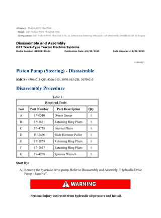
- 1. Product: TRACK-TYPE TRACTOR Model: D6T TRACK-TYPE TRACTOR SMC Configuration: D6T TRACK-TYPE TRACTOR STD, XL Differential Steering SMC00001-UP (MACHINE) POWERED BY C9 Engine Disassembly and Assembly D6T Track-Type Tractor Machine Systems Media Number -KENR5130-04 Publication Date -01/09/2015 Date Updated -15/09/2015 i01850521 Piston Pump (Steering) - Disassemble SMCS - 4306-015-QP; 4306-015; 5070-015-ZH; 5070-015 Disassembly Procedure Table 1 Required Tools Tool Part Number Part Description Qty A 1P-0510 Driver Group 1 B 1P-1861 Retaining Ring Pliers 1 C 5P-4758 Internal Pliers 1 D 1U-7600 Slide Hammer Puller 1 E 1P-1859 Retaining Ring Pliers 1 F 1P-1857 Retaining Ring Pliers 1 G 1S-4208 Spanner Wrench 1 Start By: A. Remove the hydraulic drive pump. Refer to Disassembly and Assembly, "Hydraulic Drive Pump - Remove". Personal injury can result from hydraulic oil pressure and hot oil. 1/23 D6T TRACK-TYPE TRACTOR STD, XL Differential Steering SMC00001-UP (MA... 2021/6/14 https://127.0.0.1/sisweb/sisweb/techdoc/techdoc_print_page.jsp?returnurl=/sis...
- 2. Hydraulic oil pressure can remain in the hydraulic system after the engine has been stopped. Serious injury can be caused if this pressure is not released before any service is done on the hydraulic system. Make sure all of the work tools have been lowered to the ground, and the oil is cool before removing any components or lines. Remove the oil filler cap only when the engine is stopped, and the filler cap is cool enough to touch with your bare hand. Note: Cleanliness is an important factor. Before the disassembly procedure, the exterior of the component should be thoroughly cleaned. This will help to prevent dirt from entering the internal mechanism. Dirt and contaminants can damage the components of the pump or the motor. All disassembly and assembly procedures must be performed on a clean work surface. Clean all the interior components in clean solvent. Dry all the interior components with compressed air. Plug ports and plug hoses on the machine during repair. NOTICE Care must be taken to ensure that fluids are contained during performance of inspection, maintenance, testing, adjusting and repair of the product. Be prepared to collect the fluid with suitable containers before opening any compartment or disassembling any component containing fluids. Refer to Special Publication, NENG2500, "Caterpillar Tools and Shop Products Guide" for tools and supplies suitable to collect and contain fluids on Caterpillar products. Dispose of all fluids according to local regulations and mandates. Illustration 1 g00775547 1. Remove bolts (1) and remove charge pump (2) . 2/23 D6T TRACK-TYPE TRACTOR STD, XL Differential Steering SMC00001-UP (MA... 2021/6/14 https://127.0.0.1/sisweb/sisweb/techdoc/techdoc_print_page.jsp?returnurl=/sis...
- 3. Illustration 2 g00716074 Note: Mark the location of the charge pump on the head assembly. Crescent (M) of gear set (4) must face toward the valves for installation purposes. The valves are indicated by arrows. 2. Remove O-ring seal (3). Remove gear set (4). Keep the gear set together in order to ensure proper installation of the gear set. Illustration 3 g00580966 3. Remove bushing (5). Note the orientation of the bushing. The bushing must be installed in the original location. 3/23 D6T TRACK-TYPE TRACTOR STD, XL Differential Steering SMC00001-UP (MA... 2021/6/14 https://127.0.0.1/sisweb/sisweb/techdoc/techdoc_print_page.jsp?returnurl=/sis...
- 4. Illustration 4 g00580969 4. Remove plate (6). Note the position of the plate. Illustration 5 g00580995 5. Remove shaft (7) and O-ring seal (8) . Illustration 6 g00581004 6. Remove snap ring (9) and key (10) from the shaft. 4/23 D6T TRACK-TYPE TRACTOR STD, XL Differential Steering SMC00001-UP (MA... 2021/6/14 https://127.0.0.1/sisweb/sisweb/techdoc/techdoc_print_page.jsp?returnurl=/sis...
- 5. Illustration 7 g00581009 7. Remove bolts (11) and head assembly (12) . Illustration 8 g00581016 8. Remove O-ring seals (13) and (14) from the head. 5/23 D6T TRACK-TYPE TRACTOR STD, XL Differential Steering SMC00001-UP (MA... 2021/6/14 https://127.0.0.1/sisweb/sisweb/techdoc/techdoc_print_page.jsp?returnurl=/sis...
- 6. Illustration 9 g00581023 Illustration 10 g00581022 9. Use Tooling (A) in order to remove bushing (15) . Illustration 11 g00581027 10. Remove bushing (16) . Note: Mark orientation of groove in bushing (16) for later installation of new bushing into the original location. 6/23 D6T TRACK-TYPE TRACTOR STD, XL Differential Steering SMC00001-UP (MA... 2021/6/14 https://127.0.0.1/sisweb/sisweb/techdoc/techdoc_print_page.jsp?returnurl=/sis...
- 7. Illustration 12 g00794209 Note: Mark the position of the port plate for installation purposes. The groove in the port plate must face the two valves on the head assembly. 11. Remove port plate (17) and bearing (18), if necessary. Note: Perform Steps 12 and 13, if equipped. Illustration 13 g00794067 12. Remove plug assembly (19) from the head. 7/23 D6T TRACK-TYPE TRACTOR STD, XL Differential Steering SMC00001-UP (MA... 2021/6/14 https://127.0.0.1/sisweb/sisweb/techdoc/techdoc_print_page.jsp?returnurl=/sis...
- 8. Illustration 14 g00794187 13. Disassemble the plug assembly, as follows: O-ring seal (20), O-ring seal (21) and locking plug (22) . Illustration 15 g00722813 14. Remove valve (23) from the head. 8/23 D6T TRACK-TYPE TRACTOR STD, XL Differential Steering SMC00001-UP (MA... 2021/6/14 https://127.0.0.1/sisweb/sisweb/techdoc/techdoc_print_page.jsp?returnurl=/sis...
- 9. Illustration 16 g00581200 15. Disassemble the valve, as follows: O-ring seal (26), backup ring (25) and O-ring seal (24) . Illustration 17 g00581207 16. Remove valve (27) from the head. Refer to Step 15 for the disassembly procedure. Illustration 18 g00581224 17. Remove bolts (28) and cover assembly (29) . 9/23 D6T TRACK-TYPE TRACTOR STD, XL Differential Steering SMC00001-UP (MA... 2021/6/14 https://127.0.0.1/sisweb/sisweb/techdoc/techdoc_print_page.jsp?returnurl=/sis...
- 10. 18. Repeat Step 17 for the opposite side. Illustration 19 g00581225 19. Remove O-ring seal (30) and valve (31) . Illustration 20 g00581264 20. Remove bolts (32) and cover (33) . 10/23 D6T TRACK-TYPE TRACTOR STD, XL Differential Steering SMC00001-UP (M... 2021/6/14 https://127.0.0.1/sisweb/sisweb/techdoc/techdoc_print_page.jsp?returnurl=/sis...
- 11. Illustration 21 g00581276 21. Remove gasket (35), bolts (34), and valve assembly (36) . Illustration 22 g00581281 22. Remove O-ring seals (37) . Illustration 23 g00581282 23. Remove O-ring seals (38), (39), and (40) . 11/23 D6T TRACK-TYPE TRACTOR STD, XL Differential Steering SMC00001-UP (M... 2021/6/14 https://127.0.0.1/sisweb/sisweb/techdoc/techdoc_print_page.jsp?returnurl=/sis...
- 12. Illustration 24 g00581734 24. Remove barrel assembly (41) from the pump housing. Keep the barrel assembly together with the pistons. Illustration 25 g00581740 25. Mark the location of the pistons in the barrel assembly. Remove pistons and plate (42) from the barrel assembly. Illustration 26 g00581773 12/23 D6T TRACK-TYPE TRACTOR STD, XL Differential Steering SMC00001-UP (M... 2021/6/14 https://127.0.0.1/sisweb/sisweb/techdoc/techdoc_print_page.jsp?returnurl=/sis...
- 13. 26. Remove spring retainer (43) . Illustration 27 g00581780 Personal injury can result from being struck by parts propelled by a released spring force. Make sure to wear all necessary protective equipment. Follow the recommended procedure and use all recommended tooling to release the spring force. 27. Remove shim (44) and springs (45). Note the position of the springs. The springs must be installed in the same position for proper clearance. Illustration 28 g00581784 13/23 D6T TRACK-TYPE TRACTOR STD, XL Differential Steering SMC00001-UP (M... 2021/6/14 https://127.0.0.1/sisweb/sisweb/techdoc/techdoc_print_page.jsp?returnurl=/sis...
- 14. 28. Use Tooling (B) in order to remove retaining ring (46) . Illustration 29 g00581786 Personal injury can result from being struck by parts propelled by a released spring force. Make sure to wear all necessary protective equipment. Follow the recommended procedure and use all recommended tooling to release the spring force. 29. Remove washer (47), spring (48), and washer (47) from the barrel assembly. Illustration 30 g00581792 30. Use Tooling (C) in order to remove retaining ring (49) . 14/23 D6T TRACK-TYPE TRACTOR STD, XL Differential Steering SMC00001-UP (M... 2021/6/14 https://127.0.0.1/sisweb/sisweb/techdoc/techdoc_print_page.jsp?returnurl=/sis...
- 15. Illustration 31 g00581821 31. Use Tooling (D) in order to remove seal (50) . Illustration 32 g00581830 32. Use Tooling (C) in order to remove retaining ring (51) . 15/23 D6T TRACK-TYPE TRACTOR STD, XL Differential Steering SMC00001-UP (M... 2021/6/14 https://127.0.0.1/sisweb/sisweb/techdoc/techdoc_print_page.jsp?returnurl=/sis...
- 16. Illustration 33 g00581848 Illustration 34 g00581850 33. Remove shaft (52). It may be necessary to use a soft faced hammer in order to remove the shaft. Illustration 35 g00581928 34. Use Tooling (E) in order to remove retaining ring (53) . 16/23 D6T TRACK-TYPE TRACTOR STD, XL Differential Steering SMC00001-UP (M... 2021/6/14 https://127.0.0.1/sisweb/sisweb/techdoc/techdoc_print_page.jsp?returnurl=/sis...
- 17. Illustration 36 g00581934 35. Use a suitable press in order to remove shaft (52) from bearing (54) . Illustration 37 g00581942 36. Remove swashplate assembly (55) . Illustration 38 g00581947 37. Remove plate (56) from the swashplate. Remove rods (57) from the swashplate. 17/23 D6T TRACK-TYPE TRACTOR STD, XL Differential Steering SMC00001-UP (M... 2021/6/14 https://127.0.0.1/sisweb/sisweb/techdoc/techdoc_print_page.jsp?returnurl=/sis...
- 18. Illustration 39 g00582435 38. Remove bearings (58) . Illustration 40 g00582451 39. Remove bearing cradles (59) . Illustration 41 g00720021 40. Remove plug (61) and retainer (60) on both sides of the pump housing. 18/23 D6T TRACK-TYPE TRACTOR STD, XL Differential Steering SMC00001-UP (M... 2021/6/14 https://127.0.0.1/sisweb/sisweb/techdoc/techdoc_print_page.jsp?returnurl=/sis...
- 19. Illustration 42 g00582463 Illustration 43 g00582491 41. Remove bolts (62). Remove cover (63) with valve assembly (64) . Illustration 44 g00582495 42. Remove bolts (65) and cover (66) . 19/23 D6T TRACK-TYPE TRACTOR STD, XL Differential Steering SMC00001-UP (M... 2021/6/14 https://127.0.0.1/sisweb/sisweb/techdoc/techdoc_print_page.jsp?returnurl=/sis...
- 20. Illustration 45 g00582504 43. Remove O-ring seal (67) from the cover. Illustration 46 g00794220 44. Remove nut (68). Unscrew the cover from the valve assembly. 20/23 D6T TRACK-TYPE TRACTOR STD, XL Differential Steering SMC00001-UP (M... 2021/6/14 https://127.0.0.1/sisweb/sisweb/techdoc/techdoc_print_page.jsp?returnurl=/sis...
- 21. Illustration 47 g00794221 45. Remove O-ring seal (69) . Illustration 48 g00794223 Ring (71) is on the opposite end. 46. Remove O-ring seal (72), and rings (70) and (71) from each side. Personal injury can result from parts and/or covers under spring pressure. Spring force will be released when covers are removed. Be prepared to hold spring loaded covers as the bolts are loosened. 21/23 D6T TRACK-TYPE TRACTOR STD, XL Differential Steering SMC00001-UP (M... 2021/6/14 https://127.0.0.1/sisweb/sisweb/techdoc/techdoc_print_page.jsp?returnurl=/sis...
- 22. Illustration 49 g00582619 47. Use a suitable press to relieve the pressure on the spring. Use Tooling (F) in order to remove retaining ring (73) . Illustration 50 g00582622 48. Use a suitable press and Tooling (G) to relieve the pressure on the spring. Remove spacer (74). Slowly release the pressure on the spring. Illustration 51 g00582628 49. Remove retainer (75) . 22/23 D6T TRACK-TYPE TRACTOR STD, XL Differential Steering SMC00001-UP (M... 2021/6/14 https://127.0.0.1/sisweb/sisweb/techdoc/techdoc_print_page.jsp?returnurl=/sis...
- 23. Illustration 52 g00582652 Personal injury can result from being struck by parts propelled by a released spring force. Make sure to wear all necessary protective equipment. Follow the recommended procedure and use all recommended tooling to release the spring force. 50. Remove springs (76) and (77). Illustration 53 g00582656 51. Remove retainer (78). Repeat Steps 47 through 51 for the opposite side of the valve. 23/23 D6T TRACK-TYPE TRACTOR STD, XL Differential Steering SMC00001-UP (M... 2021/6/14 https://127.0.0.1/sisweb/sisweb/techdoc/techdoc_print_page.jsp?returnurl=/sis...
- 24. Product: TRACK-TYPE TRACTOR Model: D6T TRACK-TYPE TRACTOR SMC Configuration: D6T TRACK-TYPE TRACTOR STD, XL Differential Steering SMC00001-UP (MACHINE) POWERED BY C9 Engine Disassembly and Assembly D6T Track-Type Tractor Machine Systems Media Number -KENR5130-04 Publication Date -01/09/2015 Date Updated -15/09/2015 i02583397 Piston Pump (Steering) - Assemble SMCS - 4306-016-QP; 4306-016; 5070-016-ZH; 5070-016 Assembly Procedure Table 1 Required Tools Tool Part Number Part Description Qty A 1S-4208 Spanner Wrench 1 B 1P-1857 Retaining Ring Pliers 1 C 1P-0510 Driver Group 1 D 1P-1859 Retaining Ring Pliers 1 E 1P-1861 Retaining Ring Pliers 1 F 135-8292 Alignment Plug 1 G 135-8296 Test Ring 1 H 128-2744 Measuring Bell 1 I 135-8294 Measuring Hub 1 J 5P-4758 Internal Pliers 1 K 4C-6142 Spacer 1 L 9U-5719 heat Shrink Tubing 1 1/26 D6T TRACK-TYPE TRACTOR STD, XL Differential Steering SMC00001-UP (MA... 2021/6/14 https://127.0.0.1/sisweb/sisweb/techdoc/techdoc_print_page.jsp?returnurl=/sis...
- 25. Personal injury can result from hydraulic oil pressure and hot oil. Hydraulic oil pressure can remain in the hydraulic system after the engine has been stopped. Serious injury can be caused if this pressure is not released before any service is done on the hydraulic system. Make sure all of the work tools have been lowered to the ground, and the oil is cool before removing any components or lines. Remove the oil filler cap only when the engine is stopped, and the filler cap is cool enough to touch with your bare hand. NOTICE Care must be taken to ensure that fluids are contained during performance of inspection, maintenance, testing, adjusting and repair of the product. Be prepared to collect the fluid with suitable containers before opening any compartment or disassembling any component containing fluids. Refer to Special Publication, NENG2500, "Caterpillar Dealer Service Tool Catalog" for tools and supplies suitable to collect and contain fluids on Caterpillar products. Dispose of all fluids according to local regulations and mandates. Note: Cleanliness is an important factor. Before assembly, all parts should be thoroughly cleaned in cleaning fluid. Allow the parts to air dry. Wiping cloths or rags should not be used to dry parts. Lint may be deposited on the parts which may cause later trouble. Inspect all parts. If any parts are worn or damaged, use new parts for replacement. Dirt and other contaminants can damage the precision components of the pump or of the motor. All disassembly and all assembly procedures must be performed on a clean work surface and in a clean hydraulic area. Keep cleaned parts covered and protected at all times. 2/26 D6T TRACK-TYPE TRACTOR STD, XL Differential Steering SMC00001-UP (MA... 2021/6/14 https://127.0.0.1/sisweb/sisweb/techdoc/techdoc_print_page.jsp?returnurl=/sis...
- 26. Illustration 1 g00582656 1. Install retainer (78) . Illustration 2 g00582652 Improper assembly of parts that are spring loaded can cause bodily injury. To prevent possible injury, follow the established assembly procedure and wear protective equipment. 2. Install springs (77) and (76) . Illustration 3 g00582628 3. Install retainer (75) . 3/26 D6T TRACK-TYPE TRACTOR STD, XL Differential Steering SMC00001-UP (MA... 2021/6/14 https://127.0.0.1/sisweb/sisweb/techdoc/techdoc_print_page.jsp?returnurl=/sis...
- 27. Improper assembly of parts that are spring loaded can cause bodily injury. To prevent possible injury, follow the established assembly procedure and wear protective equipment. Illustration 4 g00583692 4. Use a suitable press and Tooling (A) to relieve the pressure on the spring. Install spacer (74) . Slowly release the pressure on the spring. Illustration 5 g00583696 5. Use a suitable press to relieve the pressure on the spring. Use Tooling (B) in order to install retaining ring (73) . Repeat Steps 1 through 5 for the other side of the valve. 4/26 D6T TRACK-TYPE TRACTOR STD, XL Differential Steering SMC00001-UP (MA... 2021/6/14 https://127.0.0.1/sisweb/sisweb/techdoc/techdoc_print_page.jsp?returnurl=/sis...
- 28. Illustration 6 g00794223 6. Install rings (70) and (71) on each side. Install O-ring seal (72) . Illustration 7 g00794221 7. Install O-ring seal (69) . Illustration 8 g00794220 8. Screw the cover onto the valve. Install nut (68) . 5/26 D6T TRACK-TYPE TRACTOR STD, XL Differential Steering SMC00001-UP (MA... 2021/6/14 https://127.0.0.1/sisweb/sisweb/techdoc/techdoc_print_page.jsp?returnurl=/sis...
- 29. Suggest: If the above button click is invalid. Please download this document first, and then click the above link to download the complete manual. Thank you so much for reading
- 30. Illustration 9 g00582504 9. Install O-ring seal (67) on the cover. Illustration 10 g00582495 10. Install cover (66) and bolts (65) . 6/26 D6T TRACK-TYPE TRACTOR STD, XL Differential Steering SMC00001-UP (MA... 2021/6/14 https://127.0.0.1/sisweb/sisweb/techdoc/techdoc_print_page.jsp?returnurl=/sis...
- 31. Illustration 11 g00582491 Illustration 12 g00582463 11. Install cover (63) with valve assembly (64) . Install bolts (62) . Illustration 13 g00582451 12. Install bearing cradles (59) . Install retainers (60) . Note: The following components must be assembled in a vertical position: bearing cradles, swashplate assembly, shaft assembly and barrel assembly. 7/26 D6T TRACK-TYPE TRACTOR STD, XL Differential Steering SMC00001-UP (MA... 2021/6/14 https://127.0.0.1/sisweb/sisweb/techdoc/techdoc_print_page.jsp?returnurl=/sis...