Modeling and analysis of naca 66 206 aerofoil propeller

Abstract NACA aerofoil shapes have been successfully used over the years as wing and tail sections for general aviation and military aircraft, as well as propellers and helicopter rotors. The aircraft performance is highly affected by induced drag caused by wingtip vortices to improve fuel efficiency. In this research work, the analysis of NACA 66-206 aerofoil propellers was investigated for high-speed aircraft propulsion.CFD analysis is performed on the NACA aerofoil to verify the aerodynamic characteristics and enhancing the lift of the aircraft by changing the orientation of angle of attack 00, 100 and 200 and to determine the drag and lift coefficients by applying inlet velocities. An auxiliary part, winglets are added on propeller blade tip in order to improve the performance of propeller. By adding this auxiliary equipment the weight of propeller are significantly increased. To decrease the weight without compromising the performance of the propeller the fiber reinforced composite materials are used. The effects of stacking sequence layers of composite materials, which were fabricated from Kevlar, carbon, glass fibres, and epoxy resin have been used to increase the strength to weight ratio. To validate the strength of the propeller, Structural and buckling analysis is performed. Keywords: Aerofoil, Propeller, fiber reinforcement and strength etc…

Recommended
Recommended
More Related Content
What's hot
What's hot (19)
Similar to Modeling and analysis of naca 66 206 aerofoil propeller
Similar to Modeling and analysis of naca 66 206 aerofoil propeller (20)
More from eSAT Journals
More from eSAT Journals (20)
Recently uploaded
Recently uploaded (20)
Modeling and analysis of naca 66 206 aerofoil propeller
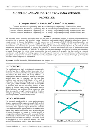
- 1. IJRET: International Journal of Research in Engineering and Technology eISSN: 2319-1163 | pISSN: 2321-7308 _______________________________________________________________________________________ Volume: 04 Issue: 01 | Jan-2015, Available @ http://www.ijret.org 391 MODELING AND ANALYSIS OF NACA 66-206 AEROFOIL PROPELLER S. Ganapathi Alapati1 , A. Srinivasa Rao2 , M.Ramji3 , P.S.B.Choudary4 1 Student, Mechanical Engineering, Sir.C.R.Reddy College of Engineering, AndhraPradesh, India 2 Assistant Professor, Mechanical Engineering, Sir.C.R.Reddy College of Engineering, AndhraPradesh, India 3 Associate Professor, Mechanical Engineering, Sir.C.R.Reddy College of Engineering, AndhraPradesh, India 4 Associate Professor, Mechanical Engineering, Sir.C.R.Reddy College of Engineering, AndhraPradesh, India Abstract NACA aerofoil shapes have been successfully used over the years as wing and tail sections for general aviation and military aircraft, as well as propellers and helicopter rotors. The aircraft performance is highly affected by induced drag caused by wingtip vortices to improve fuel efficiency. In this research work, the analysis of NACA 66-206 aerofoil propellers was investigated for high-speed aircraft propulsion.CFD analysis is performed on the NACA aerofoil to verify the aerodynamic characteristics and enhancing the lift of the aircraft by changing the orientation of angle of attack 00 , 100 and 200 and to determine the drag and lift coefficients by applying inlet velocities. An auxiliary part, winglets are added on propeller blade tip in order to improve the performance of propeller. By adding this auxiliary equipment the weight of propeller are significantly increased. To decrease the weight without compromising the performance of the propeller the fiber reinforced composite materials are used. The effects of stacking sequence layers of composite materials, which were fabricated from Kevlar, carbon, glass fibres, and epoxy resin have been used to increase the strength to weight ratio. To validate the strength of the propeller, Structural and buckling analysis is performed. Keywords: Aerofoil, Propeller, fiber reinforcement and strength etc… --------------------------------------------------------------------***---------------------------------------------------------------------- 1. INTRODUCTION The work based on the study of aerodynamic characteristics of aerofoil and also by adding auxiliary component to it to increase the performance. For the study of aerodynamics the flow analysis has been carried out at high altitudes .The work continues with the modeling of propeller by the above aerofoil shape and its structural and buckling load conditions were analyzed. Final objective of my work to enhance the lift and reduction of drag forces of the aircraft. Carbon, glass, and Kevlar fibre composites are susceptible to accidental from low to high-energy impacts of such hazards as dropped tools during maintenance, runway debris, hail-stones and sandstorm. These impacts can bring about considerable strength reduction, and the localized damage is potentially a source of mechanical weakness, particularly under the mechanical applications 1.1 NACA 66-206 Aerofoil The supersonic speed aerofoil is a cross section geometry designed to generate lift at supersonic speeds. Such aerofoils are explicitly designed for aircrafts that need to operate consistently in the supersonic regime. Supersonic aerofoil is a thin section of either angled planes or of opposed arcs, having sharp leading and trailing edges so as to prevent formation of detached bow shock. In a typical aerofoil, at some point along the aerofoil, a shock is generated when the local velocity of flow reaches Mach 1 which increases the pressure coefficient to the critical value. The aerofoil chosen for this analysis is a NACA 66-206 aerofoil, a 6% thick aerofoil. Maintaining the Integrity of the Specifications Fig.1.1.Propeller Model without winglet Fig.1.2.Propeller Model with winglet
- 2. IJRET: International Journal of Research in Engineering and Technology eISSN: 2319-1163 | pISSN: 2321-7308 _______________________________________________________________________________________ Volume: 04 Issue: 01 | Jan-2015, Available @ http://www.ijret.org 392 1.2 Need of CFD Analysis on aerofoil propeller Computational fluid dynamics (CFD) is the science of predicting fluid flow, heat transfer, mass transfer, chemical reactions, and related phenomena by solving the mathematical equations which govern these processes using a numerical process. 2. BOUNDARY CONDITIONS Table.2.1. Boundary conditions and flow parameters Sl.No. Input Value 1 Velocity of flow 2.5 Mach or 156.5 m/s 2 Operating temperature 300 K 3 Operating pressure 101325 Pa 5 Density of fluid 1.29 Kg/m3 6 Kinematic viscosity 1.4607 × 10⁻⁵ Fig. 2.1.At 100 angle of attack Fig.2.2.At 200 angle of attack
- 3. IJRET: International Journal of Research in Engineering and Technology eISSN: 2319-1163 | pISSN: 2321-7308 _______________________________________________________________________________________ Volume: 04 Issue: 01 | Jan-2015, Available @ http://www.ijret.org 393 Table.2.2. Coefficient of lift and Coefficient of drag for Propeller without winglet model Angle of attack Coefficient of lift Coefficient of drag CL/CD 00 2.38E-05 1.76E-04 0.1349 100 1.09E-04 8.10E-04 0.1345 200 1.92E-04 7.58E-04 0.2536 Fig.2.3. C/CD at 00 , 100 , 200 Angle of attack Table.2.3. Structural analysis result of Propeller with winglets model Al alloy 7475 Kevlar Fiber/ Epoxy composite S2Glass Fiber/ Epoxy composite Carbon Fiber/ Epoxy composite Displacement (mm) 0.20154 0.59213 0.12416 0.40538 Stress (N/mm2 ) 413.641 580.728 575.784 590.681 Strain 0.002527 0.010738 0.003944 0.004055 Table.2.4. Structural analysis result of Propeller without winglets model Al alloy 7475 Kevlar Fiber/ Epoxy composite S2Glass Fiber/ Epoxy composite Carbon Fiber/ Epoxy composite Displacement(m m) 0.2984 0.6082 0.319482 0.8098 Stress(N/mm2 ) 402.38 579.913 524.861 583.694 Strain 0.001927 0.010688 0.002056 0.00804 0 0.1 0.2 0.3 0.4 0.5 0.6 0.7 0.8 0.9 1 0 degree 10 degree 20 degree CL /CD Angle of attack Propeller without winglet Propeller with winglet
- 4. IJRET: International Journal of Research in Engineering and Technology eISSN: 2319-1163 | pISSN: 2321-7308 _______________________________________________________________________________________ Volume: 04 Issue: 01 | Jan-2015, Available @ http://www.ijret.org 394 Fig.2.4. Stress results for propeller models Table.2.5. Buckling analysis result for propeller without winglet model Al Alloy 7475 Kevlar Fiber/ Epoxy composite S2Glass Fiber/ Epoxy composite Carbon Fiber/Epoxy composite Buckling Factor 1 1.701 1.55718 2.04532 6.84965 Buckling Factor 2 1.598 1.04078 2.19307 7.34385 Table.2.6. Buckling analysis result for propeller with winglet model Al Alloy 7475 Kevlar Fiber/ Epoxy composite S2Glass Fiber/ Epoxy composite Carbon Fiber/Epoxy composite Buckling Factor 1 1.675 1.07031 2.07189 2.98935 Buckling Factor 2 1.899 1.0929 2.08935 3.97189 Fig.2.5. Buckling Factor 1 for propeller models 0 500 1000 1500 2000 2500 Propeller without Winglets Propeller with Winglets Stress(N/mm2) Propeller Models Carbon fiber/Epoxy S2Glass/Epoxy Kevlar/Epoxy Aluminum alloy 7475 0 2 4 6 8 10 12 14 Propeller without Winglets Propeller with Winglets BucklingFactor1 Propeller Models Carbon fiber/Epoxy S2Glass/Epoxy Kevlar/Epoxy Aluminum alloy 7475
- 5. IJRET: International Journal of Research in Engineering and Technology eISSN: 2319-1163 | pISSN: 2321-7308 _______________________________________________________________________________________ Volume: 04 Issue: 01 | Jan-2015, Available @ http://www.ijret.org 395 Fig.2.6. Buckling Factor 2 for propeller models 3. CONCLUSION After successfully completing this simulation based experiment, the decisions were finally confined into the following points. From CFD analysis Coefficient of drag and coefficient of lift were found for different angle of attack from the simulation. Finally, lift to drag ratio for these aerofoil were compared to find out the better model. In this case, propeller with winglet model is better than propeller without winglet model. In this study, both aerodynamic and structural design of the propeller blade for an advanced turboprop aircraft is performed using layer stacking method. The propeller blade airfoil is an important factor to determine a good propeller performance. In structural design, the carbon/epoxy composite structure is used to endure effectively under various loads. The carbon fiber reinforced composite propeller gives high buckling factors because of its material nature and when model taken in to consideration the propeller without winglets gives better result. It was shown that design can significantly increase buckling resistance capability of composite material structures. REFERENCES [1] Aerodynamic Analysis of Variable Cant Angle Winglets for Improved Aircraft Performance by A. Beechook, J. Wang, Assistant Lecturer in Aerospace Engineering at Coventry University, The 19th International Conference on Automation and Computing (ICAC’13). [2] Aircraft drag reduction—a review by D M Bushnell NASA Langley Research Center, Mail Stop 110, Hampton, Virginia 23681±0001, USA, IMechE 2003 [3] Taylor D.W, “The speed and power and ships” Washington, 1933. [4] J.E.Conolly “Strength of Propellers” reads in London at a meeting of the royal intuition of naval architects on dec 1, 1960, pp 139-160. [5] Elias Randjbaran*, Rizal Zahari, Dayang Laila Majid, Nawal Aswan Abdul Jalil, Ramin Vaghei and Ramin Ahmadi. ‘‘The Effects of Stacking Sequence Layers of Hybrid Composite Materials in Energy Absorption under the High Velocity Ballistic Impact Conditions”: An Experimental Investigation, Faculty of Engineering, Universiti Putra Malaysia, 43400 UPM Serdang, Selangor Darul Ehsan, Malaysia [6] H. Ghasemnejad and A. Maheri “Delamination buckling analysis for design of horizontal axis wind turbine (HAWT) composite blades ‘’Faculty of Engineering, Kingston University London, SW15 3DW, UK. [7] Bousquet J. M. “Theoretical and experimental analysis of highspeed propeller aerodynamics”. Proceeding in AIAA/ASME/SAE/ASEE 22nd Joint Propulsion Conference, 1986.. [8] Cambier L. and Gazaix M. “elsA: an efficient object-oriented solution to CFD complexity” Proceeding in 40th AIAA Aerospace Science Meeting and Exhibit, 2002. 0 2 4 6 8 10 12 14 Propeller without Winglets Propeller with Winglets BucklingFactor2 Propeller Models Carbon fiber/Epoxy S2Glass/Epoxy Kevlar/Epoxy Aluminum alloy 7475
- 6. IJRET: International Journal of Research in Engineering and Technology eISSN: 2319-1163 | pISSN: 2321-7308 _______________________________________________________________________________________ Volume: 04 Issue: 01 | Jan-2015, Available @ http://www.ijret.org 396 BIOGRAPHIES S. Ganapathi Alapati, Master of Engineering in Machine Design, Mechanical Engineering, Sir.C.R.Reddy College of Engineering, AndhraPradesh, India A. Srinivasa Rao, Assistant Professor, Mechanical Engineering, Sir.C.R.Reddy College of Engineering, AndhraPradesh, India M.Ramji, Associate Professor, Mechanical Engineering, Sir.C.R.Reddy College of Engineering, AndhraPradesh, India P.S.B.Choudary, Associate Professor, Mechanical Engineering, Sir.C.R.Reddy College of Engineering, AndhraPradesh, India