
Recommended
More Related Content
Similar to Fk245 te 3-a3
Similar to Fk245 te 3-a3 (20)
Recently uploaded
Recently uploaded (20)
Fk245 te 3-a3
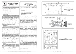
- 1. LEVEL1CODE 245 http://www.futurekit.com FUTURE KIT FUTURE KIT HIGH QUALITY ELECTRONIC KITS HIGH QUALITY ELECTRONIC KIT SET FOR HOBBY & EDUCATION R ǧ¨Ã»ÅØ¡´éÇÂáʧµÐÇѹ LIGHT ACTIVATE ALARM Figure 1. The Light Activate Alarm Circuit NOTE: FUTURE BOX FB03 is suitable for this kit. SP +9V G 9V 43 21 VR1 +++ + LED K A PHOTO FK245 SPEAKER 8 Ω 0.25W POWER SOURCE 9V Figure 3. Installing the components RESISTOR CERAMIC CAPACITOR ELECTROLYTIC CAPACITOR Watch the polarity! TRANSISTOR LED DIODE TRIMMER POTENTIOMETER HORIZONTAL VERTICAL R .....Ω R R C C .....µF C C + + C .....µF C + TR NPN B E C TR PNP B E C K A KA LED LED L E D K A D K A D K A VR .....KΩ 1 2 3 VR VR VR VR It is the circuit that alarms when the light shines on its phottransistor. Technical data - Power supply : 12VDC. - Electric current consumption : 22mA (max.) - IC board dimension : 2.38 in x 1.24 in How does it work The phototransistor generator voltage when the light shines on it and disables TR1 and TR2, and causes TR3 and TR4 which form a frequency generating circuit disable but actuates TR1 and TR2 instead. Onc TR2 starts working its leg C has high current, so leg B of TR3 gains voltage through R5 and finally TR3 and TR4 generate the frequency by alarming via the loudspeaker and the LED simultaneously turns on. Circuit Assembly The assembly of components is shown in Fig. 2. For good looking and easy assembly, the shorter components should be first installed - starting with low resistant components and then the higher. An important thing is that diodes, electrolyte capacitors, and transistors shall be carefully assembled before mounting them onto their right anode/cathode of the IC board otherwise it might cause damage to the components or the circuit. Configuration of the anode and the cathode is shown in Fig 3. Use the soldering iron/gun not exceeding 40 watts and the solder of tin-lead 60:40 with flux within. Recheck the correctness of installation after soldering. In case of wrong position, just use lead absorber or lead extractor wire to avoid probable damage to the IC. Testing Energive 9VDC to the circuit and connect the anode to point +9V, the cathode to point G. Connect the loudspeaker at point SP. Turn the phototransistor to the light, LED will turn on and simultaneously alarms the loudspeaker. Test the circuit by palm covering the phototransistor, LED will turn off and simultaneously silences the loudspeaker. The VR1 is provided for adjustment of light sensitivity. ǧ¨Ã»ÅØ¡´éÇÂáʧ ¡ç¤×Í Ç§¨Ã·ÕèÁÕàÊÕ§àµ×͹àÁ×èÍÁÕáʧÁÒ¡Ãзº ǧ¨Ã â´Âǧ¨Ã¨ÐÁÕµÑÇÃѺáʧ·ÕèàÃÕ¡ÇèÒ â¿âµé·ÃÒ¹«ÔÊàµÍÃì ¢éÍÁÙÅ·Ò§´éҹ෤¹Ô¤ - ãªéáËÅ觨èÒÂä¿¢¹Ò´ 9 âÇÅ·ì´Õ«Õ - ¡Ô¹¡ÃÐáÊÊÙ§ÊØ´»ÃÐÁÒ³ 22 ÁÔÅÅÔáÍÁ»ì - ¢¹Ò´á¼è¹Ç§¨Ã¾ÔÁ¾ì : 2.38 x 1.24 ¹ÔéÇ ¡Ò÷ӧҹ¢Í§Ç§¨Ã â¿âµé·ÃÒ¹«ÔÊàµÍÃì¨Ð·Ó˹éÒ·ÕèÃѺáʧàÁ×èÍÁÕáʧÁÒµ¡¡Ãзº ¨Ð·ÓãËéâ¿âµé·ÃÒ¹«ÔÊàµÍ÷ӧҹáÅÐÁÕáç´Ñ¹äËżèÒ¹µÑÇÁѹ áµè àÁ×èÍäÁèÁÕáʧÁÒµ¡¡Ãзºâ¿âµé·ÃÒ¹«ÔÊàµÍÃì ¨Ð·ÓãËéäÁèÁÕáç´Ñ¹ äËżèÒ¹µÑÇÁѹ ´Ñ§¹Ñ鹨֧·ÓãËé TR1, TR2 äÁèÊÒÁÒö·Ó§Ò¹ä´é TR3, TR4 «Ö觵èÍà»ç¹Ç§¨Ã¡Óà¹Ô´¤ÇÒÁ¶Õè¡ç¨ÐäÁè·Ó§Ò¹ àÁ×èÍÁÕáʧÁÒ ¡Ãзº â¿âµé·ÃÒ¹«ÔÊàµÍÃì¨Ð·ÓãËéÁÕáç´Ñ¹äËżèÒ¹µÑÇÁѹ¨Ö§·Ó ãËé TR1, TR2 ·Ó§Ò¹ àÁ×èÍ TR2 ·Ó§Ò¹ ·Õè¢Ò C ¢Í§ TR2 ¨Ö§ÁÕä¿ÊÙ§ ´Ñ§¹Ñé¹·Õè¢Ò B ¢Í§ TR3 ¨Ö§ä´éÃѺáç俼èÒ¹ R5 ´Ñ§¹Ñé¹ TR3, TR4 ¨Ö§¡Óà¹Ô´ ¤ÇÒÁ¶Õè ÅÓ⾧¡ç¨ÐÊè§àÊÕ§àµ×͹¾ÃéÍÁæ ¡Ñº LED ¨ÐµÔ´ ¡ÒûÃСͺǧ¨Ã ÃÙ»¡ÒÃŧÍØ»¡Ã³ìáÅСÒõèÍÍØ»¡Ã³ìÀÒ¹͡áÊ´§äÇéã¹ÃÙ»·Õè 2 ã¹ ¡ÒûÃСͺǧ¨Ã¤ÇèÐàÃÔèÁ¨Ò¡ÍØ»¡Ã³ì·ÕèÁÕ¤ÇÒÁÊÙ§·Õè¹éÍ·ÕèÊØ´¡è͹ à¾×èͤÇÒÁÊǧÒÁáÅСÒûÃСͺ·Õè§èÒ â´ÂãËéàÃÔèÁ¨Ò¡ä´âÍ´µÒÁ ´éÇ µÑǵéÒ¹·Ò¹áÅÐäÅè¤ÇÒÁÊÙ§ä»àÃ×èÍÂæ ÊÓËÃѺÍØ»¡Ã³ì·ÕèÁÕ¢ÑéǵèÒ§æ àªè¹ ä´âÍ´, ¤Ò»Ò«ÔÊàµÍÃìẺÍÔàÅç¡·ÃÍäŵìáÅзÃÒ¹«ÔÊàµÍÃì à»ç¹ µé¹ ¤ÇÃãªé¤ÇÒÁÃÐÁÑ´ÃÐÇѧ㹡ÒûÃСͺǧ¨Ã ¡è͹¡ÒÃãÊèÍØ»¡Ã³ì àËÅèÒ¹Õé ¨ÐµéͧãËé¢ÑéÇ·Õèá¼è¹Ç§¨Ã¾ÔÁ¾ì¡ÑºµÑÇÍØ»¡Ã³ìãËéµÃ§¡Ñ¹ à¾ÃÒÐ ¶éÒËÒ¡ãÊè¡ÅѺ¢ÑéÇáÅéÇ ÍÒ¨¨Ð·ÓãËéÍØ»¡Ã³ìËÃ×Íǧ¨ÃàÊÕÂËÒÂä´é ÇÔ¸Õ¡Òà ´Ù¢ÑéÇáÅСÒÃãÊèÍØ»¡Ã³ì¹Ñé¹ä´éáÊ´§äÇéã¹ÃÙ»·Õè 3 áÅéÇ ã¹¡ÒúѴ¡ÃÕãËéãªé ËÑÇáÃ駢¹Ò´äÁèà¡Ô¹ 40 Çѵµì áÅÐãªéµÐ¡ÑèǺѴ¡ÃÕ·ÕèÁÕÍѵÃÒÊèǹ¢Í§´ÕºØ¡ áÅеСÑèÇÍÂÙèÃÐËÇèÒ§ 60/40 ÃÇÁ·Ñ駨еéͧÁÕ¹ÓéÂÒ»ÃÐÊÒ¹ÍÂÙèÀÒÂã¹ µÐ¡ÑèÇ´éÇ ËÅѧ¨Ò¡·Õèä´éãÊèÍØ»¡Ã³ìáÅкѴ¡ÃÕàÃÕºÃéÍÂáÅéÇ ãËé·Ó¡Òà µÃǨÊͺ¤ÇÒÁ¶Ù¡µéͧÍÕ¡¤ÃÑé§Ë¹Öè§ à¾×èÍãËéà¡Ô´¤ÇÒÁÁÑè¹ã¨á¡èµÑÇàÃÒàͧ áµè¶éÒà¡Ô´ãÊèÍØ»¡Ã³ì¼Ô´µÓáË¹è§ ¤ÇÃãªé·Õè´Ù´µÐ¡ÑèÇËÃ×ÍÅÇ´«ÑºµÐ¡ÑèÇ à¾×èÍ»éͧ¡Ñ¹¤ÇÒÁàÊÕÂËÒ·ÕèÍÒ¨¨Ðà¡Ô´¡ÑºÅÒÂǧ¨Ã¾ÔÁ¾ìä´é ¡Ò÷´Êͺ ¨èÒÂä¿à¢éÒǧ¨Ã â´Â¢ÑéǺǡµèÍ·Õè +9V ¢ÑéÇźµèÍ·Õè G µèÍÅÓ⾧ ·Õè ¨Ø´ SP Ëѹâ¿âµé·ÃÒ¹«ÔÊàµÍÃìà¢éÒËÒáʧ 㹵͹¹Õé LED ¨ÐµÔ´ ¾ÃéÍÁæ ¡ÑºÁÕàÊÕ§ÍÍ¡·Ò§ÅÓ⾧ ãËéàÍÒÁ×ͺѧâ¿âµé·ÃÒ¹«ÔÊàµÍÃìäÇé äÁèãËéâ´¹áʧ µÍ¹¹Õé LED ¨Ð´Ñº ¾ÃéÍÁæ ¡ÑºàÊÕ§·Õè´Ñ§ã¹µÍ¹áá¨Ð ËÂØ´ä» ÊÓËÃѺ VR1 ÁÕäÇéÊÓËÃѺ»ÃѺ¤ÇÒÁäÇ㹡ÒÃÃѺáʧ NO.3 Figure 2. Circuit Assembling