Stanley A Meyer Summary of tests of increase offset input to primary
•
0 likes•138 views

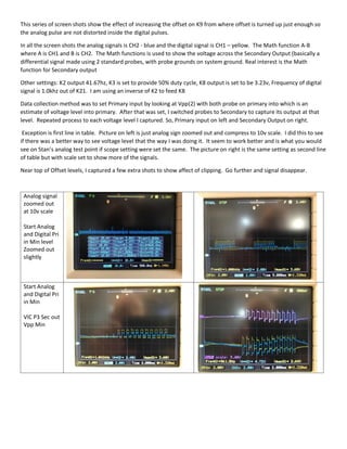
This document shows screen shots of increasing the offset on K9 to see the effect on analog and digital signals without distortion. The screen shots compare the analog signal on CH2 (blue) and digital signal on CH1 (yellow) with the math function of A-B to show the secondary output voltage. Settings included a K2 output of 41.67hz, K3 at 50% duty cycle, K8 output of 3.23v, and digital signal frequency of 1.0khz. Data was collected by setting the primary input voltage and switching probes to capture the secondary output, repeating for each voltage level.

Recommended
More Related Content
Similar to Stanley A Meyer Summary of tests of increase offset input to primary
Similar to Stanley A Meyer Summary of tests of increase offset input to primary (20)
More from Daniel Donatelli
More from Daniel Donatelli (20)
Recently uploaded
Recently uploaded (20)
Stanley A Meyer Summary of tests of increase offset input to primary
- 1. This series of screen shots show the effect of increasing the offset on K9 from where offset is turned up just enough so the analog pulse are not distorted inside the digital pulses. In all the screen shots the analog signals is CH2 - blue and the digital signal is CH1 – yellow. The Math function A-B where A is CH1 and B is CH2. The Math functions is used to show the voltage across the Secondary Output (basically a differential signal made using 2 standard probes, with probe grounds on system ground. Real interest is the Math function for Secondary output Other settings: K2 output 41.67hz, K3 is set to provide 50% duty cycle, K8 output is set to be 3.23v, Frequency of digital signal is 1.0khz out of K21. I am using an inverse of K2 to feed K8 Data collection method was to set Primary input by looking at Vpp(2) with both probe on primary into which is an estimate of voltage level into primary. After that was set, I switched probes to Secondary to capture its output at that level. Repeated process to each voltage level I captured. So, Primary input on left and Secondary Output on right. Exception is first line in table. Picture on left is just analog sign zoomed out and compress to 10v scale. I did this to see if there was a better way to see voltage level that the way I was doing it. It seem to work better and is what you would see on Stan’s analog test point if scope setting were set the same. The picture on right is the same setting as second line of table but with scale set to show more of the signals. Near top of Offset levels, I captured a few extra shots to show affect of clipping. Go further and signal disappear. Analog signal zoomed out at 10v scale Start Analog and Digital Pri in Min level Zoomed out slightly Start Analog and Digital Pri in Min VIC P3 Sec out Vpp Min
- 2. VIC P4 Anal and Dig Pri In Vpp 4v VIC P5 Sec out Vpp 4 VIC P6 Anal and Dig Pri In Vpp 5v VIC P6 Anal and Dig Pri In Vpp 5v VIC P8 Anal and Dig Pri In Vpp 6v VIC P9 Sec out Vpp 6v VIC P10 Anal and Dig Pri in Vpp 7v VIC P11 Sec out Vpp 7v
- 3. VIC P12 Anal and Dig Pri in Vpp 8v Vic P13 Sec out Vpp v8 VIC P14 Anal and Dig Pri in Vpp 10v VIC P15 SEc out Vpp 10v VIC P16 Anal and Dig in Near Clip VIC P17 Sec out Near Clip VIC P18 Anal and Dig in Below Clip VIC P19 Sec out Below Clip