More Related Content
More from Candice Kroll (7)
Cisco
- 1. White Paper
Design Principles for Voice over WLAN
®
Cisco delivers high-quality voice over WLAN with ease through the Cisco Unified
Wireless Network. Proper network design provides the ideal platform for delivering mobile
Unified Communications services.
Summary
Wireless LANs (WLANs) are rapidly becoming pervasive among enterprises. The availability of
wireless voice clients, the introduction of dual-mode (wireless and cellular) smartphones, and the
increased productivity realized by enabling a mobile workforce are moving WLANs from a
convenience to a critical element of the enterprise network infrastructure. When deploying a
wireless LAN infrastructure to support voice applications, it is useful to understand voice-over-
WLAN (VoWLAN) design principles and how they differ from design principles for conventional
WLAN networks that support only data applications. This white paper discusses the principles of
designing a VoWLAN solution. Even if there is not immediate need for voice services, having a
network that is mobility-services-ready from the outset will protect the initial investment in
infrastructure.
Scope
This document covers design principles and recommendations for wireless network support for
voice over IP (VoIP). It assumes the reader has VLAN, IP telephony, and security architecture
design knowledge. This paper assumes that the client is the Cisco Unified Wireless IP Phone
7921G, but any voice device that is Wi-Fi certified will run on the Cisco Unified Wireless Network.
In general, the design principles apply to all 802.11a/b/g voice clients, but deployments with third-
party phones will have important differences.
Introduction
The Cisco Unified Wireless Network incorporates advanced features that elevate a wireless
deployment from a mean of efficient data connectivity to a reliable, converged communications
network for voice and data applications. The Cisco Unified Wireless Network is a comprehensive
solution encompassing both clients and infrastructure, solving the limitations of traditional WLANs
while enabling management capabilities to efficiently deal with problems without overburdening
corporate IT resources.
Voice services place stringent performance requirements on the entire network. Because digitized
voice is a sampling of an analog signal (verbal communication), its transmission is very sensitive
to delays during transit. In fact, in order for voice to work correctly over any infrastructure, the end-
to-end transit time (cumulative time encoding the packet, leaving the sending client, traversing the
network, and then being decoded at the receiving client) must be less than 150 ms. Issues
encountered during transit result in imperfections in the reconstituted signal; also known as jitter.
The jitter is basically the variation in delay that the system is experiencing.
All contents are Copyright © 1992–2007 Cisco Systems, Inc. All rights reserved. This document is Cisco Public Information. Page 1 of 16
- 2. White Paper
Because a WLAN is based on a random access protocol, allows clients to roam freely, is a shared
medium among all wireless devices, and has particular security protocols associated with it,
adding voice services has implications in several areas, including:
● Coverage requirements and deployment planning
● Network infrastructure and logical subnet design
● Wireless “over-the-air” quality of service (QoS)
● Network security architecture
● Voice client feature requirements
This document provides detailed design principles that are recommended in order to enable high-
quality Voice over WLAN service on the Cisco Unified Wireless Network.
The Steps to Success—A Process for Implementation of Voice Services on a Cisco Unified
Wireless Network
Voice has been succesfully deployed on wireless networks by thousands of customers over the
past four years, and a wide variety of devices and applications are now available to facilitate
collaboration.
Successful voice deployments on a wireless network follow the eight-step process in the
sequential order shown in Table 1.
Table 1. Steps to a Successful VoWLAN Solution
Step Description Purpose
1 Definition Define what voice applications and clients will be deployed and who the
stakeholders are.
2 Coverage areas and project phases Define what areas within the campus will support voice on the wireless network.
3 Plan approval Gain buy-in of all key stakeholders.
4 RF audit and site survey Validate and adjust design.
5 Deploy infrastructure Implement design.
6 RF test Test implementation on deployed infrastructure.
7 Final adjustments Adjust access point settings.
8 Ongoing operation support Transition to sustaining support with adaptation to usage changes.
The following describes each step in more detail:
Step 1. Definition
It is critical at this stage to identify all key stakeholders to ensure their requirements are
incorporated into the design. In this stage, you define what will be accomplished and who the
stakeholders are. Be sure to include the facilities department in this step, as they will be critical in
supplying power and mounting locations. At the end of this stage, you should be able to answer
which group of employees will use voice clients, what type of voice clients are needed, and what
voice applications will be utilized. The most common cause of implementation problems is users or
applications that are added without upfront identification of their needs.
Note that other mobility services such as location-based services can also influence the design of
your wireless network. As a result, you should define and estimate the impact of all the mobile
applications upfront and consider them as a whole rather than individually. In this way, you may
discover synergies that will save you time and resources.
All contents are Copyright © 1992–2007 Cisco Systems, Inc. All rights reserved. This document is Cisco Public Information. Page 2 of 16
- 3. White Paper
Step 2. Coverage Areas and Project Phases
In this step, complete the high-level design using the design principles in this document and the
requirements defined in step 1. Defining where coverage is provided is critical to setting
expectations for end users. In many cases, the implementation will be phased, either to
accumulate practical experience or to accommodate budgets. If there are project phases, they
should be clearly identified in this stage. Internal and external design reviews should be conducted
to help ensure a robust network and application design. A guideline is that at least 10 to 20
percent of the plan should be marked for changes after the deign review. If the design review does
not have this kind of impact on the high-level design,, it typically means that the design review was
not stringent enough.
Step 3. Plan Approval
Gather all stakeholders and present plan for final approval to secure support and resources from
the primary stakeholders.
Step 4. RF Audit and Site Survey
This step should start with an informal site evaluation, which is an in-person inspection of the area
targeted for deployment. In a site evaluation, the goal is to look for issues that could affect the
network. These issues include:
● The presence of multiple WLANs (owned by your company or overlaps from surrounding
businesses).
● Unique building structures such as open floors and atriums.
● High client device usage variances, such as those caused by differences in day or night
shift staffing levels or by the presence of meeting rooms that cause recurring increases in
the number of users in the meeting room location.
● Extreme thermal changes.
● Presence of other non-Wi-Fi wireless devices such as microwaves or Bluetooth headsets.
After the results of the informal site evaluation are incorporated into the design, actual RF
measurements should be taken with the goal of validating the high-level design. This process is
commonly called the site survey.
Step 5. Implementation
After adjustments to the design from the RF measurements, it is now time to deploy the access
points. It is critical to document the network “as built and configured” at this stage because RF
environments tend to change over time, and in most cases a network design will have three to
seven years of useful life. Measurements of the background noise upon initial deployment are very
useful in performing problem isolation in the future.
Step 6. RF Test
There could be weeks or even months between the RF audit and site survey and the actual
deployment of the access points. For this reason, it is always a good idea to test the actual RF
characteristics of the deployed equipment to help ensure that they meet the design requirements.
In addition, some tests can be done to verify the reliability of the deployment under heavy-traffic
conditions.
Step 7. RF Adjustments
In nearly all deployments, the power settings will need to be adjusted once deployed. It is
recommended that the initial power be set at 50 mW, or power setting number 4, and then from
All contents are Copyright © 1992–2007 Cisco Systems, Inc. All rights reserved. This document is Cisco Public Information. Page 3 of 16
- 4. White Paper
this point adjusted up or down. The VoWLAN network readiness tool avialble on the Cisco
Wireless Control System should help validate that the radio coverage requirements are met post-
deployment.
Step 8. Ongoing Support
In step 1, the assembled stakeholders should have included the group that is responsible for
ongoing support post-deployment. The transition to this team should be completed in step 8. They
will be in charge of the maintenance as well as tuning the network based on the observed usage
patterns.
Planning Wireless Coverage For Voice Over WLAN (Steps 1 and 2)
Since steps 1 and 2 are the focus of this document, additional recommendations for planning
wireless coverage to support voice are described next.
To deploy a WLAN that is voice-services-ready, it’s importaant to anticipate the mobile nature of
voice clients and to focus on the minimum expectation that calls will not get dropped as users
roam across a building or campus. This means that the network must be deployed with continuous
coverage in areas where voice services are planned. The Cisco Unified Wireless Network provides
an extensive product line that satisfies the requirements for coverage areas, ranging from just a
floor of a building to complete campus coverage, both indoors and outdoors. Areas such as main
lobbies, employee entrance areas, parking garages and lots, courtyards, cafeterias and break,
copy,supply, storage, and cage rooms will need WLAN coverage when voice clients are deployed
on the campus. Additional consideration should be given to providing coverage in stairwells,
walkways, and elevators, since these are areas where it is reasonable to conduct a business
conversation.
Equally important to the satisfaction of end users is setting proper expectations for voice usage. If
the voice network is required in specialized areas, such as customer support or call centers, end
users should expect that a given service level is only for those areas. Many customers believe that
the coverage expectations have been established by the cellular network service available onsite
(i.e. with frequent loss of signal and poor inbuilding coverage) and that the WLAN coverage should
be significantly superior as more pervasive than the cellular benchmark.
Creating predictable service quality is important. Users expect that Wi-Fi phones will, at a
minimum, operate with the same quality as a cellular handset, and optimally as well as a land-line
phone. This means that the WLAN will have to minimize interference in order to optimize call
quality.
Voice Services RF Environment
The IEEE 802.11 standards use the 2.4-GHz (802.11b and 802.11g) and the 5-GHz (802.11a)
bands. In the 2.4-GHz band, there are up to 11 channels available (14 channels are available in
Japan). Each channel offers 11- or 54-Mbps (for 802.11b or 802.11g, respectively) over-the-air
data rates. Because the wireless medium is continuous and shared, all clients that are associated
with access points on the same channel will share the bandwidth available in that channel, with
reception power (and therefore data rates) diminishing with distance.
Adding capacity to the network is accomplished by using more access points on nonoverlapping
channels. In the 2.4-GHz band, there are three nonoverlapping channels. However, on the 5-GHz
(802.11a) band, all 23 channels (depending on geographic area) are nonoverlapping channels,
which results in increased network capacity, improved scalability, and the ability to deploy without
All contents are Copyright © 1992–2007 Cisco Systems, Inc. All rights reserved. This document is Cisco Public Information. Page 4 of 16
- 5. White Paper
interference from adjacent cells. The Cisco Unified Wireless IP Phone 7921G, as well as the Cisco
®
Aironet family of access points, operate in the 802.11a band.
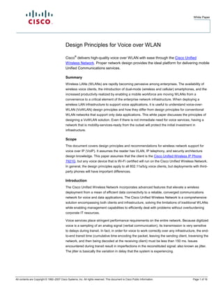
At the edge of each voice cell, the received signal strength indication (RSSI) measurement should
be –67 dBm if you are using a Cisco Unified Wireless IP Phone 7921G. It is recommended that
you have RSSI above 35 at the edge of the cell, which is equivalent to –67dBm for optimum
preformance on the phone. This concept is illustrated in Figure 1.
Each cell in the network should overlap with the adjacent cells in order to facilitate uninterrupted
handoff as a client moves between cells and to provide a minimum service even in case of access
point failure. For a typical voice deployment, Cisco recommends a 15 to 20 percent overlap of a
given access point’s cell from each of the adjoining cells, as shown in Figure 1.
Figure 1. Cell Overlap Guidelines for 802.11 b/g
The RF Audit and Site Survey
The goal of any site survey should be to perform actual measurements of the RF environment
where the wireless network will be deployed. Unlicensed frequencies (2.4-GHz and 5-GHz
frequencies, especially the 2.4-GHz) can be “noisy” environments, with microwave ovens to radar
systems to Bluetooth vying for air time. With the advent of emerging RF technologies such as
sensor networks, this trend will continue.
The site survey and a spectrum analysis tool should provide a precise view into what other RF
activity is present. A site survey should be conducted using the same frequency plan intended for
the actual deployment. This provides a more accurate estimate of how a particular channel at a
particular location will react to the interference and to multipath propagation. The site survey
should be conducted with the voice client that will be deployed; each client has a unique RF
performance, so different clients will yield different results. The same is true for the radios and
All contents are Copyright © 1992–2007 Cisco Systems, Inc. All rights reserved. This document is Cisco Public Information. Page 5 of 16
- 6. White Paper
external or internal antennas in the infrastructure. In summary, access point and client selection
should be finalized prior to the site survey. As new client devices are added, a periodic update to
the site survey is a proactive step to help ensure that the RF network is optimized. Such updates
are part of step 8.
It is also advisable to conduct several site surveys, varying the times and days to ensure that a
comprehensive view of the RF domain is obtained. RF activity can be variable and depends on
many factors, including employee activity. The site survey should identify sources of RF
interference and variability in RF patterns due to physical building changes (for example, the
movement of machinery, the presence of elevator shafts) and employee movements (for example,
weekly all-hands meetings).
A clear view of the RF domain can help mitigate potential sources of interference. The site survey
should also identify areas within the deployment that may require additional capacity due to a
concentration of users or likelihood of co-channel interference.
Cisco’s Wireless Planning Tools
The Cisco Unified Wireless Network integrates radio resource management software, which works
together with the integrated network planning and design features in the Cisco Wireless Control
System (WCS). Cisco WCS provides integrated RF prediction tools that can be used to create a
detailed wireless LAN design, including access point placement, configuration, and performance
and coverage estimates. IT staff can import real floor plans into Cisco WCS and assign RF
characteristics to building components to increase design accuracy. Graphical heat maps help IT
staff visualize anticipated wireless LAN behavior for easier planning and faster rollout (Figure 2).
Figure 2. The Cisco WCS Deployment Planning Tool
The WCS deployment planning tool is ideal for general office environments. For challenging RF
environments such as those found in hospitals and manufacturing plants, Cisco’s Advanced
Services or Cisco Certified Partners have extensive experience and expertise in planning and
deploying voice over wireless. In addition, for manual verification of the wireless network, the Cisco
Unified Wireless IP Phone 7921G integrates site survey tools to enable the IT manager to display
a list of access points that are in range. This tool is useful for validating and troubleshooting
specific problem areas. In addition, internally stored logs and Web-accessible diagnostics are also
available on the phone, and spectrum analysis capabilities, along with a VoWLAN network
readiness tool (Figure 3), are available on the Cisco WCS.
All contents are Copyright © 1992–2007 Cisco Systems, Inc. All rights reserved. This document is Cisco Public Information. Page 6 of 16
- 7. White Paper
Figure 3. VoWLAN Network Readiness Tool
Access Point Location
The location of access points is an important characteristic in making the network ready for voice
services. In contrast to the traditional theory of access point deployment, which recommended
deploying for greatest range, the voice-ready approach recommends deploying for density, with as
many access points as possible covering a given area without creating excessive interference. The
preferred access point placement model places access points around the perimeter of the building
as well as in the center, as shown in Figure 4, for more complete coverage and greater
redundancy.
Figure 4. Voice-Ready Access Point Placement
As a guideline and starting point for site surveys, in a voice-ready WLAN, access points should be
deployed at a density of approximately one every 3000 square feet, as opposed to one every 5000
square feet used for data-only networks. So to calculate the number of access points required for
deployment, divide the total number of square feet to be covered by 3000 and you will have a good
starting point in your design. This level of density helps ensure that voice services have the
necessary RF coverage redundancy and throughput required to provide optimal service capacity.
Ideally, there will still be a site survey to maximize coverage and minimize interference.
Wireless endpoints and access points communicate via radios on particular channels. When
communicating on one channel, wireless endpoints are unaware of traffic and communication
All contents are Copyright © 1992–2007 Cisco Systems, Inc. All rights reserved. This document is Cisco Public Information. Page 7 of 16
- 8. White Paper
occurring on other nonoverlapping channels. The Cisco Unified Wireless Network monitors the
power output of each access point and will adjust the power according to the topology. In dense
deployments (deployments with many access points), each access point’s transmit power will be
lowered so as to limit co-channel interference with neighboring access points (Figure 5).
Figure 5. WCS Management of RF Environment
However, when you use the Cisco Unified Wireless IP Phone 7921G, Cisco recommends that you
keep the transmit power of the access point and the phone at the same level in order to avoid one-
way audio occurrences, which are a result of a mismatch between the reach of the signal. This can
be configured in one click with the Cisco Wireless Control System.
Voice Capacity Planning
The 802.11 wireless networking protocol uses a contention-based access algorithm. Based on this
access methodology, protocol overhead, bandwidth calculations, and wireless voice network
testing, Cisco has determined that with the IEEE’s 11-Mbps throughput limitation on 802.11b, a
single 802.11b wireless access point can support up approximately to seven active voice streams
using the G.711 codec or eight active voice streams using G.729 codec and also handle a
reasonable level of data traffic. An active phone session is one carrying on a conversation. A voice
client that is associated with an access point and not carrying on a VoIP session (that is,
conversation) is not considered active.
Within a cell with active voice traffic, the Cisco Unified Wireless Network is able to help ensure that
voice clients have appropriate access and resources. The Cisco Unified Wireless Network ensures
access using an advanced QoS standard known as call admission control (CAC). The Cisco
Unified Wireless Network controllers enable predictable CAC for the network. In the unified
network, the controller has a holistic view of all the clients in the network, along with the total
available call capacity between all access points on the same channel. This capability helps to
ensure that when a VoWLAN call is admitted into the Cisco Unified Wireless Network, there is
enough voice capacity across all access points. The result is more predictable, reliable voice
performance.
Another important requirement for wireless networking is the appropriate provisioning of
bandwidth. Bandwidth provisioning involves the bandwidth between the wired and wireless
networks as well as the number of simultaneous voice calls that an access point can handle.
Wireless access points typically connect to the wired network via a 100-Mbps link to an access-
layer switch port. While the ingress Ethernet port on the access point can receive traffic at 100
Mbps, the maximum throughput on an 802.11b wireless network (the protocol primarily used by
voice devices) is 11 Mbps. After taking into account the half-duplex nature of the wireless medium
All contents are Copyright © 1992–2007 Cisco Systems, Inc. All rights reserved. This document is Cisco Public Information. Page 8 of 16
- 9. White Paper
and the overhead (to learn more about voice bandwidth calculations, please refer to the Cisco
Unified Wireless IP Phone 7921G Design and Deployment Guide) of wireless headers, the
practical throughput on the 802.11b wireless network is about 7 Mbps. This mismatch in
throughput between the wired and wireless network can result in packet drops when traffic bursts
occur in the network.
Rather than allowing traffic bursts to send excessive traffic toward the access point only to have it
dropped by the access point, it is a good idea to rate-limit or police this traffic to a rate that the
wireless network can handle. Forcing the access point to drop excessive traffic causes increased
CPU utilization and congestion at the access point. Instead, limiting the traffic rate to 7 Mbps on
the link between the wired access-layer switch and the wireless access point helps ensure that
traffic is dropped at the access-layer switch, thus removing the burden from the access point. It is
important to note that, depending on the wireless network deployment, the practical throughput
might be less than 7 Mbps, especially if more than the recommended numbers of devices are
associated with a single access point.
Voice-Ready Wireless Infrastructure
Voice places unique requirements on the WLAN. The Cisco Unified Wireless Network supports
these requirements through software capabilities in the infrastructure, in the Cisco Unified
Wireless IP Phone 7921G, and in Cisco Compatible Extensions program clients. The following are
technological enhancements that you should implement when planning the voice services network.
Roaming
Roaming is integral to voice services on wireless networks. A wireless voice client must be able to
maintain its association from one access point to another securely and with as little latency as
possible. It is therefore important to understand what roaming is as it relates to infrastructure
requirements and how and when it occurs. It’s also important to know about the types of roaming
and how they differ.
To accommodate roaming, administrators need to carefully consider their IP addressing schemes
before deploying wireless voice clients. In particular, they need to consider how WLAN coverage
overlays with the Layer 2 and Layer 3 addressing within the IP network. A Layer 2 network is
defined as a single IP subnet and broadcast domain, while a Layer 3 network is defined as the
combination of multiple IP subnets and broadcast domains (Figure 6).
Figure 6. Layer 2 and Layer 3 Roaming
All contents are Copyright © 1992–2007 Cisco Systems, Inc. All rights reserved. This document is Cisco Public Information. Page 9 of 16
- 10. White Paper
Layer 2 Roaming—Roaming within the Same IP Subnet
Just as with a wired LAN infrastructure, when deploying VoWLAN, Cisco recommends enabling at
least two VLANs at the access layer. In a wireless LAN environment, the access layer includes the
access point and the first-hop access switch. Wireless networks should also separate the voice
and data service set identifiers (SSIDs) to ensure that voice traffic and its associated security
parameters are optimized and customized thanks to segregation from data traffic (for more
information, see the Secure Wireless Design Guide 1.0). In addition, as with voice endpoints on
wired LANs, wireless voice endpoints should be addressed using RFC 1918 private subnet
addresses. More than two VLANs can be used if several types of voice devices are available within
the network and have different security capabilities.
With the voice VLAN extended throughout the corporate network, every access point connected to
the network should be able to attach to the voice VLAN (as well as a data VLAN). Now, as clients
roam across the enterprise, they are able to maintain their connection without noticeable
interruption because they never leave the voice subnet and hence always have access to the
required network resources (default gateway, IP-private branch exchange [PBX], and so on).
Layer 3 Roaming—Roaming across IP Subnets
In cases where Layer 2 VLAN configuration is difficult, it is highly recommended that the capability
to roam be designed to operate across Layer 3 subnets. This eliminates the need to configure
Layer 2 VLANs that extend across the entire enterprise, and reduces the associated operational
configuration costs.
Cisco enables Layer 3 mobility through the use of mobility groups, which provide the mechanism
for pooling resources to facilitate this desired client behavior. A mobility group does more than just
define the RF connectivity of the client. It defines the infrastructure resources and their connectivity
to each other. If a client needs to seamlessly roam from one location to another, even across IP
subnets, the resources in those locations need to be in the same defined mobility group.
All contents are Copyright © 1992–2007 Cisco Systems, Inc. All rights reserved. This document is Cisco Public Information. Page 10 of 16
- 11. White Paper
When a wireless client associates and authenticates to an access point, wireless LAN controllers
track each client in its client database. In this way, when the client roams to another mobility group,
the client’s MAC and IP addresses, security context and associations, QoS contexts, WLAN IDs,
and associated access point are transferred to the new WLAN controller.
Figure 7 shows a wireless client roaming from one access point to another.
Figure 7. Client Roaming between Access Points
When the wireless client moves its association from one access point to another, the controllers
update the client database with the newly associated access point. If necessary, a new security
context and associations are established as well. This capability, coupled with the Cisco
Centralized Key Management (CKM) protocol, helps ensure that time-sensitive applications, such
as VoIP, can be fully mobile and secure with minimal roaming latency. With the controller-based
architecture of the Cisco Unified Wireless Network, it is possible for a client to roam from an
access point attached to one controller to an access point attached to a second controller. With
intercontroller roaming, the infrastructure can maintain these same roaming characteristics. In
addition, the Cisco Unified Wireless Network employs a Mobility Messaging Exchange protocol
between the controllers that is used to exchange the client information and maintain the call across
IP subnets. When the client associates to an access point joined to a new controller, the new
controller exchanges mobility messages with the original controller, and the client database entry
is moved to the new controller. New security contexts and associations are established if
necessary, and the client database entry is updated for the new access point. This process, as
well as the inter-access-point handoff, is transparent to the user (Figure 8).
Figure 8. Layer 3 Inter-Controller Roaming
All contents are Copyright © 1992–2007 Cisco Systems, Inc. All rights reserved. This document is Cisco Public Information. Page 11 of 16
- 12. White Paper
To enable mobility groups, the administrator simply defines which physical locations should be
included. As a general guideline, a single mobility group should encompass an area that covers 80
to 90 percent of user roaming patterns, because clients cannot seamlessly roam across mobility
groups. Thus, prior to enabling mobility groups, the deployment team must have a good
understanding of how users move throughout the building, and they should incorporate this
understanding into the creation of each mobility group.
Quality of Service (QoS) Considerations
QoS on a pervasive WLAN is much more than simply prioritizing one type of packet over another.
WLAN traffic is nondeterministic; channel access is based on a binary, backoff algorithm defined
by the IEEE 802.11 standard and is by nature variable, because it is based on the number of
clients that access the network. Mobility makes this challenge more difficult. The number of active
users in any location changes dynamically and cannot be addressed through the capacity
management tools used in wired networks. Meeting the WLAN QoS needs of mobile voice users
will determine the success or failure of the VoWLAN deployment.
QoS and VLANs
Cisco recommends using VLANs to separate voice traffic from data traffic. This serves two
purposes: security (discussed in the next section) and isolation of higher-priority voice traffic so
that it can be dealt with using maximum resources.
Separating voice from data requires a minimum of two VLANs, and an assigned SSID on the
WLAN for each VLAN. Using separate data and voice VLANs enables specific QoS settings on all
traffic on the voice VLAN to give it a higher QoS profile. The Cisco Unified Wireless Network
supports four levels of QoS over the air: platinum for voice, gold for video, silver for best effort (the
default), and bronze for background. You can configure the voice traffic WLAN to use platinum
QoS, assign the low-bandwidth WLAN to use bronze QoS, and assign all other traffic between the
remaining QoS levels. Separating traffic by VLAN and using the QoS profiles for VLAN traffic
reduces the chance of data clients crowding the voice WLAN and causing unnecessary traffic
overhead and delays.
Note that this is in addition to the previous RF recommendation of ensuring nonoverlapping
channels to avoid interference. It should not be misconstrued as a replacement for that
recommendation.
All contents are Copyright © 1992–2007 Cisco Systems, Inc. All rights reserved. This document is Cisco Public Information. Page 12 of 16
- 13. White Paper
The Cisco Unified Wireless Network also allows you to maintain a QoS profile for Layer 2 and
Layer 3 over wireless and wired network. Indeed, all WLAN traffic that passes between the access
point and the wireless LAN controller is encapsulated. However, this encapsulation maintains the
Layer 3 marking in the original packet. Once the packet is de-encapsulated at the access point or
wireless LAN controller, the original Layer 3 marking is again used by QoS mechanisms in the
network infrastructure. With this capability,, the network can achieve end-to-end QoS for voice
traffic, over the air and across the wired network.
IEEE 802.11e and Wi-Fi Multimedia
To improve the reliability of voice transmissions in this nondeterministic environment, Cisco
recommends the use of Cisco Unified Wireless IP Phone 7921G and any device that supports the
industry-standard IEEE 802.11e and is Wi-Fi Multimedia (WMM)-certified. WMM enables
differentiated services for voice, video, best-effort data, and other traffic. However, in order for
these differentiated services to provide sufficient QoS for voice packets, only a certain amount of
voice bandwidth can be serviced or admitted on a channel at any one time. If the network can
handle N voice calls with reserved bandwidth, when the amount of voice traffic is increased
beyond this limit (that is, to the N+1 call), the quality of all calls suffers.
Call Admission Control
The Cisco Unified Wireless Network supports CAC to police the call capacity on a “per-access-
point” basis. Cisco Unified Communications Manager. which performs the call processing functions
in a network, provides additional CAC features for the wired network, helping to ensure an end-to-
end CAC implementation. Cisco requires the use of Cisco Compatible Extensions clients to enable
the use of the traffic specification (TSpec) of the traffic flows for the calculation of call limits and
proper WLAN load balancing. The TSpec of each voice flow allows the system to allocate
bandwidth to client devices on a first-come, first-served basis and maintains a small reserve so
that mobile phone clients can roam into a neighboring access point (even though the access point
might otherwise be at “full capacity”). Once the limit for voice bandwidth is reached, the next call
will be load-balanced to a neighboring access point ,and the call will be completed without
affecting the quality of the existing calls on the channel.
The difficulty of providing a good CAC function is exacerbated the by pervasive-coverage cell
design recommended earlier. In a pervasive-coverage design, an RF channel can be shared by
several access points. With CAC enabled and the Cisco Unified Wireless IP Phone 7921G clients
in use, the Cisco Unified Wireless Network allows the resources to be globally managed by the
wireless network controller across all the adjacent access points. Thus, each access point is not
permitted to admit the same amount of voice traffic as it could if it were operating in isolation.
Access points employ MAC measurements from clients and neighboring access points to aid in
determining the amount of traffic on the RF channel and whether a new call should be admitted.
Security Design Considerations
When deploying a WLAN, security should be at the top of the priority list. The strict requirements
for voice in terms of packet delivery time and predictability, coupled with the ability for clients to
roam across access points and subnets, presents a challenge to security architectures.
Cisco Centralized Key Management and EAP-FAST for Fast Secure Roaming
To minimize the delay introduced by authenticating roaming clients, Cisco recommends using the
Extensible Authentication Protocol—Flexible Authentication via Secured Tunnel (EAP-FAST) with
Cisco Centralized Key Management. EAP-FAST is an 802.1x EAP framework for authentication
All contents are Copyright © 1992–2007 Cisco Systems, Inc. All rights reserved. This document is Cisco Public Information. Page 13 of 16
- 14. White Paper
that encrypts EAP transactions with a Transport Layer Security (TLS) tunnel. While similar to
Protected Extensible Authentication Protocol (PEAP) in this respect, it differs significantly in that
EAP-FAST tunnel establishment is based upon strong secrets that are unique to clients. These
secrets are called Protected Access Credentials (PACs), which the infrastructure generates using
a master key.
During roaming, reauthentication time back to the RADIUS server alone can take 500 ms or more.
To remedy this, Cisco recommends using Cisco Centralized Key Management, an innovative
solution to achieve access-point-to-access-point roaming latency of less than 100 ms. Cisco
Centralized Key Management permits the negotiation of a session key from a cached master key
and avoids the need to go back to the authentication, authorization, and accounting (AAA) server
during a roam. When the client roams, it informs the infrastructure that it has roamed and the
infrastructure forwards the keying material to the new access point. The efficiency of EAP-FAST
with Cisco Centralized Key Management helps ensure maximum protection with minimum
transaction time. Cisco Centralized Key Management is available with the Cisco Unified Wireless
IP Phone 7921G, as well as any client that is compliant with Cisco Compatible Extensions
Version 4.
Secure Voice VLAN and SSID Design
Cisco VLAN technology separates the physical network into multiple logical networks. For secure
voice calls, Cisco recommends creating separate VLANs and SSIDs for voice. In turn, associating
the voice SSID with the voice VLAN creates a single, unified voice network across both the wired
and wireless networks with consistent security and QoS profiles. The WLAN controller will bridge
the traffic from the voice SSIDs to the voice VLANs. The primary advantage of this physical
separation of voice and data traffic is that traffic sent over the voice network is not visible to
insiders or outsiders connected to data network. The converse is also true.
Following are some of the ways that VLANs protect the voice system from security threats:
● Preventing toll fraud: Companies can apply different access control policies to their voice
VLAN: for example, authorizing employees on the manufacturing floor to access the data
segment but not the voice segment. Establishing a separate voice VLAN also prevents
employees from using another department’s VLAN for toll calls to avoid increasing their
own phone bills.
● Preventing denial-of-service (DoS) attacks: Most DoS attacks originate from a PC;
therefore, they cannot affect IP phones and call-processing servers connected to a
separate voice VLAN.
● Preventing eavesdropping and interception: Hackers typically eavesdrop on conversations
using a PC with special software to connect to the same VLAN as one or more parties in
the conversation. If voice participants are logically cordoned off, however, a hacker cannot
connect to the voice VLAN with a PC.
Following Best Practices for Wireless Security
With these voice-specific guidelines in place, Cisco has published best practices for general
wireless security. The paper “Five Steps to Securing Your Wireless LAN and Preventing Wireless
Threats” discusses best practices in a multilayered approach to secure the network—whether
wired or wireless—from unauthorized use through a WLAN link. These practices should be
validated against an organization’s own risk-management processes and complemented by a
strong security implementation.
All contents are Copyright © 1992–2007 Cisco Systems, Inc. All rights reserved. This document is Cisco Public Information. Page 14 of 16
- 15. White Paper
Together, this combination can protect the organization from inappropriate resource use, theft, and
damage to the company’s reputation with customers and partners. For a comprehensive
evaluation of your organization’s network security posture, Cisco Advanced Services consultants
and Cisco Certified Partners can analyze your network security in reference to industry best
practices, identifying vulnerabilities that could threaten your business. Based on in-depth analysis,
Cisco offers recommendations on how to improve your overall network security and prioritizes
actions for remediation, which should be complemented by strong access control and security
policies.
Voice Over WLAN Client Requirements
A voice-ready WLAN requires the client to be capable of supporting basic 802.11 standards for
QoS. In addition, to use the voice-ready Cisco infrastructure for enterprise roaming, management,
and security features, Cisco recommends the voice clients be either a Cisco Unified Wireless IP
Phone 7921G or any voice-capable Wi-Fi device with, ideally, the advanced voice features
available through the Cisco Compatible Extensions program. Table 2 provides a summary of the
voice-related features supported by Cisco Compatible clients.
Table 2. Voice Features Supported by Cisco Compatible Clients
Feature Function Benefit Cisco Compatible
Extensions Version
Cisco Centralized A device on the network creates a Eliminates any noticeable delay that is Version 3
Key Management cache of security credentials for Cisco normally introduced by security
Centralized Key Management- authentication during roaming.
enabled client devices on the subnet.
The device forwards the client’s
security credentials to the access
point that the client is destined for,
and the process of roaming is
reduced to a two-packet exchange
between the roaming client and the
destination access point rather than
being an extended process of re-
authenticating all the way back to a
RADIUS server in the network.
Voice metrics Defines reporting elements of packet Allows for proactive management and Version 4
latency, packet jitter, packet loss, and problem isolation for VoWLAN using
roaming delay. quality metrics.
Call Admission Allocates bandwidth to client devices Maintains call levels for optimal QoS. Version 4
Control (CAC) on a first-come, first-served basis; If a network exceeds the capacity of a
also maintains a small reserve so that WLAN RF channel by even one call,
mobile phone clients can roam into a all calls on the channel will suffer.
basic service set (BSS) even though CAC is a method of preventing
the BSS would otherwise be at “full channel overload and load-balancing
capacity.” Access points employ MAC calls that is transparent to the user.
measurements from clients and
access points to aid in determining
the amount of traffic on the RF
channel and whether a new call
should be admitted.
Unscheduled U-APSD enables the phone to QoS feature extends the talk time Version 4
Automatic Power aggregate traffic in order to minimize battery life of mobile clients.
Save Delivery transitions from active to idle or sleep
(U-APSD) mode.
All contents are Copyright © 1992–2007 Cisco Systems, Inc. All rights reserved. This document is Cisco Public Information. Page 15 of 16
- 16. White Paper
Conclusion
A WLAN in an enterprise is no longer a luxury, but a necessary part of the IT infrastructure. With
IP telephony growing exponentially as enterprises grow and the wireless LAN being a natural
extension of the wired LAN, it is critical to implement wireless technology that enables mobile
workforce productivity without handicapping the corporate IT staff. Following some simple design
best practices, a successful VoWLAN network is possible with today’s network solutions.
The Cisco Unified Wireless Network employs advanced features that help the enterprise establish
a voice-ready infrastructure. To deliver a WLAN that provides VoIP service with the quality
performance and availability expected from a wired LAN, it is critical to follow some best practices
and use the best WLAN technology available for voice deployments. The Cisco Unified Wireless
Network lets businesses and other organizations bring the mobility and flexibility of wireless
networking to their voice communications systems.
For more information please visit: www.cisco.com/go/wirelessvoice
Printed in USA C11-358627-01 9/07
All contents are Copyright © 1992–2007 Cisco Systems, Inc. All rights reserved. This document is Cisco Public Information. Page 16 of 16