1. GEO-N
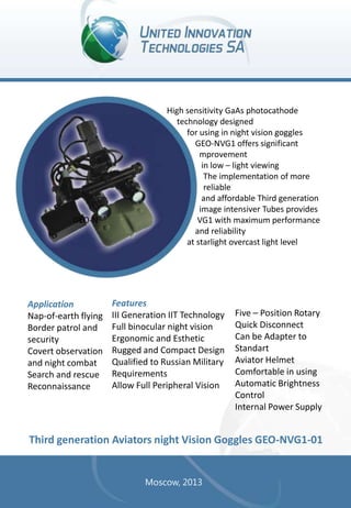
Application
Nap-of-earth flying
Border patrol and
security
Covert observation
and night combat
Search and rescue
Reconnaissance
High sensitivity GaAs photocathode
technology designed
for using in night vision goggles
GEO-NVG1 offers significant
mprovement
in low – light viewing
The implementation of more
reliable
and affordable Third generation
image intensiver Tubes provides
VG1 with maximum performance
and reliability
at starlight overcast light level
Features
III Generation IIT Technology
Full binocular night vision
Ergonomic and Esthetic
Rugged and Compact Design
Qualified to Russian Military
Requirements
Allow Full Peripheral Vision
Five – Position Rotary
Quick Disconnect
Can be Adapter to
Standart
Aviator Helmet
Comfortable in using
Automatic Brightness
Control
Internal Power Supply
Third generation Aviators night Vision Goggles GEO-NVG1-01
Moscow, 2013
2. Теchnical characteristics
Image intensifier tube gen
III:
Photocathode Type
Photocathode
Sensitivity
Radiant (λ=830 nm)
Gain
GaAs
System specification:
Scene illumination
1500 μA/lm
Magnification
150 mA/W
Field of View
25000
Exit Pupil
5 x10⁻⁴ lux ÷ 0.1 lux
1*
38° (min)
8 mm
Signal/Noise Ratio
E=10-4 lux
17
Resolution
23 mm
Center Resolution
45 mm-1
Resolution
0,65 cy/mrad
Useful Cathode
Diameter
17,5 mm
Objective lens
Input faceplate
Glass, Ñ57
Output Faceplate
Dimension
Fiber Optics
Inverter
∅ 36,75 mm x 31
mm
Aperture
Eyepiece Lens
Voltage required
Power source
25 mm
1/1,2
25 mm
27 V DC 50mA
Helicopter electrical
wiring system
Battery
Mechanical adjustment
range:
Vertical
16 mm
Fore & Aft
24 mm
Interpupillary
Eyepiece
Diopter
54 ÷ 72 mm
+2D -4D
2 AA size Alkaline (316)
Weight
540 grams
3. The Aviator’s Night Vision
Goggles (NVG) «GEO-NVG101» provide the crew with an
opportunity of viewing the terrain
at night (illumination range
5•10-4 ÷ 10-1 lux) and realization
of the following action:
takeoff;
hovering;
flying at heights from 50 up to
200 m with the visual control of a
terrain;
- approach and execution of landings
with a contact of ground on the nonequipped
and not covered platforms.
All military Russian helicopter pilots now benefit
from the ergonomic end technological
enhancements
incorporated into «GEO-NVG1-01» goggles.
High sensitivity GaAs photocathode technology designed
for using in night vision goggles offers significant
improvement in low – light viewing
The implementation of more reliable and affordable Third Generation
Image Intensifier Tubes (IIT Gen. III) provides with maximum
performance and reliability at starlight overcast light level.
The objective lenses utilize the integrated minus-blue filter which is compatible with
helicopter equipped green-yellow-red cockpit lightings.
Application
Nap-of-earth flying
Border patrol and
security
Covert observation
and night
combat
Search and rescue
Reconnaissance
Features
III Generation IIT Technology
Full binocular night vision
Ergonomic and Esthetic
Rugged and Compact Design
Qualified to Russian Military
Requirements
Allow Full Peripheral Vision
Five – Position Rotary
Quick Disconnect
Can be Adapter to Standard
Aviator Helmet
Comfortable in using
Automatic Brightness
Control
Internal Power Supply
Third generation Aviators night Vision Goggles GEO-NVG1-01
4. Теchnical characteristics
Image intensifier tube gen
III:
Photocathode Type
GaAs
Photocathode Sensitivity
Scene illumination
5 x10⁻⁴ lux ÷ 0.1 lux
1500 μA/lm
Magnification
1*
150 mA/W
Radiant (λ=830 nm)
Gain
System specification:
Field of View
40°
25000-45000
Exit Pupil
8 mm
20
Eye relief
23 mm
Signal/Noise Ratio E=104 lux
Center Resolution
50 mm-1
System distortion
Less than 2 %
Useful Cathode
Diameter
17,5 mm
Resolution
0,65 cy/mrad
Input faceplate
Glass, C57
Focal length
Output Faceplate
Fiber Optics
Inverter
∅ 36,75 mm x 31
mm
Dimension
F Number
25 mm
1,2
Input voltage
27 volts DC
Input currant
50 mA
Power source
Helicopter electrical
wiring system
Battery voltage
Weight
Mechanical:
Vertical
16 mm
Fore & Aft
24 mm
Interpupillary
Eyepiece
Diopter
54 ÷ 72 mm
+2D to -4D
2 AA size Alkaline
(316),
2.0 to 3.0 volts DC
550 grams
5. The Aviator’s Night Vision
Goggles (NVG) GEO-NV - III
-NVG provide the crew with
an opportunity of viewing the
terrain at night (illumination
range 5•10-4 ÷ 10-1 lux) and
realization of the following action:
takeoff;
hovering;
approach and execution of landings
with a contact of ground on the
non equipped
and not covered platforms.
High sensitivity GaAs photocathode
technology designed for using in night vision
goggles offers significant improvement in low
– light viewing
The implementation of more reliable and affordable
Third Generation Image Intensifier Tubes (IIT Gen. III) provides with maximum
performance and reliability at starlight overcast light level. The objective lenses
utilize the integrated minus-blue filter which is compatible with helicopter
equipped green-yellow-red cockpit lightings.
Aplication
Nap-of-earth flying
Search and rescue
Reconnaissance
Features
III Generation IIT Technology
Full binocular night vision
Ergonomic and Esthetic
Rugged and Compact Design
Quick Disconnect
Can be Adapter to
Standard Aviator Helmet
Comfortable in using
Automatic Brightness
Control
Internal Power Supply
Third generation night Vision Goggles GEO-NV - III - NVG
6. Теchnical characteristics
Image intensifier tube gen
III:
Photocathode Type
GaAs
Photocathode
Sensitivity
System specification:
Scene
illumination
5 x10⁻⁴ lux ÷ 0.1 lux
1300 μA/lm
Gain
1*
130 mA/W
Radiant (λ=830 nm)
Magnification
Field of View
38°
25000
Exit Pupil
8 mm
Signal/Noise Ratio
E=10-4 lux
17
Eye relief
23 mm
Center Resolution
36 mm-1
System distortion
Less than 2 %
Useful Cathode
Diameter
17,5 mm
Resolution
0,65 cy/mrad
Input faceplate
Glass, C57
Focal length
Output Faceplate
Fiber Optics
Inverter
∅ 36,75 mm x 31
mm
Dimension
25 mm
F Number
1,2
Input voltage
27 volts DC
Input currant
50 mA
Power source
Battery voltage
Mechanical:
16 mm
Fore & Aft
24 mm
Interpupillary
Eyepiece
Diopter
2 AA size Alkaline
(316),
2.0 to 3.0 volts DC
Weight
Vertical
Tilt adjustment
Helicopter electrical
wiring system
10 0
52 ÷ 72 mm
+2D to -4D
550 grams
7. Теchnical characteristics
Supervision out of cabin space
and helicopter pilotage at night
with maintenance of indication flight
parameters of movement, position in
space and the additional information.
Helicopter take off and landing on not
equipped platforms in night conditions.
Searching people and technics.
Covert flight of helicopters at night.
High quality image in natural night light conditions
by application of III-rd generation IIT allowing to
improve vision in low light level conditions considerably.
Comfortable vision in NVG is provided by high quality
eyepieces, great value of output diameters and their disposal
from design elements.
Simple moving in not-working position.
Possibility to use independent power sources.
SYSTEM FEATURES
Stereoscopic vision in a wide angular field.
Convenient fastening on a protective helmet and individual regulation for operator’s eyes,
realized by four mounts.
Ergonomic indication of additional parameters provided by application of OLED micro
display.
Manual brightness control of additional parameters
Aviators night vision goggles with micro display for flight
parameters visualization GEO-NVG1-VI
8. Теchnical characteristics
Main characteristics:
Scene illumination
Mechanical characteristics:
5·10-4-0,1 lx
Magnification
1*
Field of view
38 °
Adjustment range
Diopter
+2 ÷ -2 dptr
Interpupillary
Eyepiece
54 - 72 mm
Exit pupil
12 mm
Vertical
16 mm
Eye relief
23 mm
Horisontal
24 mm
Resolution
1,0 cycle/mrad
Focal length
26 mm
Aperture
Required Voltage
1:1,2
27 V (50 mА)
Weight
730 g
IIT characteristics:
Photocathode
type
Sensitivity:
- Light
- radiant (830
nm)
EBI
Signal/Noise ratio
(Е=10-4 lx)
GaAs
1500 μА/lm
150 mА/W
6·10-11 lx
17
Photocathode
diameter
17,5 mm
Resolution
45 mm-1
Input faceplate
Output faceplate
Dimensions
Glass С-57
Inverter fiberoptics
Element
∅ 36, 75-31 mm
12. Теchnical characteristics
PERFOMANCE CHARACTERISTICS
IIT 58G-01 with
useful
diameter 18 mm
min
IIT 58G-01 with useful
diameter 18 mm
max
min
Photocathode Sensitivitya
Luminous (2854OK) μA/Im
1300
1600
1800
Radiant (λ = 830 nm) mA/W
120
150
180
25000
35000
35000
3*10-3
3*10-3
Luminous Gain (1-5) x 10 -4 lux
Background brightness cd/m
Signal-to-Noise Ratio (E=10-4 lux)
16
18
25
Center Resolution lp/mm
40
45
50
Output Background cd/m2
3-8
3-8
3-8
Modulator transfer function, %
2,5 Lp/mm
7,5 Lp/mm
15,0 Lp/mm
0,86
0,64
0,35
Weight, g
0,90
0,70
0,45
85
85
PHOTOCATHODE
Type of photocatocathode
GaAs
GaAs
Spectral Range
530 ÷
930
530 ÷ 930
Glass, C57
Glass, C-57
Input optics
Cathode Diameter, mm
∅ 17.5
∅ 18
∅ 17.5
PHOSFOR SCREEN
Type
Image output
Dimension, mm
KC-527
KC-527
Inverter
Inverter
∅ 36,7x31
∅ 36,7x31
13. Photosensitive modules, consisted
of III generation image intensifier
tubes with negative electron
affinity photocathode,
coupled with CCD matrix
intended for night vision
TV systems.
All of four modules is working in
next spectral ranges:
PSM V-IR - 0,5-0,9 μm;
PSM UV - 0,2-0,35 μm;
PSM IR1 - 0,4-1,1 μm;
PSM IR2 - 0,95-1,65 μm.
All modules have on output standard TV signal - 1V 75Om.
Resistance to environment conditions GOST RM 20.39.414.1
Photosensitive modules on base of image
intensifier tubes III generation
14. Теchnical characteristics
PERFOMANCE CHARACTERISTICS
Spectral range
PSM V-IR
PSM UV
PSM IR1
PSM IR2
Μm
0,5-0,9
0,2-0,35
0,4-1,1
0,95-1,65
μA/lm
2500
-
400
-
mA/W
220
-
50
-
- radiant (1060 nm)
mA/W
-
-
2,5
-
Work TV resolution
Tvl
450
400
400
450
20
-
9
-
Sensitivity:
-
Light
radiant (850 nm)
Signal/Noise ratio (E-10-4 lx)
Power supply (voltage)
V
12
12
12
12
Power supply (current)
mA
250
250
250
250
Output frame format
Pixel
768x576
768x576
768x576
768x576
Bit
12
12
12
12
Threshold irradiance
W/m2
-
5 10-7
-
-
Work irradiance
W/m2
-
5 10-4
-
-
%
-
-
-
2
Digital capacity of output signal
Quantum efficiency (1540 nm)
15. FILTERS are intended for adaptation
aircraft interior lighting
compatible with Aviator’s
Night Vision Goggles (NVG)
using Third Generation Image
intensifier Tubes (IIT Gen. III) for
providing flight at day and night
time (with or without NVG) at
different Natural illuminance
levels. FILTERS are intended for
adaptation aircraft interior lighting
compatible with Aviator’s Night Vision
Goggles (NVG) using Third Generation
Image Intensifier
Tubes (IIT Gen. III) for ensure operation aircraft
compatible lighting with NVG rage at night time at low-light-level. FILTERS
are designed to meet all the requirements of Russian standard &
International standard MIL-STD-3009.
OVERALL PERFORMANCE
Adaptation of aircraft interior lighting is substitution of standard (red) light
filters on adapted (compatible with NVG) color (green, yellow and red)
FILTERS immediately in consoles, panels, instrument and display panel
lighting and etc.
FILTERS can be quantified with any reference source. SPU «Geophisika»
supplies filter data with the actual source specified by customers
application.
Brightness adjustment of the aircraft interior lighting compatible with NVG is
carried out the assistance of voltage control, allowing to adjust a voltage of a
power supply of lamps
from 10 V up to 27 V.
Aircraft Filters Compatible
with Night Vision Goggles
17. IR sources are intended for
the installation in the exterior
lighting systems. They provide
a safe single and group flying of
helicopters in the night with the
NVG system used only.
The guidance is done at the
various levels of night light
exposure on a terrain. IR sources
work in a Covert mode. In this
mode supervision of lights from
outside and in the limited distances is
provided by using a NVG. Unaided
detection of the lights is excluded.
All IR sources represent a tactical replaceable complete set which is subject
to installation for
performance of special tasks. IR sources are a NVG
compatible Infra-Red replacement for wing and tail, formation and blade
screwing light bulbs. They provide a simple economical means of temporarily
converting visible lights to IR for covet operations. Remove the incandescent
lamps, insert IR sources and modification is complete.
IR sources are equipped with the current stabilization system, which is
particularly useful in case of ambient environment temperature changes.
IR Sources for the Exterior Lighting Systems in
NVG Compatible Helicopter
18. Теchnical characteristics
IR Sources Specification:
IR Source Type
Exterior Lighting Type
ГЕО-ИИС014
Formation
ОПС-57
Supply Operating Voltage
ГЕО-ИИС013
Tail tip
XC-39
Tail tip
XC-62
ГЕО-ИИС016
Wing tip
БАНО-64
Light
blades of
the
bearing
screw
Ми-8
АМТ/МТВ
(5-8) RMS
AC 400 Hz
27 VDC
7,5 RMS
AC 400 Hz
11 mA
8 mA
Peak Emission Wavelength
IR Output Radiation on axis)
ГЕО-ИИС017
(24-28) V DC
Nominal Operating Voltage, B
Current by Nominal
Operating
Voltage
ГЕО-ИИС015
8 mA
15 mA
15 mA
(905 ± 5) nm
1,5 W/sr
1 W/sr
1 W/sr
2 W/sr
1,5 W/sr
19. Light sources are intended
for installation in the exterior
lighting system. The sources
provide secure both single and
formation day-night piloting of
helicopters. Piloting is feasible
both with and without usage of
the NVG under different terrain
lighting levels.
Light sources work in “Visible NVG
friendly” mode, which provides visual
supervision with a naked eye. It doesn’t
diminish the distance of NVG action and
reduces visibility of lights for a considerably distant observer with
NVG.
Setting the light sources on the board the helicopter:
doesn’t require changes in mounting dimensions
of used Exterior lighting system. Light sources are fully
interchangeable with the incandescent lamps;
requires changing the nominals of ballast resistors, controlling
the mode “bright/dull”;
supposes the presence adaptation of helicopter’s cockpit for using NVG.
Light sources are equipped with the current stabilization system, which is particularly
useful in case of ambient environment temperature changes.
Light sources are created for the usage in the items ОПС– 57, ХС – 62, ХС – 39,
БАНО – 64, МСЛ - 3 – 2с, lights of rotor blade. They satisfy the requirements of Russian
Federation standard and MIL - STD – 3009. Such products with established light sources
conform to the requirements of international aviation rules FAR p.29.
Light sources withstand all types of environmental exposures for the light sources of
the
external lightening system.
IR sources for an Exterior Lighting Systems in
NVG Compatible Helicopter
20. Теchnical characteristics
Light source Type
ГЕО-ИИА-001
ГЕО-ИИА-001
Exterior Lighting Type
Formation
ОПС-57
Tail tip XC-62
Supply Operating Voltage
ГЕО-ИИА-007
Tail tip XC-39
Wing tip
БАНО-64
10-32 V DC
Nominal Operating Voltage
Current by Nominal
Operating
Voltage
ГЕО-ИИА-005
27 V DC
150 mА
300 mА
150 mА
600 mА
Colour in Exterior Lighting
Type
of by FAR p.29
Yellow / Green
Aviation
white
Aviation
white
Aviation
green,
Aviation red
Luminous intensity on axis
10 cd
27 cd
10 cd
100 cd
10-6 /
3·10-7
W/(sr⋅sm2)
10-6
W/(sr⋅sm2)
10-6
W/(sr⋅sm2)
3·10-7
W/(sr⋅sm2)
NVIS radiance,
for brightness 50 cd/m2
Light source Type
ГЕО-ИИА-011
ГЕО-ИИА-012
ГЕО-ИИА-002
ГЕО-ИИА-010
Exterior Lighting Type
Anti collision
lights
МСЛ-3-2c
Light blades
of
Ка-52
Light blades of
Ми-8АМТ
Light blades
of
Ми-8АМТВ
Supply Operating Voltage
18-31 V DC
5-8 RMS AC 400 Hz
27 V DC
7,5-8 RMS AC 400 Hz
Nominal Operating Voltage
Current by Nominal
Operating
Voltage
Colour in Exterior Lighting
Type
of by FAR p.29
Luminous intensity on axis
NVIS radiance,
for brightness 50 cd/m2
650 mА
Aviation red
effective 400
cd
3·10-7
W/(sr⋅sm2)
65 mА
200 mА
200 mА
Aviation white
Aviation white
Aviation
white
3,5 cd
5 cd
5 cd
10-6
W/(sr⋅sm2)
10-6 W/(sr⋅sm2)
10-6
W/(sr⋅sm2)
21. Dual mode radiation sources are
intended for installation into the exterior
lighting system. Piloting is feasible
both with and without usage of
the NVG under different terrain lighting
levels. Dual mode radiation sources
work in “Visible NVG Friendly” mode with
an opportunity of switching the “Covert”
mode. This construction doesn’t have
analogues for all over the world.
“Visible NVG friendly” mode provides visual
supervision with a naked eye. It doesn’t
diminish the distance of NVG action and reduces
visibility of lights for a considerably distant
observer with NVG.
“Covert” mode provides supervision of lights from
outside in the limited distances, which eliminates the
unaided detection of the lights. Detection by considerably distant observer with NVG is
impossible.
Setting the dual mode sources on the board the helicopter :
doesn’t require changes in connecting sizes of used lights. Dual
mode sources are fully interchangeable with used incandescent lamp;
requires changing the nominal and scheme of switching the ballast resistors,
controlling the mode “bright/dull” and changing the selector for “bright/dull” to
“ bright /dull/covert ”;
supposes the presence adaptation of helicopter’s cockpit for using NVG.
Dual mode radiation sources have integrated current stabilization system from the raised
temperature of the environment. They satisfy the requirements of Russian Federation
standard and MIL
STD - 3009. Such products with established dual mode sources conform to the requirements
of international aviation rules FAR p.29.
Dual mode radiation sources are equipped with the current stabilization system, which is
particularly useful in case of ambient environment temperature changes.
Emitting sources withstand all types of environmental exposures for the light sources of the
external lightening system.
Installation of such sources in a heluopter turns it into a moltipurpose “nigpe” lighting complex.
IR sources for an Exterior Lighting Systems in
NVG Compatible Helicopter
22. Теchnical characteristics
General descriptions of IR- sources:
Dual mode radiation
source Type
Exterior Lighting Type
ГЕО-ИИД-018
ГЕО-ИИД-018
Formation ОПС-57
Total tip ХС-62
In “Visible NVG friendly”
mode
Supply Operating Voltage
10-32 V DC
Nominal Operating
Voltage
Current by Nominal
Operating Voltage
Colour in Exterior Lighting
Type of by FAR p.29
Luminous intensity on
axis
NVIS radiance, for
brightness 50 cd/m2
27 V DC
150 mА
300 mА
Yellow
Aviation white
10 cd
27 cd
10-6 W/(sr⋅sm2)
10-6 W/(sr⋅sm2)
In “Covert” mode
Supply Operating Voltage
Current by Operating
Voltage 6 V
Peak Emission
Wavelength
Radiant Intensity on axis
5,5-7,5 RMS AC 400 Hz
11 mA
8 mA
905±5 nm
1,5 W/sr
1 W/sr
23. Night and Day TV camera for helicopters
sighting system consists
of low-level TV system and Day TV
channel.
GEO-NTK4 is derived on base of
Third
Generation Image Intensifier Tube
(IIT Gen. III.) coupled with digital
CCD camera.
Third Generation Image Intensifier
Tube consists of: GaAs photocathode;
Micro channel
Plate (MCP) and Phosphor screen.
GEO-NTK4 has the Day channel, which
provides automatic transfer from night to day
Regime by the video signal level control.
GEO-NTK4 has a special digital processor for image enhancement
Opportunity to use the unguided weapon at day & night time.
High technology recognition & low cost.
Augmented operating range at the expense of usage IR spectral range & digital
processing of the “Night” & “Day” imagery.
Detection & recognition targets on the AMLCD.
Night & Day TV Camera Gyro stabilized System for
Helicopters GEO-NTK4
24. Теchnical characteristics
Technical specification:
Configuration
Television standard
Image intensifier tube Gen. III:
Night TV camera
Day TV camera
625 TV lines, 25
Hz
Photocathode type
GaAs
Photocathode
sensitivity:
TV dissector
Horizontal,
across-line
Luminous
Power consumption
12 W, 0,5 A
Radiant
Temperature of
exploitation
+50°C ÷ -40°C
Weight:
Night TV camera
Day TV camera
1800 μA/lm
180 mA/W
3x10⁻³ cd/m2
EBI
Gain
30000
1,7 kg
Signal/Noise ratio
(E=10-4 lux)
20
0,7 kg
Illumination range
(10-5÷10-1) lux
Dimensions:
Photocathode diameter
24,5 mm
45 mm -1
Night TV camera
225 x 87 x 90 mm
Resolution
Day TV camera
117 x 53 x 91 mm
Input faceplate
Operation range
(targetvehicle)
1.5 ÷ 2 km
Glass
Output faceplate
Fiber-optic plate
Spectral range
0.6 – 0.9 μm
Screen
Yellow-green
Effective scene
illumination
Range
5x10⁻³ ÷ 5x10⁴ lux
Weight
150 g
Field of view:
Day:
Night:
13,5° x 18°
TV channel:
8,4° x 11°
Resolution:
Day:
∅ 64 x 22 mm
Dimension:
Sensor type:
500 TV lines
Night:
350-400 TV lines
CCD matrix
Pixels number:
752 (H) x 582 (V)
Pixels size
- anti blooming
- gamma correction
- electronic shutter
4,6 mm x 6,4 mm
25. GEO-NTK4I is used for recognition
the away targets by
the operator on the TV monitor
thus the targets should be
preliminary detected with a radar
system.
GEO-NTK4I is derived on base of
Third Generation Image Intensifier
Tube coupled with digital CCD
camera.
Third Generation image intensifier
tube consists of: GaAs photocathode;
Micro channel Plate (MCP) and phosphor
screen.
GEO-NTK4I has the Day channel, which provides
automatic transfer from night to day regime by the video signal level control.
GEO-NTK4I has the special digital processor for image enhancement.
GEO-NTK4I is used for applying the unguided weapon at day & night time.
GEO-NTK4I based on the high technology.
GEO-NTK4I is used for acquiring and targeting short and intermediate range
targets.
GEO-NTK4I uses the TV monitor for detection & recognition targets.
GEO-NTK4I uses the digital processing the “night” imagery for increasing
detection range.
GEO-NTK4I has the low cost.
Active-pulsed Night Vision TV
Camera GEO-NTK-4 I
26. Теchnical characteristics
Technical specification:
Operating range (people
group)
System specification:
1.5 ÷ 2 km
Spectral range
0.53 – 0.93 μm
Effective scene
illumination range
Configuration
Night TV camera
Television standard
Day TV camera
5x10⁻⁴ ÷ 5x10⁴ lux
Field of view:
625 lines, 25 hz
TV dissector
Day:
1.1° x 1.5°
Night:
2° x 3°
Resolution:
Horizontal, across-line
Power consumption
12 W, 0.5 A
Temperature of
exploitation
+40°C ÷ -40°C
Weight TV camera
Day:
570 TV lines
Night:
11 kg
Dimensions TV camera
450 TV lines
Image intensifier tube III gen:
Photocathode
Type
GaAs
Photocathode
sensitivity:
Luminous
1800 μA/lm
180 mA/W
Signal/Noise
ratio
15
lux)
Gain
L13
Field of view:
9° x 15°
0,81 μm
36 lp/mm
120 HC
Fiber Optics
Output faceplate
Laser pulse length
Delayed laser gate
(0-15) μc
Input faceplate
Glass
Yellow-green
35000
Background
brightness
25 mm
Resolution
Screen
Pulsed Laser
Illuminator
Light wave
Photocathode
Diameter
Radiant
(E=10-4
Laser channel specification:
10-5 ÷ 10-1 lux
Operating
illumination
Range
350x310x230 mm
3x10⁻³
Gate pulse for IIT
Pulsed radiated power
Frequency
Supply voltage:
Power consumption:
Specification TV channel:
Detector
CCD matrix
Matrix size
4,6 x 6,8 mm
Pixels size
8,3 x 8,3 mcm
Pixels number
- Protection against
the optical jamming
- Electronic shutter
- Ggamma correction
752 x 582
5 μc
400 W
5 kHz
12 V
1.5 W
27. GEO – NTK 4D is used for
recognition the away targets by
the operation on the TV
monitor.
GEO – NTK 4D is derived on
base CCD camera.
Augmented operating range at
the expense of usage IR spectral
range & digital processing imagery.
High technology recognition & low cost.
Augmented operating range at the expense of usage IR spectral
range & digital processing imagery.
Day TV Camera GEO-NTK4D
28. Теchnical characteristics
Specification technical:
Television standard
TV dissector
Power consumption
625 TV lines, 25 hz
Horizontal, across-line
12 W, 0.2 A
Operating
temperature range
+55°C ÷ -50°C
Operating
illumination range
0,1 ÷ 200 lux
Resolution
500 TV lines
Sensor type:
CCD matrix
Pixel’s number:
752 (H) x 582 (V)
Pixel’s size
4,6 mm x 6,4 mm
Resolution
> 500 TV lines
Detektor
CCD Matrix
Matrix size
4,6 х 6,8 mm
Pixel’s size
8,3 х 8,3 mm
Pixel number
752 x 582
Placement in
consumer
ingress protection
Equipment
volume
29. GEO-PZR1 is intended for detection
and tracking the Air targets in
a night conditions on the upgraded
Complex. GEO-PZR1 is fixed on the
Air defence Complexes.
GEO-PZR1 has a special digital
processor for image enhancement.
High technology & low cost.
Fire by the defense complexes SA- 6
“KVADRAT”, SA-8 “OSA”, SA-11 “BUK”, SA-13
“STRELA-10”, SA-15 “TOR”
SA-19 “TUGUSKA” in a night conditions on heightened distances
in night conditions as possible.
Increasing detection distance by usage of IR spectral range & digital processing
of the “night” imagery.
Detection & recognition targets on the AMLCD..
Night TV-sighting system For Air defense
Complex GEO-PZR1
30. Теchnical characteristics
Technical specification:
Configuration
Image intensifier tube III generation:
Low-level TV
camera
Television standart
625 lines, 50 Hz
Horizontal, acrossline
TV dissector
Power supply
27 V, 0,5 A
Temperature of
exploitation
+50°С ÷ -40°C
Weight
15 kg
Camera
400 x 270 x 120 mm
Monitor
180 x 220 x 50 mm
Photocathode
GaSe
Photocathode
sensitivity:
Luminous
1800 μAIm (min)
Radiant (λ=830nm)
Gain
35000
Background
brightness
6 x 10⁻³ (cd/m2)
Signalnoise ration
(E=10-4)
Working illumination
range
Photocathode
diameter
TV channel:
-Gamma correction: Yes
Output window
- Antiblooming: Yes
Input window
Operation range (
targethelicopter
Mil Mi-8)
Spectral range
illumination range
Twister 180°
Glass
-Narrow
Resolution
Yellow
TV channel:
10 km
0.58-0.93 nm
5x 10⁻³ ÷ 0.93 nm
Field of view:
-Width
10-5 ÷ 10-1 lux
32 lpnm
Screen
Technical:
15 (min)
25 mm
Resolutions
-Electronic shutter: Yes
180 mAW (min)
8° (H) x 6° (V)
24,7° (H) x 18.5° (V)
350 ÷ 400 TV lines
Sensor type
Pixels number:
Working illumination
rage
CCD
725 (H) x 582 (V)
0.5 ÷ 150 lux
31. GEO-PZR2 is intended for detection
and tracking the Air targets in a
night conditions on the AMLCD
for applying of Air Defence
guided missiles of the pgraded
Complex
GEO-PZR2 is fixed on the Air
defence Complexes.
Increasing detection distance by usage of IR
spectral range & digital processing of the “night” & imagery
High technology & low cost.
Detection & recognition targets on the AMLCD
Night TV-sighting system
For Air defense Complex GEO-PZR2
32. Теchnical characteristics
Specification:
Image intensifier tube III general data:
Television standart
625 lines, 50 Hz
Photocathode
TV dissector
Horizontal, across-line
Photocathode sensitivity
Power supply
27 V, 0,6 A
Luminous
Temperature of
exploitation
+50°C ÷ -40°C
Radiant (λ=830 nm)
Weight
10 kg
Gain
Background
brightness
Dimensions
Camera
380 x 112.5 x 95 mm
Signalnoise ratio
(E=10-4 lux)
Monitor
294 x 245 x 92.5 mm
Working illumination
range
TV channel:
- Gamma correction: Yes
- Electronic shutter: Yes
- Antiblooming: Yes
Photocathode
diameter
Resolution
Output window
Input window
Screen
GaAs
1800 μAlm (min)
150 mAW (min)
35000
3x10⁻³ (cd/m2)
15
10-5 ÷ 10-1 lux
18mm
36 lpmm
Fiber-optic plate
Glass
Yellow
Recognition range (at the natural night
illumination ~ 5•10-2 lx and normal weather) of the:
- men in the foliage:
not less than 500 m
- cargo car:
not less than 800 m
33. Third generation night sight “GEO
- ZRK 1” is designed for using with
Russian portable air defense
missile systems : “IGLA” ,
“STRELA”. The night sight
“GEO - ZRK 1” extends using
Russian portable air defense
missile systems up to level of starlight
overcast. Complex is capable to detect air
targets at ranges up to 8km. The night range of detection in
starlight condition is achieved by the expense of application in the
Night Sight “GEO-ZRK” highly sensitive and low noise 25 mm Gen (III
+ I) Image Intensifier Tube (IIT), which consists of IIT GEN III with
GaAs photocathode without Microchannel Plate (MCP), coupled
with IIT Gen I. The wide field of view of thr “GEO - ZRK 1” allows the
sight to be used for local surveillance.
The Night Sight “GEO - ZRK 1” adapter braket can be attached and
removed quickly.
Night Sight for portable Air Defense Complex GEO-ZRK1
34. Теchnical characteristics
General technical specification:
Spectral response
580 - 900 nm
Field of View
24°
Magnification
1,8
Resolution
Gain (adjusted)
Voltage
Battery live
Power source
2,1 cy/mr
1600…8000
2,2-3,5 V
8 hours
2V AA alkaline
Objectiv lens:
- Focal length
Aperture
55 mm
1:1,7
Eyepiece:
- Focal length
Eye relief
Output diameter
Diopter adjustment
Dimension
30,5 mm
25 mm
7 mm
+4…-6 dptr
300 x 200 x 96 mm
Weight
1.6 kg
- with adapter
1.9 kg
35. GEO-KPP is intended for estimation
of light leakage to provide
adaptation of the aircraft
lighting compatible with
Aviator’s Night Vision Goggles
(NVG) on the basis of Third
Generation Image Intensifier
Tubes (IIT Gen. Ill)
Test Equipment for Estimation of the
Compatibility Aircraft Interior Lighting with
Night Vision Goggles GEO-KPP
37. Visual supervision of objects at
night. Explaining on the ground
and water. Individual
adjustment under the
operator eyes. Border patrol
and security Ergonomic and
Esthetic Application of the
independent power supply
Pocketscope GEO M
38. Теchnical characteristics
System specification:
Terrain
illumination
Magnification
Field of View
Diopter
adjustment
Voltage
Power supply
Working time in
normal climatic
conditions
Image intensifier tube Gen. III:
5 x10⁻⁴ lux ÷ 0.1 lux
Photocathode Type
1* 2* 3*
40° 22,3° 13,6°
+5,5 D -4,5 D
3V
GaAs
Photocathode Sensitivity
Luminous
Radiant (λ=830 nm)
Gain
1500 μA/lm
150 mA/W
25000
2 AA size Alkaline (316)
Signal/Noise Ratio
E=10-4 lux
20
not less 10 h
Center Resolution
45 mm-1
Useful Cathode
Diameter
17,5 mm
Input faceplate
Glass, С57
Output Faceplate
Dimension
Fiber Optics Inverter
∅ 36,75 mm x 31 mm
39. Onboard weight-measuring system
(OWMS) is designed to measure
the load of heavy vehicles. In
case of exceeding the allowable
load it alarms. The information
about the vehicle is recorded on the
flash drive and could be transferred
to PC via USB or wireless.
OWMS provides information on
cargo weight and distribution of cargo weight on
the axes of the vehicle. These parameters are calculated from the data
obtained from sensors based on micromechanical accelerometers that are
part of OWMS.
The device displays also date, time and operating time of the vehicle in hours.
The device has built-in battery, rechargeable from the car power grid.
OWMS performs self-control of sensors serviceableness, communication lines
and in case of the presence of faults will display the diagnostic information on
the display.
The amount of memory provides the recording of the output parameters for
365 days.
On-board information measuring system
40. MAIN FEATURES:
Control and indication unit of the OWMS is made in a standard
head unit size as used for heavy-duty trucks manufactured by
“KAMAZ” group or any other (single DIN head unit);
error of weight measuring not more than 5% of the range of
measurement;
reading stored information under given protocol via USB or
wireless.
41. Micromechanical helmet–
mounted system of orientation
(HSO) is designed for
automatic definition of
angular coordinates
{ϕX; ϕY; ϕZ} of the boresight
line in the coordinate
system of
the flying machine and transferring
these coordinates to the onboard complex of
radio-electronic equipment of the flying machine. The boresight line
is observed at a turn of a head and matching the target with the
image of shooting mark. MSISO for HMSTI at demonstration stand
1. Personal computer with “HSO” software;
2. Autocollimating mirror;
3. Reference node consisting of the attitude heading
reference system and autocollimating mirror;
4. Optical Theodolite;
5. Micromechanical helmet attitude heading reference
system.
Micromechanical helmet attitude heading reference system
Micromechanical Helmet-mounted system of orientation
for system of targeting and indication
42. Теchnical characteristics
Specifications of HSO:
Range of measurement the angular
coordinates of the boresight line
Azimuth:
Elevation:
Roll:
The accuracy of measurement
the angular coordinates of the
boresight line
Δ ϕY = 3,0°
Δ ϕZ = 1,5°
Δ ϕX = 1,5°
ϕY= ± 110°
ϕZ= ± 80°
ϕX= ± 60°
43. Tiltmeters based on
MEMS - accelerometers
are designed measuring of the
tilt angle of any objects or
surface relief relative to
the lo cal horizon. Features:
small dimensions, weight
and power consumption.
Fields of application:
Motor vehicle and civil engineering:
traffic safety systems;
sensors for controlling threshold value of angle;
Oil and Gas Industry and robotic complexes:
control of drilling tools, pipelines and processing equipment;
on-line monitoring of buildings and environment;
Medicine:
tilt angle sensors for medical beds, tables and invalid chairs;
medical robotics complexes.
Aviation Industry:
Electronic quadrant for mounting of helicopter equipment.
Tiltmeters based on mems-accelerometers
44. Теchnical characteristics
APPLICATIONS
Automobile
transport
and construction
machinery
Medicine
Military robotic
Complexes
Aviation
Industry
Linear
acceleration
Range
± 10 g
±2g
± 1,7 g
± 1,7 g
Accuracy of linear
acceleration
Measurement
0,5%
0,5%
0,1%
-
Two-Axes angles
measurement
Range
± 70°
± 90°
± 60°
± 45°
Angular position
measurement
Error
0,3°
0,5°
0,1°
0,05°
∅ 49 x 25 mm
∅ 32 x 25 mm
∅ 32 x 25 mm
140 x 140 x 60
mm
12 V
12 V
12 V
12 V
Temperature
Range
-40 + 85°C
-10 + 70°C
-40 + 85°C
16 ÷ 35°C
Interface
CAN/RS232
RS232
RS232
RS232
PARAMETERS
Dimensions
Voltage Supply (V)
45. Measuring the distance to the
object, its geographical coordinates
within a few seconds accuracy;
- Displaying parameters (date,
time, distance and geographical
coordinates) of the object of
observation in real time in the camera viewfinder or on the camera
LCD;
- Full HD video recording
(1920x1080px) and pictures of the
remote object with superimposed
coordinate information
at the bottom of the frame;
Small dimensions and weight of the device;
Hand held or tripod mount.
1. Model of the device with a camera
2. Prototype of the device with a video camera and a tablet
PC
Fields of application:
protection of state and
administrative boundaries;
patrolling of the territory;
08.12.2009 / Distance: 350 m Object: Lon.: 37,2347
Lat .:55,4567 H. 124 10:45:78
Azimith: 12 Observer: Lon.: 37,2447 Lat .:55,4667 H. 156
Observing device for determining the geographical
coordinates of remote object With the micromechanical
strapdown inertial navigation system
46. Теchnical characteristics
General description:
Composition
DSLR camera, laser range finder, GPS/
Glonass receiver, strapdown integrated
naviga- tion system MEMS-based, module of
information pro- cessing, microdisplay with
collimating optics
Time of measurement
0,3 s
Mass
3 kg
Operating temperature
0 ÷ 40 °C
Range of distance measurement
+5 ÷ 40 °C
The accuracy of determining
geographi- cal coordinates of the
remote object
± 2” for latitude and longitude,
±100 m for height
Overall dimensions
280 x 230 x 175 mm
Technical data:
Type of laser
The accuracy of determining the distance
Class 1, eye safe,
λ=905 nm
±1m
Video frame rate
30, 25, 20 Hz
Video frame size
1920 x 1080
image size
3872 x 2592
The accuracy of the observer’s coordinates
Detection
The range of measured azimuth
The accuracy of azimuth defenition*
The measurement range of pitch and roll
Angles
11 m
0–360є
± 2°
± 70°
* Is reached under the pre-calibration and the absence of
external magnetic fields in the
area of measurement.