
Recommended
More Related Content
Similar to MIDAS-GEN_Flat_Slab_tutorial.pdf
Similar to MIDAS-GEN_Flat_Slab_tutorial.pdf (20)
Recently uploaded
Recently uploaded (20)
MIDAS-GEN_Flat_Slab_tutorial.pdf
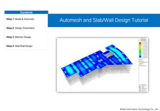
- 1. Contents Step 1: Model & Automesh Step 2: Design Parameters Step 3: Member Design Step 4: Slab/Wall Design Automesh and Slab/Wall Design Tutorial Midas Information Technology Co., Ltd.
- 2. Midas Information Technology Co., Ltd. Overview Step 00 9 m 16 m 9 m 23 m 5 m 6 m 7 m 2 m 12.5 m Typical Floor Plan 3 m 3 m 3 m 3 m 3 m Sectional Elevation
- 3. Midas Information Technology Co., Ltd. Eurocode-1:2005 • Beam : Concrete Grade C25/30 • Column: Concrete Grade C25/30 • Wall: Concrete Grade C30/37 Designation Story Section Number Column Dimension (mm) Column 1~5F 2 400 x 400 Designation Section Number Section Dimension (mm) Girder 1 500 x 400 Designation Thickness Number Thickness Dimension (mm) 1 200 2 250 Step 00 Girder sections Column section dimension Wall thickness Materials Applied Code Details of the Building
- 4. Midas Information Technology Co., Ltd. Load Details Dead Load Self Weight Weight Density: 1 kN/m3 Live Load Pressure Load Shopping areas : 4.0 kN/m2 Office areas : 2.0 kN/m2 Wind Load X-dir./ Y-dir. Eurocode-1(2005) Terrain Category : II Response Spectrum Load X-dir./ Y-dir. Eurocode-8(2004) Spectrum Parameters: TYPE 1 Ground Type : B Importance Factor : 1.0 Step 00 Details of the Building Applied Load
- 5. Midas Information Technology Co., Ltd. Step 01 Procedure 2 3 1 File > Open Project… Select “flat slab.mgb”. Click [Open] button. Opening the Pre-generated Model File 3 Opening the Pre-generated Model File 2
- 6. Midas Information Technology Co., Ltd. Procedure Model > Mesh > Auto-mesh Planar Area Method : Line Elements Type : Quad + Triangle Mesh Size : Length : 0.5 m Material : 1:C25/30 Thickness : 1:0.200 Domain : 1 Select by Window > Front View Select Roof-Line Iso View > Click [Apply] 1 Step 01 2 3 4 5 6 7 8 9 1 2 3 4 5 6 7 8 9 Auto-mesh Planar Area Generate meshed elements for slabs Specify meshed area for auto- meshing (Line elements method).
- 7. Midas Information Technology Co., Ltd. Procedure Top View > Select Wall-Line Activate > Iso View Method : Planar Elements Material : 2:C30/37 Thickness : 2:0.250 Domain : 2 Select Wall > Click [Apply] Domain : 3 Select Wall > Click [Apply] 1 Step 01 2 3 4 5 6 1 2 3 4 5 6 Auto-mesh Planar Area Generate meshed elements for walls Specify meshed area for auto- meshing (Line elements method).
- 8. Midas Information Technology Co., Ltd. Procedure Step 01 Auto-mesh Planar Area Model > User Coordinate System > X-Z Plan Origin : 39, 4, 0 Click : [Apply] > [Close] Model > Grids > Define Point Grids dx, dy : 1, 1 Click : [Apply] > [Close] 1 2 3 4 1 3 4 2 Generate meshed elements with opening Specify meshed area for auto- meshing (Nodes method).
- 9. Midas Information Technology Co., Ltd. Procedure Step 01 Auto-mesh Planar Area Model > Mesh > Auto-mesh Planar Method : Nodes Material : 2:C30/37 Thickness : 2:0.250 Display Node Numbers (Toggle On) Domain : 4 Click Nodes > Click : [Apply] > [Close] > Activate All 1 2 3 4 5 6 1 2 3 4 5 6 Generate meshed elements with opening Specify meshed area for auto- meshing (Nodes method).
- 10. Midas Information Technology Co., Ltd. Procedure Tree Menu > Work > Domain1 [1] > Double Click Load > Pressure Loads Load Case Name : LL Direction : Local z Loads : P1 : -4.0kN Shopping areas D1 : Areas in general retail shops Click [Apply] > [Close] 1 Step 02 2 3 4 5 1 2 3 4 5 Pressure Loads 6 6 Apply floor loads
- 11. Midas Information Technology Co., Ltd. Procedure Tree Menu > Work > Domain1 [2] > Double Click Load > Pressure Loads Load Case Name : LL Direction : Local z Loads : P1 : -2.0kN Office areas Click [Apply] 1 Step 02 2 3 4 5 1 2 3 4 5 Pressure Loads 6 6 Apply floor loads
- 12. Midas Information Technology Co., Ltd. Procedure Model > Building > Building Generation Number of Copies : 4 Distance(Global z) : 3 m Operations : Click [Add] Select All > Click [Apply] 1 Step 02 2 3 4 5 1 2 3 4 5 Building Generation
- 13. Midas Information Technology Co., Ltd. Procedure Model > Building > Story > Auto Generate Story Data Select Click [OK] Click [Close] 1 Step 02 2 3 4 1 4 Auto Generate Story Data 2 3
- 14. Midas Information Technology Co., Ltd. Procedure View > Activities > Active Identity Click : Story > 4F Click : [Active] > [Close] 1 Step 02 2 3 1 Active Identity 2 3
- 15. Midas Information Technology Co., Ltd. Procedure Model > Domain > Define Sub-Domain Click : [2] Rebar Dir.(CCW) : Dir.1 : 135, Dir.2 : 135 Click : [Modify] > [Close] 1 Step 02 2 3 4 1 Define Sub-Domain 4 2 3 Define sub-domain for design Reinforcement direction can be specified by sub-domains.
- 16. Midas Information Technology Co., Ltd. Procedure Load > Lateral Loads > Wind Loads > Click [Add] Load Case Name : WX Wind Load Code : Eurocode-1(2005) Wind Load Direction Factor : X-Dir. : 1, Y-Dir. : 0 Click [Apply] Load Case Name : WY Wind Load Direction Factor : X-Dir. : 0, Y-Dir. : 1 Click [OK] Click [Close] 1 Step 02 2 3 4 5 6 1 2 3 4 5 6 7 7 Wind Loads
- 17. Midas Information Technology Co., Ltd. Procedure Load > Response Spectrum Analysis Data > Response Spectrum Functions Click [Add] Click [Design Spectrum] Design Spectrum : Eurocode-8(2004) Spectrum Type : Horizontal Design Spectrum Click [OK] Click [OK] Click [Close] 1 Step 02 2 3 4 5 6 1 7 Response Spectrum Functions 2 3 4 6 5 7 8 8
- 18. Midas Information Technology Co., Ltd. Procedure Load > Response Spectrum Analysis Data > Response Spectrum Load Cases Load Cases Name : RX Excitation Angle : 0 Check : EURO2004 H-Design Click [Add] Load Cases Name : RY Excitation Angle : 90 > Click [Add] Click [Eigenvalue Analysis control] > [OK] Click [Close] 1 Step 02 2 3 4 5 6 1 Response Spectrum Load Cases 7 2 3 4 6 5 7
- 19. Midas Information Technology Co., Ltd. Procedure Results > Combinations > Concrete Design > Auto Generation Click [OK], Click [Close] Perform Analysis 1 Step 02 2 3 1 2 3 Auto Generation
- 20. Midas Information Technology Co., Ltd. Step 03 Procedure Design > Concrete Design Parameter> Concrete Design Code Click [OK] Design > Concrete Code Design > Column Design Sorted by : Member > Click [Close] 1 2 1 2 3 4 3 4 Column Design
- 21. Midas Information Technology Co., Ltd. Step 03 Procedure Design > Concrete Design Parameter> Modify Column Rebar Data Main : P32 End : P16@200 / Center : P16 Click [Add/Replace] > [Close] 1 2 1 3 Modify Column Rebar Data 2 3
- 22. Midas Information Technology Co., Ltd. Step 04 Procedure Design > Meshed Slab/Wall Design > Slab/Wall Load Combinations Click [OK] 1 2 1 2 Slab/Wall Load Combinations Slab/Wall Load Combination Select the load combinations for the slab/wall element design.
- 23. Midas Information Technology Co., Ltd. Step 04 Procedure Design > Meshed Slab/Wall Design > Design Criteria for Rebar For Slab Design : Angle 1 : 0.03 m, 0.03 m Angle 2 : 0.05 m, 0.05 m Click [OK] 1 2 3 1 2 3 Design Criteria for Rebar Specify rebar size Enter the standard sizes of rebars used in the design of reinforcement for slab/wall elements.
- 24. Midas Information Technology Co., Ltd. Step 04 Procedure View > Activities > Active Identity Click : Story > 3F Check : +Below Click : [Active] > [Close] 1 2 3 Active Identity 2 3 1
- 25. Midas Information Technology Co., Ltd. Step 04 Procedure Design > Meshed Slab/Wall Design > Slab Flexural Design Select [Avg. Nodal]. Check [As_req(m^2/m)] Check on One-Way Flexure Design option and click […] button Defined Cutting Lines [Add] Click [Apply] 1 2 3 1 3 4 Slab Flexural Design Slab Flexural Design Check the flexural design results for slab elements in contour. 4 5 6 5 Display the bending moments of the floor slab elements along a cutting line, and produce the design results of reinforcement. 2 6
- 26. Midas Information Technology Co., Ltd. Step 04 Procedure Design > Meshed Slab/Wall Design > Slab Flexural Design Select [Avg. Nodal]. Click [Design Result] Click [Design Force] Click [Update Rebar] 1 2 3 4 1 3 4 5 Slab Flexural Design Produce the detail flexural design results of slab elements in a text format. Produce the flexural design forces of slab elements in a tabular format. Update the rebar quantity for each slab element. The updated rebar data is used for strength verification. 5 2
- 27. Midas Information Technology Co., Ltd. Step 04 Procedure Design > Meshed Slab/Wall Design > Slab Flexural Design Check [Resistance Ratio] Load Cases/ Combinations : cLCB5 Select [Avg. Nodal]. Check [Dir.1] Click [Apply] Click [Update Rebar] 1 2 3 4 5 1 2 3 5 6 Slab Flexural Design The ratio of the design moment to the moment resistance when the designed rebar spacing is applied. 6 4 7 7
- 28. Midas Information Technology Co., Ltd. Step 04 Procedure [Smoothing] Slab Flexural Design For practical design, smooth moment distributions are preferred. By selecting the smoothing option, the program can consider the smooth moment in slab design. Element: Design results are displayed using the internal forces calculated at each node of elements. (no smoothing) Avg. Nodal: Design results are displayed using the average internal nodal forces of the contiguous elements sharing the common nodes. Element: Design results are produced for moments at each node of slab elements. (no smoothing) Width: Design result of slab elements at each node is produced using the average of the bending moments of the contiguous slab elements with the specified width. (Example) Design force for Node. EN21 In one plate element, 4 internal forces exist. For the element E2, member forces exist at the node EN21, EN22, EN23 and EN24. Following equations show how the smoothing option works for the node EN21. (Assume that rebar direction is selected as Angle 2 for Width smoothing direction.) (1) Element + Element: EN21 (2) Avg. Nodal +Element: (EN12+EN21+EN33+EN44)/4 (3) Element + Width 2m: (EN11+EN12+EN21+EN22)/4 2m 1 2 EN73 EN72 EN83 EN82 (4) Avg. Nodal + Width 2m: {(EN11+EN34+EN72+EN83)/4 + (EN12+EN21+EN33+EN44)/4 + (EN22+ EN43+ EN51+EN64)/4 }/3 Avg. Nodal of EN33 = (EN12+EN21+EN33+EN44)/4 Width 2m of EN33 = (EN33+EN34+EN43+EN44)/4 2m Average Nodal and Width smoothing Design > Meshed Slab/Wall Design > Slab Flexural Design
- 29. Midas Information Technology Co., Ltd. Step 04 Procedure Design > Meshed Slab/Wall Design > Slab Flexural Design Check [Wood Armer Moment] Load Cases/ Combinations : CBC : cLCB6 Check [Dir.1] Click [Apply] 1 2 3 4 5 1 2 3 4 5 Slab Flexural Design Display the Wood Armer Moments in contour.
- 30. Midas Information Technology Co., Ltd. Step 04 Procedure [Wood Armer Moment] Slab Flexural Design From the analysis results, following plate forces about the local axis are calculated - mxx - myy - mxy In order to calculate design forces in the reinforcement direction, angle α and φ will be taken as following figure: x, y: local axis of plate element 1, 2: reinforcement direction α: angle between local x-direction and reinforcement direction 1 φ: angle between reinforcement direction 1 and reinforcement direction 2 Firstly, internal forces (mxx, myy and mxy) are transformed into the a-b coordinate system.
- 31. Midas Information Technology Co., Ltd. Step 04 Procedure [Wood Armer Moment] Slab Flexural Design Then, Wood-Armer moments are calculated as follows:
- 32. Midas Information Technology Co., Ltd. Step 04 Procedure Design > Meshed Slab/Wall Design > Slab Shear Checking Click [Apply] 1 2 1 2 Slab Shear Checking Slab Shear Checking Produce the two-way shear (punching shear) check results at the supports of slab elements or at concentrated loads and the one-way shear check results along the user-defined Shear Check Lines.
- 33. Midas Information Technology Co., Ltd. Step 04 Procedure [Punching Shear Check(By Force)] Slab Shear Checking In this method, the program takes the axial force in the column supporting the slab as the shear force (V_Ed). The basic control perimeter (u1) is taken at a distance 2d from the column face (as shown in the diagram below. The maximum shear force is calculated by multiplying V_Ed with shear enhancement factor β. The value of β is different for different columns. (as given in the code) The shear resistance of the slab (without shear reinforcement) at the basic control section is given by V_Rd,c = (0.18/γ_c)k(100*ρl*fck)1/3*(u1*d) , the value of ρl is assumed to be 0.02. If •V_Ed < V_Rd,c : section is safe in punching shear •V_Ed > V_Rd,c : provide shear reinforcement. Asw/sr = (v_Ed-0.75*v_Rd_c)*(u1*d) / (1.5*d*fywd_ef)
- 34. Midas Information Technology Co., Ltd. Step 04 Procedure [Punching Shear Check(By Stress)] Slab Shear Checking In these methods (The Stress Method), the Shear force along the critical section is taken and divided by the effective depth to calculate shear stress. Therefore there is no need to calculate β (Beta), to consider moment transferred to the column. (There are 4 plate elements intersecting at nodes. The nodes are marked by nomenclature of Grid Lines. As the center node is denoted by B2 , B on x-Axis and 2 on Y-Axis) When slab is defined as the plate element, the program calculated stresses only at the nodes, in the analysis. So we have the stresses at B1, B2, C2 etc. (see the figure above) are calculated by the program. Case 1 - To calculate stresses at the critical section that is u1 in the given figure, for example we take the point P in the figure which lies in a straight line. The stress at B1 and B2 are known. The values at these nodes are interpolated linearly to find the stress at point P . Case 2- Now if the point lies in the curve such as the point Q, then the software will divide the curve into 6 parts. At each point such as Q a tangent which intersects B1-B2 and C2-B2.The value of stresses at T and V are determined by linear interpolation of stresses which are known at for T (at B1 and B2) and for V (at C2 and B2). After knowing stresses at T and V the stress at Q is determined by linear interpolation of stresses at T and V.
- 35. Midas Information Technology Co., Ltd. Step 04 Procedure [Punching Shear Check(By Stress)] Slab Shear Checking (Method 1: Average by elements.) In this method the stresses at all the critical points is determined. The critical points divide the critical section into segments. The average value for all these segments is determined by dividing the stresses at the two ends of the segment by 2. After determining the average value for each segment, the maximum average value from all of the segments is reported as the Stress value for the critical Section. a,b are stresses at the segment ends. Average value for the segment will be (a+b)/2, and such average value for each segment is determined.
- 36. Midas Information Technology Co., Ltd. Step 04 Procedure [Punching Shear Check(By Stress)] Slab Shear Checking (Method 2: Average by Side) In this method stresses at all critical points is determined and then average stress value is calculated by weighted mean. To calculate weighted mean , For example we have 4 critical points a, b, c, d. - Stress at critical points: For example at ‘a’ its 9 - Average of the segment: For example in ‘a’ and ‘b’ its (15+9)/2 = 12 - Distance Between the critical points: For example between ‘a’ and ‘b’ its 8 - Final Stress = (12 * 8 + 17 * 10 + 15 * 6)/ (8+10+6), which is the weighted average. We divide the Critical section into 4 sides as shown in figure. The weighted mean value for each side is determined and then the maximum value out of the 4 sides A, B, C, D is reported as the stress value.
- 37. Midas Information Technology Co., Ltd. Step 04 Procedure Design > Concrete Design Parameter > Serviceability Parameter Select All Click [Apply] 1 2 1 2 Serviceability Parameter 3 3
- 38. Midas Information Technology Co., Ltd. Step 04 Procedure Design > Meshed Slab/Wall Design > Serviceability Load Combination Type Click [OK] > [Close] 1 2 Serviceability Load Combination Type 1 2 Serviceability load combination type is automatically assigned if ‘Auto Generation’ function has been used to generate load- combinations. If the user manually defined load combinations, serviceability load combination type must be defined by the user. If serviceability load combination type is not specified, Slab Serviceability Checking is not performed.
- 39. Midas Information Technology Co., Ltd. Step 04 Procedure Design > Meshed Slab/Wall Design > Slab Serviceability Checking Select [Avg. Nodal]. Check [Stress Checking] Check [Concrete] Click [Apply] 1 2 1 3 Slab Serviceability Checking Slab Serviceability Checking Produce the serviceability check results for slabs. 3 4 4 Display the compressive stress in the concrete. 5 2 5
- 40. Midas Information Technology Co., Ltd. Step 04 Procedure 1 3 Slab Serviceability Checking 4 6 Design > Meshed Slab/Wall Design > Slab Serviceability Checking Select [Avg. Nodal]. Check [Crack control] Check [Crack Width] Select [Value] Click [Apply] 1 2 3 4 Display the value of crack width. Crack control is not performed for slab elements for which thickness is less than 200mm. 2 5 5 6
- 41. Midas Information Technology Co., Ltd. Step 04 Procedure Design > Meshed Slab/Wall Design > Slab Serviceability Checking Select [Avg. Nodal]. Check [Deflection] Check [Creep] Select [Value] Click [Apply] 1 2 1 3 Slab Serviceability Checking 3 4 4 Calculate the deflection for the uncracked section and compare it with the allowable deflection (deflection for the cracked section is not available yet) . 6 2 5 6 5
- 42. Midas Information Technology Co., Ltd. Step 04 Procedure 2 4 5 Wall Design View > Activities > Active All Design > Meshed Slab/Wall Design > Wall Design Check [As_req(m^2/m)] Select [Avg. Nodal]. Select [Resistance Ratio]. Click [Apply] 1 2 3 Wall Design Perform the flexural design results for wall elements in contour. Display the area of the required reinforcement. Wall design is performed based on EN 1992-1-1:2004 Annex F (Tension reinforcement expressions for in-plane stress conditions). 3 4 5
- 43. Midas Information Technology Co., Ltd. Step 04 Procedure Design > Meshed Slab/Wall Design > Wall Design Click [Design Result] Click [Design Force] 1 2 3 1 2 3 Wall Design