Download to read offline


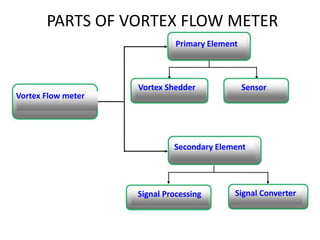


The document describes an experimental study on vortex shedding behind a trapezoidal bluff body using flow visualization. The study aims to calculate vortex formation length, identify the Strouhal number and wake width. Flow visualization is used to understand the complex vortex formation mechanism. An experimental setup is fabricated with a trapezoidal bluff body placed inside a circular pipe. Dye injection technique is employed to visualize vortex patterns. Various wake parameters will be derived from the flow visualization images to improve the understanding and design of vortex flow meters.


