B-1 connection diagram and installation instructions -feb2022
•
0 likes•19 views

B-1 connection diagram and installation instructions -feb2022
![Installation instructions
1- Perform a general inspection of the vehicle/mechanism to ensure all systems work nominally, such as engine oil and coolant levels are to
specifications, no engine malfunction indicator lights, no excessive noise or emissions, etc.
2- [Optional] Measure baseline exhaust emissions, e.g., exhaust gas opacity. Note the “Before” emission value.
3- Find a suitable location for the hydrogen kit components in the engine bay, to safely place and secure hydrogen cell [4], gas dryer [5], controller [3].
When choosing the location, avoid poorly-ventilated areas or placing the equipment in direct proximity to heat sources.
4- Securely mount hydrogen cell [4], gas dryer [5], and controller [3] using the rubberized brackets [22] and L-shaped supports [21].
5- Dismount air intake manifold [12], pierce, and install the hydrogen admission hose adapter [6]. The hydrogen admission point should be located
after the air filter [13] and the MAF sensor [14] (if present), but before the turbo [15]. Use heat resistant silicone to achieve secure, airtight connection.
6- Make electrical connections between battery [1] positive or other good-quality ‘permanent live’ [19] connection with black thick cable; battery
negative (mass) with red thick cable; and ‘ignition live’ [18] wires with red thin cable; all three feeding to 3-pin connector [7] in the controller [3].
7- Make electrical connections between the hydrogen cell [4] and the controller [3] via 4-pin connector [8]. Neatly arrange all electrical cabling to avoid
interference with moving parts in the engine bay.
8- Route, measure, cut to size, connect, and secure in place the hydrogen supply tubing [11] to make connections between the hydrogen cell [4], the
gas dryer [5], and the adapter [6]. Use green and red marks on the gas dryer [5] for guidance: Red = ‘to engine’, Green = ‘to hydrogen cell’.
9- Prepare electrolyte by dissolving KOH flakes [24] in 550 ml of distilled water. Attention! Always add KOH to water, not the other way around! For
safety, always use your appropriate personal protective equipment (PPE).
10- Using the measuring syringe [23], transfer 100 ml of the electrolyte to gas dryer [5]. Transfer the remaining 450 ml of electrolyte to the hydrogen
cell [4]. Hand-tighten the red filling caps – do not use tools.
11- Start the engine. The system is operational when the Blue controller LED indicator is On, and bubbles are passing through gas dryer [5].
12- [Optional] Measure final exhaust emissions. Compare the “Before” and “After” values to quantify system’s efficacy.
Page 2: ANTISMOG B-1
Hydrogen Premix Kit
Installation Instructions
(Turn over to Page 1 for
connection diagram)
For technical assistance contact: ANTISMOG, chez Station F, 5 parvis Alan Turing, 75013 Paris, France | Tel. +33953996431 | Email: info@antismog.co | www.antismog.co
ATTENTION: Always add
KOH flakes to water, not the
other way around!
Always use appropriate PPE.
NOTICE: Dissolve the KOH granules by gradually adding them to distilled water
and stirring continuously. When KOH granules are dissolved in water, the
temperature increases. The recommended concentration is approximately 10%.
This concentration can be obtained by adding 35 g of KOH to 550 ml of distilled
water. After transferring the electrolyte to the hydrogen cell, the LED level
indicator does not light up (normal electrolyte level) or goes green (maximum
electrolyte level). During operation, distilled water must be added periodically;
using measuring syringe add 100 ml of distilled water, when the red LED lights up,
and the beep sounds (two long beeps, repeated three times).](data:image/gif;base64,R0lGODlhAQABAIAAAAAAAP///yH5BAEAAAAALAAAAAABAAEAAAIBRAA7)
Recommended
Recommended
More Related Content
Similar to B-1 connection diagram and installation instructions -feb2022
Similar to B-1 connection diagram and installation instructions -feb2022 (20)
More from ANTISMOG
More from ANTISMOG (20)
Recently uploaded
Recently uploaded (20)
B-1 connection diagram and installation instructions -feb2022
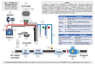
- 1. 23 Air filter MAF sensor Turbo Page 1: ANTISMOG B-1 Hydrogen Premix Kit Connection Diagram (Turn over to Page 2 for installation instructions) Engine Air intake manifold Exhaust Battery Ignition Controller - + 1 2 4 5 6 7 8 9 10 11 Legend: 1- Battery; 2- Ignition key; 3- Controller; 4- Hydrogen cell; 5- Gas dryer (bubbler); 6- Hydrogen hose adapter; 7- 3-pin connector; 8- 4-pin connector; 9- Hydrogen supply check valve; 10- Pressure compensation check valve; 11- Hydrogen supply hose; 12- Air intake manifold; 13- Air filter; 14- Mass Air Flow (MAF) sensor; 15- Turbo-compressor; 16- Engine; 17- Engine exhaust; 18- ‘Ignition Live’ wire; 19- ‘Permanent Live’ wire; 20- Controller LED indicators; 21- Two L-shaped mounting supports; 22- Three rubberized mounting brackets (2x Large, 1x Small); 23- Measuring syringe; 24- KOH flakes; 12 13 14 15 16 18 17 3 19 20 22 21 24 KOH Sounds Description Two long beeps – 3-second pause – two long beeps… Low electrolyte level – add 180 ml of distilled water. Three short beeps – three long beeps… Overheating of the controller or the hydrogen cell. Two long beeps – two short beeps… Loss of electrolyte level signal – check the connection (red cable) LED colour Description YELLOW Correct voltage and correct polarity detected. Voltage range 9-17 Volt. AMBER (ORANGE) Conditions are met for hydrogen gas production. Goes off 8-12 seconds after the voltage falls below 12.8 volts. GREEN Maximum electrolyte level – remove some electrolyte. May go on and off while vehicle is moving – this is normal. RED Low electrolyte level – add 180 ml of distilled water. BLUE Normal hydrogen production. For technical assistance contact: ANTISMOG, chez Station F, 5 parvis Alan Turing, 75013 Paris, France | Tel. +33953996431 | Email: info@antismog.co | www.antismog.co
- 2. Installation instructions 1- Perform a general inspection of the vehicle/mechanism to ensure all systems work nominally, such as engine oil and coolant levels are to specifications, no engine malfunction indicator lights, no excessive noise or emissions, etc. 2- [Optional] Measure baseline exhaust emissions, e.g., exhaust gas opacity. Note the “Before” emission value. 3- Find a suitable location for the hydrogen kit components in the engine bay, to safely place and secure hydrogen cell [4], gas dryer [5], controller [3]. When choosing the location, avoid poorly-ventilated areas or placing the equipment in direct proximity to heat sources. 4- Securely mount hydrogen cell [4], gas dryer [5], and controller [3] using the rubberized brackets [22] and L-shaped supports [21]. 5- Dismount air intake manifold [12], pierce, and install the hydrogen admission hose adapter [6]. The hydrogen admission point should be located after the air filter [13] and the MAF sensor [14] (if present), but before the turbo [15]. Use heat resistant silicone to achieve secure, airtight connection. 6- Make electrical connections between battery [1] positive or other good-quality ‘permanent live’ [19] connection with black thick cable; battery negative (mass) with red thick cable; and ‘ignition live’ [18] wires with red thin cable; all three feeding to 3-pin connector [7] in the controller [3]. 7- Make electrical connections between the hydrogen cell [4] and the controller [3] via 4-pin connector [8]. Neatly arrange all electrical cabling to avoid interference with moving parts in the engine bay. 8- Route, measure, cut to size, connect, and secure in place the hydrogen supply tubing [11] to make connections between the hydrogen cell [4], the gas dryer [5], and the adapter [6]. Use green and red marks on the gas dryer [5] for guidance: Red = ‘to engine’, Green = ‘to hydrogen cell’. 9- Prepare electrolyte by dissolving KOH flakes [24] in 550 ml of distilled water. Attention! Always add KOH to water, not the other way around! For safety, always use your appropriate personal protective equipment (PPE). 10- Using the measuring syringe [23], transfer 100 ml of the electrolyte to gas dryer [5]. Transfer the remaining 450 ml of electrolyte to the hydrogen cell [4]. Hand-tighten the red filling caps – do not use tools. 11- Start the engine. The system is operational when the Blue controller LED indicator is On, and bubbles are passing through gas dryer [5]. 12- [Optional] Measure final exhaust emissions. Compare the “Before” and “After” values to quantify system’s efficacy. Page 2: ANTISMOG B-1 Hydrogen Premix Kit Installation Instructions (Turn over to Page 1 for connection diagram) For technical assistance contact: ANTISMOG, chez Station F, 5 parvis Alan Turing, 75013 Paris, France | Tel. +33953996431 | Email: info@antismog.co | www.antismog.co ATTENTION: Always add KOH flakes to water, not the other way around! Always use appropriate PPE. NOTICE: Dissolve the KOH granules by gradually adding them to distilled water and stirring continuously. When KOH granules are dissolved in water, the temperature increases. The recommended concentration is approximately 10%. This concentration can be obtained by adding 35 g of KOH to 550 ml of distilled water. After transferring the electrolyte to the hydrogen cell, the LED level indicator does not light up (normal electrolyte level) or goes green (maximum electrolyte level). During operation, distilled water must be added periodically; using measuring syringe add 100 ml of distilled water, when the red LED lights up, and the beep sounds (two long beeps, repeated three times).