Swan(sea) Song – personal research during my six years at Swansea ... and bey...
Sech1920 1200112979886874-3
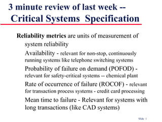
1. Slide 1
3 minute review of last week --
Critical Systems Specification
Reliability metrics are units of measurement of
system reliability
Availability - relevant for non-stop, continuously
running systems like telephone switching systems
Probability of failure on demand (POFOD) -
relevant for safety-critical systems -- chemical plant
Rate of occurrence of failure (ROCOF) - relevant
for transaction process systems - credit card processing
Mean time to failure - Relevant for systems with
long transactions (like CAD systems)
2. Slide 2
3 minute review of last week --
Hazard and risk analysis stages
Hazard identification
Risk analysis and hazard classification
Hazard decomposition
• Decompose hazards to discover their potential root causes
Risk reduction assessment
• Define how each hazard must be taken into account when the
system is designed
3. Slide 3
3 minute review of last week --
Critical systems development
Fault minimisation
• Dependable and repeatable development process
• PL with strict typing and run-time checking
• Avoid error-prone constructs like goto
Fault tolerance
• Fault recovery
• Forward recovery -- repair the corrupted system state
• Backward recovery -- back to the known safe state
• Fault-tolerant architectures
• N-version programming
• Recovery blocks
4. Slide 4
Verification:
"Are we building the product right"
The software should conform to its
specification
Validation:
"Are we building the right product"
The software should do what the user
really requires
Ch. 19 -- Verification and
Validation
5. Slide 5
Is a whole life-cycle process - V & V must be
applied at each stage in the software process.
The V & V process
Formal
specification
High-level
design
Requirements
specification
Detailed
design
Program
Prototype
Dynamic
validation
Static
verification
6. Slide 6
Software inspections Concerned with analysis of
the static system representation to discover
problems (static verification)
• May be supplement by tool-based document and code analysis
Software testing Concerned with exercising and
observing product behaviour (dynamic
verification)
• The system is executed with test data and its operational
behaviour is observed
Static and dynamic verification
7. Slide 7
Can reveal the presence of errors NOT their
absence
A successful test is a test which discovers one
or more errors
The only validation technique for non-functional
requirements
Should be used in conjunction with static
verification to provide full V&V coverage
Program testing
8. Slide 8
Defect testing
• Tests designed to discover system defects.
• A successful defect test is one which reveals the
presence of defects in a system.
• Covered in Chapter 20
Statistical testing
• tests designed to reflect the frequence of user inputs.
Used for reliability estimation.
• Covered in Chapter 21
Types of testing
9. Slide 9
V& V goals
Verification and validation should establish
confidence that the software is fit for purpose
Level of confidence depends on system’s purpose,
user expectations and marketing environment
• Software function: The level of confidence depends
on how critical the software is to an organisation
• User expectations: Users may have low expectations
of certain kinds of software
• Marketing environment: Getting a product to market
early may be more important than finding defects in
the program
10. Slide 10
Defect testing and debugging are distinct processes
Verification and validation is concerned with establishing
the existence of defects in a program
Debugging is concerned with locating and repairing errors
Debugging involves formulating a hypothesis about
program behaviour, then testing them to find the errors
Testing and debugging
Locate
error
Design
error repair
Repair
error
Re-test
program
Test
results Specification Test
cases
11. Slide 11
Careful planning is required to get the most out of
testing and inspection processes
Planning should start early in the development
process
The plan should identify the balance between
static verification and testing
Test planning is about defining standards for the
testing process rather than describing product tests
19.1 V & V planning
12. Slide 12
The structure of a software test plan
The testing process
Requirements traceability
To-be-tested items list
Testing schedule
Test recording procedures
Hardware and software requirements
Constraints
13. Slide 13
The V-model of development
Requirements
specification
System
specification
System
design
Detailed
design
Module and
unit code
and tess
Sub-system
integration
test plan
System
integration
test plan
Acceptance
test plan
Service
Acceptance
test
System
integration test
Sub-system
integration test
14. Slide 14
19.2 Software inspections
Very effective technique for discovering errors
Involve people examining the source
representation to discover anomalies and defects
Do not require execution of a system --
so may be used before implementation
May be applied to any representation of the system
(requirements, design, test data, etc.)
They reuse domain and programming knowledge
so reviewers are likely to have seen the types of
errors that commonly arise
15. Slide 15
Inspections and testing
Inspections and testing are complementary and not
opposing verification techniques
Many different defects may be discovered in a
single inspection. In testing, one defect may mask
another so several executions are required
Inspections can check conformance with a
specification but not conformance with the
customer’s real requirements
Inspections cannot check non-functional
characteristics such as performance, usability, etc.
16. Slide 16
Inspection pre-conditions
A precise specification must be available
Syntactically correct code must be available
An error checklist should be prepared
Team members must be familiar with the
organisation standards
Management must accept that inspection will
increase costs early in the software process
Management must not use inspections for staff
appraisal
17. Slide 17
Inspection procedure
System overview presented to inspection team
Code and associated documents are
distributed to inspection team in advance
Inspection takes place and discovered errors noted
Modifications are made to repair discovered errors
Re-inspection may (or may not) be required
Inspection
meeting
Individual
preparation
Overview
Planning
Rework
Follow-up
18. Slide 18
Inspection teams
Made up of at least 4 members
Author of the code being inspected
Inspector who finds errors, omissions and
inconsistencies
Reader who reads the code to the team
Moderator who chairs the meeting and notes
discovered errors
Other roles are Scribe and Chief moderator
19. Slide 19
Inspection checklists
Checklist of common errors should be used to
drive the inspection
Error checklist is programming language
dependent
The 'weaker' the type checking, the larger the
checklist
Examples: Initialisation, Constant naming, loop
termination, array bounds, etc.
20. Fault class Inspection check
Data faults Are all program variables initialised before their values are used?
Have all constants been named?
Should the lower bound of arrays be 0, 1, or something else?
Should the upper bound of arrays be equal to the size of the array or
Size -1?
If character strings are used, is a delimiter explicitly assigned?
Control faults For each conditional statement, is the condition correct?
Is each loop certain to terminate?
Are compound statements correctly bracketed?
In case statements, are all possible cases accounted for?
Input/output faults Are all input variables used?
Are all output variables assigned a value before they are output?
Interface faults Do all function and procedure calls have the correct number of
parameters?
Do formal and actual parameter types match?
Are the parameters in the right order?
If components access shared memory, do they have the
same model of the shared memory structure?
Storage management
Faults
If a linked structure is modified, have all links been correctly
reassigned?
If dynamic storage is used, has space been allocated correctly?
Is space explicitly de-allocated after it is no longer required?
Exception
management faults Have all possible error conditions been taken into account?
21. Slide 21
Inspection rate
500 statements/hour during overview
125 source statement/hour during individual
preparation
90-125 statements/hour can be inspected
Inspecting 500 lines costs about 40 man-hours
Inspection is therefore an expensive process
but still less than half the testing costs
Sessions no longer than 2 hours
22. Slide 22
19.3 Automated static analysis
Static analysers are software tools for source text
processing
They parse the program text and try to discover
potentially erroneous conditions and bring these to
the attention of the V & V team
Very effective as an aid to inspections. A
supplement to but not a replacement for
inspections
23. Slide 23
Static analysis checks
Fault class Static analysis check
Data faults Variables used before initialisation
Variables declared but never used
Variables assigned twice but never used
between assignments
Possible array bound violations
Undeclared variables
Control faults Unreachable code
Unconditional branches into loops
Input/output faults Variables output twice with no intervening
assignment
Interface faults Parameter type mismatches
Parameter number mismatches
Non-usage of the results of functions
Uncalled functions and procedures
Storage management
faults
Unassigned pointers
Pointer arithmetic
24. Slide 24
Stages of static analysis
Control flow analysis. Checks for loops with
multiple exit or entry points, finds unreachable
code, etc.
Data use analysis. Detects uninitialised
variables, variables written twice without an
intervening assignment, variables which are
declared but never used, etc.
Interface analysis. Checks the consistency of
routine and procedure declarations and their
use
25. Slide 25
Stages of static analysis
Information flow analysis. Identifies the
dependencies of output variables. Does not
detect anomalies itself but highlights
information for code inspection or review
Path analysis. Identifies paths through the
program and sets out the statements executed in
that path. Again, potentially useful in the review
process
Both these stages generate vast amounts of
information. Must be used with care.
26. LINT static analysis
138% more lint_ex.c
#include <stdio.h>
printarray (Anarray)
int Anarray;
{
printf(“%d”,Anarray);
}
main ()
{
int Anarray[5]; int i; char c;
printarray (Anarray, i, c);
printarray (Anarray) ;
}
139% cc lint_ex.c
140% lint lint_ex.c
lint_ex.c(10): warning: c may be used before set
lint_ex.c(10): warning: i may be used before set
printarray: variable # of args. lint_ex.c(4) :: lint_ex.c(10)
printarray, arg. 1 used inconsistently lint_ex.c(4) ::
lint_ex.c(10)
printarray, arg. 1 used inconsistently lint_ex.c(4) ::
lint_ex.c(11)
printf returns value which is always ignored
27. Slide 27
Use of static analysis
Particularly valuable when a language such as C is
used which has weak typing and hence many
errors are undetected by the compiler
Less cost-effective for languages like Java that
have strong type checking and can therefore detect
many errors during compilation
28. Slide 28
The name is derived from the 'Cleanroom'
process in semiconductor fabrication. The
philosophy is defect avoidance rather than
defect removal
Software development process based on:
• Incremental development
• Formal specification
• Structured programming
• Static verification using correctness arguments
• Statistical testing to determine program reliability.
19.4 Cleanroom software
development
29. Slide 29
The Cleanroom process
Construct
structured
program
Define
software
increments
Formally
verify
code
Integrate
increment
Formally
specify
system
Develop
operational
profile
Design
statistical
tests
Test
integrated
system
Error rework
30. Slide 30
Formal specification and inspections
The system specification is a state based model
and the inspection process checks the program
against this model
Programming approach is defined so that the
correspondence between the model and the system
is clear
Mathematical arguments (not proofs) are used to
increase confidence in the inspection process
31. Slide 31
Specification team. Responsible for developing
and maintaining the system specification.
C-requirements + Formal specifications
Development team. Responsible for
developing and verifying the software.
Software inspection + correctness arguments
Certification team. Responsible for developing
a set of statistical tests to exercise the software
after development. Reliability certification.
Cleanroom process teams
32. Slide 32
Results in IBM have been very impressive with
few discovered faults in delivered systems
Independent assessment shows that the
process is no more expensive than other
approaches
Fewer errors than in a 'traditional' development
process
Not clear how this approach can be transferred
to an environment with less skilled or less
highly motivated engineers
Cleanroom process evaluation
33. Slide 33
Key points
Verification and validation are not the same thing.
Verification shows conformance with
specification; validation shows that the program
meets the customer’s needs
Test plans should be drawn up to guide the testing
process.
Static verification techniques involve examination
and analysis of the program for error detection
34. Slide 34
Key points
Program inspections are very effective in
discovering errors
Program code in inspections is checked by a small
team to locate software faults
Static analysis tools can discover program
anomalies which may be an indication of faults in
the code
The Cleanroom development process depends on
incremental development, static verification and
statistical testing
35. Slide 35
10 minute break - a test devised
by a 13 years old
Can you find out the incorrect multiplications
without using a calculator ?
a) 67896
x 321
------------
27094616
b) 34675
x 603
------------
20909025
c) 47183
x 369
------------
17401527
36. Slide 36
10 minute break - a test devised
by a 13 years old
(X +|-|* Y) mod 9 = X mod 9 +|-|* Y mod 9
a) 67896
x 321
------------
27094616
b) 34675
x 603
------------
20909025
c) 47183
x 369
------------
17401527
0
6
8
7
0
0
6
0
0
• It can prove the presence not the absence of errors.
37. Slide 37
Ch 20 -- Software testing
Component testing (by developer)
• Testing of individual program components
• Tests are derived from the developer’s experience
Integration testing (by testing team)
• Testing of groups of components integrated to create a system or
sub-system
• Tests are based on a system specification
Component
testing
Integration
testing
Software developer Independent testing team
38. Slide 38
20.1 Defect testing
The goal of defect testing is to discover defects in
programs
A successful defect test is a test which causes a
program to behave in an anomalous way
Tests show the presence not the absence of defects
Only exhaustive testing can show a program is
free from defects. However, exhaustive testing
is impossible
Tests should exercise a system's capabilities
rather than its components
39. Slide 39
The defect testing process
Design test
cases
Prepare test
data
Runprogram
withtest data
Compare results
totest cases
Test
cases
Test
data
Test
results
Test
reports
Test data: Inputs which have been devised to
test the system
Test cases: Inputs to test the system and the
expected outputs for these inputs if the
system operates according to its specification
40. Slide 40
Black-box testing
An approach to testing where the program is
considered as a ‘black-box’
The program test cases are based on the system
specification
I
e
Input test data
OeOutput test results
System
Inputs causing
anomalous
behaviour
Outputs which reveal
the presence of
defects
Experience of
Test engineers
helps here.
41. Slide 41
Equivalence partitioning
Input data (and output results)
often fall into different classes --
all members of a class are related
Each of these classes is an
equivalence partition where the
program behaves in an equivalent
way for each class member
Test cases should be chosen from
each partition
System
Outputs
Invalid inputs Valid inputs
42. Slide 42
Program accepts 4 to 10 five-digit integer inputs
Partition system inputs and outputs into
‘equivalence sets’
• The equivalence partitions are
< 10,000, 10,000-99,999 and > 100,000
Choose test cases at the boundary of these
sets
• 00000, 09999, 10000, 99999, 100001
Equivalence partitioning
43. Slide 43
Equivalence partitions
Between 10000 and 99999Less than 10000 More than 99999
9999
10000 50000
100000
99999
Input values
Between 4 and 10Less than 4 More than 10
3
4 7
11
10
Number of input values
44. Slide 44
Search routine specification
procedure Search (Key : ELEM ; T: ELEM_ARRAY;
Found : in out BOOLEAN; L: in out ELEM_INDEX) ;
Pre-condition
-- the array has at least one element
T’FIRST <= T’LAST
Post-condition
-- the element is found and is referenced by L
( Found and T (L) = Key)
or
-- the element is not in the array
( not Found and
not (exists i, T’FIRST >= i <= T’LAST, T (i) = Key ))
45. Slide 45
Inputs which conform to the pre-conditions
Inputs where a pre-condition does not hold
The key element is a member of the array
The key element is not a member of the array
Use sequences of different sizes in different tests
Derive tests so that the first, middle and last elements
of the sequence are accessed
Test with sequences of zero length
Test with sequences which have only a single value
Search routine - input partitions
47. Slide 47
Sometime called white-box testing
Derivation of test cases according to program
structure. Knowledge of the program is used to
identify additional test cases
Objective is to exercise all program statements
(not all path combinations)
Structural testing
49. Slide 49
Pre-conditions satisfied, key element in array
Pre-conditions satisfied, key element not in
array
Pre-conditions unsatisfied, key element in array
Pre-conditions unsatisfied, key element not in
array
Input array has a single value
Input array has an even number of values
Input array has an odd number of values
Binary search - equiv. partitions
50. Slide 50
Binary search equiv. partitions
Mid-point
Elements < Mid Elements > Mid
Equivalence class boundaries
51. Slide 51
Path testing
The objective of path testing is to ensure that the
set of test cases is such that each path through the
program is executed at least once
The starting point for path testing is a program
flow graph that shows nodes representing program
decisions and arcs representing the flow of control
Statements with conditions are therefore nodes in
the flow graph
52. Slide 52
Describe the program control flow.
Program flow graphs
1
2
3
4
65
7
while bottom <= top
if (elemArray [mid] == key
(if (elemArray [mid]< key8
9
bottom > top
53. Slide 53
1, 2, 3, 8, 9
1, 2, 3, 4, 6, 7, 2
1, 2, 3, 4, 5, 7, 2
1, 2, 3, 4, 6, 7, 2, 8, 9
Test cases should be derived so that all of these
paths are executed
A dynamic program analyser may be used to
check that paths have been executed
Independent paths
54. Slide 54
20.2 Integration testing
Tests complete systems or subsystems composed
of integrated components
Integration testing should be black-box testing
with tests derived from the specification
Main difficulty is localising errors
Incremental integration testing reduces this
problem
55. Slide 55
Incremental integration testing
T3
T2
T1
T4
T5
A
B
C
D
T2
T1
T3
T4
A
B
C
T1
T2
T3
A
B
Test sequence
1
Test sequence
2
Test sequence
3
56. Slide 56
Approaches to integration testing
Top-down testing
• Start with high-level system and integrate from the
top-down replacing individual components by stubs
where appropriate
Bottom-up testing
• Integrate individual components in levels until the
complete system is created
In practice, most integration involves a
combination of these strategies
58. Slide 58
Bottom-up testing
Level NLevel NLevel NLevel NLevel N
Level N–1 Level N–1Level N–1
Testing
sequence
Test
drivers
Test
drivers
59. Slide 59
Testing approaches
Architectural validation
• Top-down integration testing is better at discovering
errors in the system architecture
System demonstration
• Top-down integration testing allows a limited
demonstration at an early stage in the development
Test implementation
• Often easier with bottom-up integration testing
Test observation
• Problems with both approaches. Extra code may be
required to observe tests
60. Slide 60
Takes place when modules or sub-systems are
integrated to create larger systems
Objectives are to detect faults due to interface
errors or invalid assumptions about interfaces
Particularly important for object-oriented
development as objects are defined by their
interfaces
Interface testing
62. Slide 62
Interface types
Parameter interfaces
• Data passed from one component to another
Shared memory interfaces
• Block of memory is shared between sub-systems
Procedural interfaces
• Sub-system encapsulates a set of procedures to be
called by other sub-systems. E.g., ADTs, classes
Message passing interfaces
• Sub-systems request services from other sub-systems.
E.g., client-server systems.
63. Slide 63
Interface errors
Interface misuse
• A calling component calls another component and
makes an error in its use of its interface e.g. parameters
in the wrong order, wrong type..
Interface misunderstanding
• A calling component embeds assumptions about the
behaviour of the called component which are incorrect.
E.g., binary search fails on unordered array.
Timing errors
• The called and the calling component operate at
different speeds and out-of-date information is accessed
64. Slide 64
Interface testing guidelines
Design tests so that parameters to a called
procedure are at the extreme ends of their ranges
Always test pointer parameters with null pointers
Design tests which cause the component to fail
Use stress testing in message passing systems
In shared memory systems, vary the order in
which components are activated
65. Slide 65
Stress testing
Exercises the system beyond its maximum design
load. Stressing the system often causes defects to
come to light
Stressing the system test failure behaviour..
Systems should not fail catastrophically. Stress
testing checks for unacceptable loss of service or
data
Particularly relevant to distributed systems
which can exhibit severe degradation as a
network becomes overloaded
66. Slide 66
The components to be tested are object classes that
are instantiated as objects
Larger grain than individual functions so
approaches to white-box testing have to be
extended
No obvious ‘top’ to the system for top-down
integration and testing
20.3 Object-oriented testing
67. Slide 67
Testing levels
Testing operations associated with objects
Testing object classes
Testing clusters of cooperating objects
Testing the complete OO system
68. Slide 68
Object class testing
Complete test coverage of a class involves
• Testing all operations associated with an object
• Setting and interrogating all object attributes
• Exercising the object in all possible states
Inheritance makes it more difficult to design object
class tests as the information to be tested is not
localised
69. Slide 69
Weather station object interface
Test cases are needed for all
operations
Use a state model to identify
state transitions for testing
Examples of testing
sequences
• Shutdown → Waiting → Shutdown
• Waiting → Calibrating → Testing →
Transmitting → Waiting
• Waiting → Collecting → Waiting →
Summarising → Transmitting → Waiting
identifier
reportWeather ()
calibrate (instruments)
test ()
startup (instruments)
shutdown (instruments)
WeatherStation
70. Slide 70
Object integration
Levels of integration are less distinct in object-
oriented systems
Cluster testing is concerned with integrating and
testing clusters of cooperating objects
Identify clusters using knowledge of the operation
of objects and the system features that are
implemented by these clusters
71. Slide 71
Approaches to cluster testing
Use-case or scenario testing
• Testing is based on a user interactions with the system
• Has the advantage that it tests system features as
experienced by users
Thread testing
• Tests the systems response to events as processing
threads through the system
73. Slide 73
Weather station testing
Thread of methods executed
• CommsController:request → WeatherStation:report →
WeatherData:summarise
Inputs and outputs
• Input of report request, the associated
acknowledgement and a final output of a report
• Can be tested by creating raw data and ensuring that it
is summarised properly
• Use the same raw data to test the WeatherData object
74. Slide 74
20.4 Testing workbenches
Testing is an expensive process phase. Testing
workbenches provide a range of tools to reduce the
time required and total testing costs
Most testing workbenches are open systems
because testing needs are organisation-specific
Difficult to integrate with closed design and
analysis workbenches
75. Slide 75
A testing workbench
Dynamic
analyser
Program
being tested
Test
results
Test
predictions
File
comparator
Execution
report
Simulator
Source
code
Test
manager Test data Oracle
Test data
generator
Specification
Report
generator
Test results
report
76. Slide 76
Tetsing workbench adaptation
Scripts may be developed for user interface
simulators and patterns for test data generators
Test outputs may have to be prepared manually for
comparison
Special-purpose file comparators may be
developed
77. Slide 77
Key points
Test parts of a system which are commonly used
rather than those which are rarely executed
Equivalence partitions are sets of test cases where
the program should behave in an equivalent way
Black-box testing is based on the system
specification
Structural testing identifies test cases which cause
all paths through the program to be executed
78. Slide 78
Key points
Test coverage measures ensure that all statements
have been executed at least once.
Interface defects arise because of specification
misreading, misunderstanding, errors or invalid
timing assumptions
To test object classes, test all operations,
attributes and states
Integrate object-oriented systems around clusters
of objects