Transcript: #StandardsGoals for 2024: What’s new for BISAC - Tech Forum 2024
Eng ref
1. Kathrein Inc., Scala Division Post Office Box 4580 Medford, OR 97501 (USA) Phone:(541) 779-6500 Fax:(541) 779-3991
All specifications are subject to change without notice
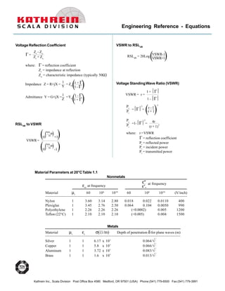
Engineering Reference - Equations
where: Γ = reflection coefficient
Zr
= impedance at reflection
Zo
= characteristic impedance (typically 50Ω)
Voltage Reflection Coefficient
Γ =
Zr
- Zo
Zr
+ Zo
Admittance Y = G±jX = 1 - Γ
1 + Γ( )1
Z
=Y0
Impedance Z = R±jX = 1 + Γ
1 - Γ( )1
Y
= Z0
VSWR to RSLdB
RSLdB
= 20Log( )VSWR-1
VSWR+1
where: r =VSWR
Γ = reflection coefficient
Pr
= reflected power
Pi
= incident power
Pt
= transmitted power
Voltage StandingWave Ratio (VSWR)
r =
1 + Γ
1 - Γ
VSWR =
Pr
Pi
=Γ
2
= r - 1
r + 1( )
2
Pt
Pi
=1-Γ
2
= 4r
(r + 1)
2
εr, at frequency ε′,
Material µr
60 106
1010
60 106
1010
(V/inch)
Nylon 1 3.60 3.14 2.80 0.018 0.022 0.0110 400
Plexiglas 1 3.45 2.76 2.50 0.064 0.104 0.0050 990
Polyethylene 1 2.26 2.26 2.26 (<0.0002) 0.005 1200
Teflon (22°C) 1 2.10 2.10 2.10 (<0.005) 0.004 1500
Material µr
εr
σ( /m) Depth of penetration δ for plane waves (m)
Silver 1 1 6.17 x 10⁷
0.064/√f
Copper 1 1 5.8 x 10⁷
0.066/√f
Aluminum 1 1 3.72 x 10⁷
0.083/√f
Brass 1 1 1.6 x 10⁷
0.013/√f
ε″ at frequency
Metals
Nonmetals
Material Parameters at 20°CTable 1.1
RSLdB
to VSWR
VSWR=
( )(RSL
dB
20
+1
)10
( )(RSL
dB
20
-1
)10
2. Kathrein Inc., Scala Division Post Office Box 4580 Medford, OR 97501 (USA) Phone:(541) 779-6500 Fax:(541) 779-3991
All specifications are subject to change without notice
Engineering Reference - Equations
where: µo
= free space permeability
= 4.0π x 10-7
(H/m)
εo
= free space permitivity
= (F/m)
Characteristic Impedance of Free Space
(10
−9
36π)
ηo
=
µo
εo√ = 120πΩ = 377Ω
where: εr
is relative dielectric from Table 1.1
c = õo
εo
= propagation velocity = 2.997925 x 10⁸
m/s
(≅ 3 x 10⁸
m/s)
In free space the wavelength is:
For a nonmagnetic dielectric:
1
c
fλ =
c
f √εr
λd
= =
λo
√εr
where: Pr
= received power
Pt
= transmitted power
R = separation distance
FriisTransmission Equation
= free space loss
Using effective areas
( )Pr
Pt
= λ
4πR
2
Gt
Gr
Pr
Pt
=
Aet
Aer
λ2
R
( )λ
4πR
2
Characteristic Impedance of Coaxial Line
where: a = inner diameter
b = outer diameter
µr
= relative permeability (usually = 1)
εr
= permitivity (dielectric constant)
as given in Table 1.1
b
a
Zo
= 138 log10(b
a) µr
εr√
Effective Aperature Related to Gain of Antenna
G =
4πAem
λ2
Aem
= λ2
4π G
Watts to dBm
dBw = 10 log10
(Power Watts)
dBm = (10 log10
(Power Watts))+30
dBw toWatts
Watts = 10
Milliwatts = 10
(dBw
10 )
(dBw+30
10 )
dBm toWatts
Watts = 10
Milliwatts = 10
(dBm-30
10 )
(dBm
10 )
Voltage Gain/Loss to dB
dB(gain/loss)
= 20Log10
(Gain or Loss)
dBm to Volts/µVolts
Volts = Log10
-1
( )dBm-13
20
µVolts = Log10
-1
( )dBm-107
20
dBw toVolts/µVolts
Volts = Log10
-1
( )dBw-17
20
µVolts = Log10
-1
( )dBw-137
20
3. Kathrein Inc., Scala Division Post Office Box 4580 Medford, OR 97501 (USA) Phone:(541) 779-6500 Fax:(541) 779-3991
All specifications are subject to change without notice
QuarterWave Matching
Z = √Zo
ZL
where: Z = line impedance
Zo
= desired input impedance
ZL
= given load impedance
Engineering Reference - Equations
Noise Factor
F =
( )Pno
GA
Pni
=
SNRIN
SNROUT
=
Te
To
-1
NF = 10LogF
Noise Figure
F = F1
+
Cascade Noise Factor
F2
-1
GA1
F3
-1
GA1
GA1
+ +…
Freespace Path Loss
L = 96.6 + 20 log(d) + 20 log(f)
where: L = freespace path loss
d = distance in miles
f = frequency in GHz
Directive Antenna Gain
where: G = directive antenna gain
θ = horizontal beamwidth
φ = vertical beamwidth
41253
θ . φ
theoretical
G= 32400
θ . φ
corrected for efficiencies
G=
Radio Horizon (in miles)
H = √2 (Tx)½
(Rx)½
where: H = horizon
Tx = transmit height in feet
Rx = receive height in feet
(
Gain of Parabolic Antenna
where: G = parabolic antenna gain
K = eff L 55%
D = diameter in feet
λ = wavelength in feet
πD
λ
G = 10 logK )
2
Beamwidth of Parabolic Antenna
where: Ψ = beamwidth
D = diameter in feet
λ = feet
70λ
D
Ψ =
4. Kathrein Inc., Scala Division Post Office Box 4580 Medford, OR 97501 (USA) Phone:(541) 779-6500 Fax:(541) 779-3991
All specifications are subject to change without notice
Engineering Reference - Equations
0 10 20 30 40 50 60 70 80 90
-10
-8
-6
-4
-2
0
Scan Angle From Broadside, θ
NormalizedDirectivity,dB
2πL
λ
= 10
2πL
λ
= 100
Cos θ
Reprinted from “Microwave Scanning Antennas”, edited by R. C. Hansen, Vol. 1, p. 20, published by Peninsula Publishing, Los Altos, California.
Courtesy of R. C. Hansen
5. Kathrein Inc., Scala Division Post Office Box 4580 Medford, OR 97501 (USA) Phone:(541) 779-6500 Fax:(541) 779-3991
All specifications are subject to change without notice
Engineering Reference - Equations
10 20 30 40 50
Sidelobe Ratio, dB
BeamBroadening
Taylor one-parameter distribution
Courtesy of Dr. R. C. Hansen
1.1
1.2
1.3
1.4
1.5
1.6
1.7
1.0
Beam BroadeningVersus Sidelobe Ratio