Remote Display MT-5 manual for Tracer1210RN Tracer1215RN Tracer2210RN Tracer2215RN from Ultisolar New Energy
•
1 like•1,914 views

Remote Display MT-5 manual for Tracer1210RN Tracer1215RN Tracer2210RN Tracer2215RN from Ultisolar New Energy Available at http://shop.ultisolar.com

Recommended
Recommended
More Related Content
More from Shandong iSentrol Electronic Technology Co., Ltd
More from Shandong iSentrol Electronic Technology Co., Ltd (20)
Recently uploaded
Recently uploaded (20)
Remote Display MT-5 manual for Tracer1210RN Tracer1215RN Tracer2210RN Tracer2215RN from Ultisolar New Energy
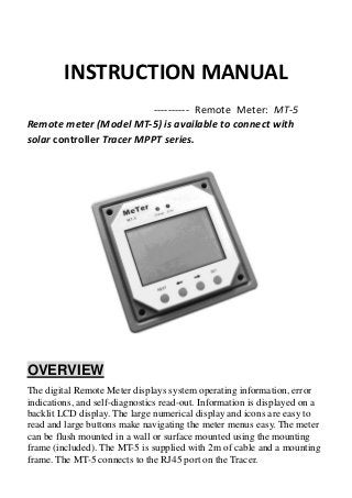
- 1. INSTRUCTION MANUAL ---------- Remote Meter: MT-5 Remote meter (Model MT-5) is available to connect with solar controller Tracer MPPT series. OVERVIEW The digital Remote Meter displays system operating information, error indications, and self-diagnostics read-out. Information is displayed on a backlit LCD display. The large numerical display and icons are easy to read and large buttons make navigating the meter menus easy. The meter can be flush mounted in a wall or surface mounted using the mounting frame (included). The MT-5 is supplied with 2m of cable and a mounting frame. The MT-5 connects to the RJ45 port on the Tracer.
- 2. MECHANICAL DRAWING CONTAINS Wall mounting board, can be mounted in or on the wall with 2 meter cable.
- 3. DISPLAY The two LED indicators above the LCD show that battery is charging, and a red indicates error conditions. The LCD has two different brightness levels. After any button is pressed the display will be in high brightness and backlight. To save power, the backlight automatically turns off after 30 seconds. Error indicator Setting icon Data indicator Battery iconSolar icon Load icon
- 4. OPERATION INSTRUCTION The key from left to right is: K1~K4,or Set, Left( ), Right( ), ESC(Load ON/OFF). 1. The meter display as following order: (Solar panel voltage), (battery voltage, battery current), (load voltage, load current), (battery capacity AH, battery temp.), (battery capacity percentage, temp. compensation), (battery capacity AH, battery type), (Load Timer1 mode, Load Timer2 mode), (discharging accumulation AH, discharging accumulation WH) as eight team data. Use K2, K3, or Left, right key for repeating the data for the team. Data shows as following picture. Remarks: MPPT solar controller is Maximum Power Point tracking technology. So the solar panel charging current may not equals to the sum of battery charging current and load current. is setting icon. It appears in setting status, and disappears in reading status.
- 5. 2. Data setting operation: Reading status, press K1/SET to setting status, press K2, K3 to modify data. K1 for back to reading status and saving data. K4 for back to reading status without saving data. Operation shows as following picture. 3. Data setting instruction Battery capacity modify: capacity modify range from 10AH to 900AH, the default value is 200AH. The modify data should be near or equal to the real capacity. While display battery capacity and temp., press K1 into setting mode, modify the data through K2, K3. Battery capacity will be up/down 10AH, press K1 for saving data and back to the reading status. Or press K4 for back to reading status without saving. The capacity remain the same. Battery temp. compensation: temp. compensation data modify ranges from 0 to 10mV/Cell/℃, while the data is 0, there is no temp. compensation function. While on displaying battery capacity percentage, temp. compensation, press K1 into setting mode, modify the data through K2, K3. The temp. compensation will be up/down 1 mV/Cell/℃.
- 6. Battery type: battery type has three options: SEL-sealed battery, GEL- gel battery, FLD- flooded battery. While on displaying battery capacity and battery type, press K1 into setting mode, choosing suitable battery type through K2, K3. Load mode: load has two timers: Timer1 and Timer2. While on displaying timer1 and timer2, press K1 into setting mode, choosing expected work mode through K2, K3, press K4 to exit setting mode. When load mode is manual, load can be changed to ON or OFF by pressing K4 button on any display surface. Please refer to the controller user’s manual for more information. 4. Other operation: The controller will delete the data automatically while accumulation is over 999. 24-hour data will begin to be accumulated at the moment when solar panel voltage is over 8V for the first time.
- 7. OTHER INSTRUCTION Error icon instruction: Red flashing on error status. Please check the load connection, press K4 for delete error icon. 1. When load current over 1.25 times and less than 1.5 times of rated current, load will be off automatically after 60 seconds. 2. When load current over 1.5 times of rated current but less than short circuit, load will be off automatically after 5 seconds. 3. When load current over short circuit, short circuit protection shut the load. LED indicator: Green on when solar is charging battery, green off without charging. Yellow on when there is error. Yellow off in normal status. Telecommunication port: While the meter run by individual power or the communication cut off, it displays graphical symbols. Press key, no answer. The display will resume while communications is on. Note: the data displayed got from the communication, check if the cable correct while the data is error, or if there is strong interference. Too long cable may bring mistakes too. Battery capacity strip flash: Each strip equals to 20% of battery capacity. Note: the calculation takes fully charged voltage as 100%, and over discharge as 0%. All is based on battery voltage, not the real battery capacity.
- 8. Data updating: Serial communication happens every 10 seconds between control module and display module, so the data update takes in 10-20 seconds. Battery capacity AH: AH is the accumulation of charging, each one minute will count. The data is not accurate while the charge current is too small. The min. is 0.1AH. Charging and discharging accumulation WH: Solar panel displaying is open circuit voltage. It can’t be calculated. WH is product of battery voltage and charging current accumulation. PARAMETERS Remote meter LCD specification Working current Backlight and LED indicator off < 15mA Work temperature -10℃ to +40℃ Communication port RJ45(8PIN) Communication cable 2 meters with supplied cable