1. Vijay Badireddi
Current Transformer Concepts:
(A) Introduction:
Function of a CT is to produce a proportional current suitable for operation of protective device.
Note: 100/ 5 means à 100 A in primary, results in 5 A in secondary (with a condition correct rated
burden is connected).
Now, 100/ 5 is not the same as 20/1 or 10/0.5 CT.
Accuracy CL:
1. Measured current deviated from calculated value.
2. Also, permissible phase angle displacement between primary & secondary currents.
Desirable Characteristics:
1. Measuring CT: Should saturate at 120% or 125% of primary current, i.e, ‘Is’ and ‘Ip’ are in
proportional, until the saturation point ( meeting the accuracy CL requirement), beyond
which ‘Is’ not anymore proportional to ‘Ip’.
Reason: At the saturation point, secondary current is less than proportionate, which occurs
through heavy fault condition. Hence, protecting the measuring device connected to CT
from overload.
2. Protection CT: Reverse to the measuring CT.
ALF: ‘Is’ proportional to the ‘Ip’, when it is ‘several times’ the rated current. That ‘several
times’ is the ALF.
Ex: ALF of 10 à’ Is’ proportional to ‘Ip’, upto 10 times the rated primary current.
Burden:
CT secondary ‘Vo’ increases, with increase in burden & vice versa.
Reason: This is inherent, to maintain current to correct magnitude.
Theoretically: Burden is infinite when the secondary is O.C or high resistance connected and an
infinite H.V appears across the secondary terminals.
Technically Speaking: The voltage is not infinitely high, but high enough to cause breakdown in the
insulation between primary and secondary windings.
Note: Burden includes connected load, resistance of cable and CT.
Assessing adequate CT burden:
Assume, resistance of cable and CT resistance as 0.2 Ω for 5 A CT.
VA= 5VA
This burden should be included into the connected load to determine the actual CT burden.
What happens, if the rated burden is exceeded?
The secondary current is not any more proportional to the primary current, thus driving CT into
saturation.
Importance of low CT resistance: Since, CT resistance is a function of burden, during heavy through
fault condition the burden rises quickly driving CT into saturation.
2. Vijay Badireddi
Phase Shift Error: It is ignored for the current measurement, as it measures the magnitude.
But, for the measuring device like wattmeter, energy meter shows the effect of phase shift.
Ex: At ‘UPF’ phase shift error is almost negligible. But at ‘ZPF’ all the real power (watts) measured is
because of phase shift error (technically, true power is zero).
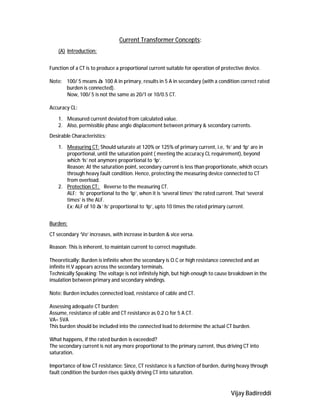
Ip Composite error
Ie
Is
Is
Phase angle error
Knee Point Voltage:
Note: Important characteristic for Diff & REF protection.
Def: The point on the excitation curve where the tangent is 45 ⁰ to the abscissa beyond which CT
becomes non-linear, ie., ‘Is’ is no longer influenced by the primary currents.
3. Vijay Badireddi
To avoid saturation, the CT should develop adequate voltage.
Vk > If (RCT + 2RL+ RB)
Transient Saturation: (Phenomenon of saturation)
Decaying D.C waveform in the primary currents causes the CT, driving into saturation producing
distorted waveform.
Steady state (S.S) conditions are restored once the transients are vanished.
How and why D.C transient occur in the power system? And its effects on the CT.
During the fault conditions, it is expected that the current should follow the ‘Ohms’ law i.e., S.S
phasor relationship.
I = V/Z.
Condition 1: Assume a pure inductance circuit. In pure inductance, I lags V by 90⁰, and
V
I
if the fault occurs at maximum wave point as shown below:
Since, the current is earlier zero, world rise from zero value and hence no transients are to be
expected.
4. Vijay Badireddi
Condition 2: If fault at zero point of voltage as shown below:
The S.S waveform indicates, the fault current should be at maximum value when the fault occur.
This is impossible because the inductance in power system will not allow an instantaneous change
from current zero level prior to fault to a higher value just after the incidence of fault.
(B) Transient behaviour of CT:
1. CTs are designed to transfer A.C
2. There is a situation of translating D.C from primary to secondary due to the inductance in
the power system.
3. CTs are magnetically coupled and voltage induced on secondary is proportional to dФ/dt.
For inductive circuits, it includes
Inductance is combination of DC as well as AC waveform and in practical conditions DC component is
not sustained but decays with system time constant ( Ƭ= L/R).
Shows below the components of currents in an inductive circuit with maximum DC transients:
Asymmetrical faults may generate DC components contributing to CT saturation and the flux
increases with increase in D.C Component, as explained below:
A basic principle of electromechanical conversion is that the output on the secondary is
related to the variation of the coupled magnetic flux.
5. Vijay Badireddi
Even if, D.C current is not converted into secondary current, it does generates magnetic flux
and thus contribute to core saturation. Theoretically speaking, a core fully saturated by a DC current
has no output (as D.C causes no variation of coupled magnetic flux with time).
Note: No instantaneous change in current prior to and after the incidence of fault.
Variation of flux when AC waveform is involved and saturation limits were not reached.
The excursion of the flux involves in the increasing and decreasing flux as well:
Variation of flux when DC offset transient waveform is involved and the integration of
unidirectional DC waveform causes the excursion of flux in the increasing direction only.
6. Vijay Badireddi
Therefore, it can be shown that the CT shall have enough capacity to develop the below voltage not
to saturate at all for a combination of AC & DC transient.
Vs > If (1+X/R) (RCT +RL + RB).
Sizing:
1. Increase the CT tap, result in higher saturation voltage, lower secondary fault current.
2. Reduce the distance between relay & CT
3. Reduce the connected burden.
4. Allow the CT to saturate beyond the relay operating time.