IRJET- Design and Development of Jig and Fixture for Tacho Bracket
FINAL VIVA PRESENTATION (2012250023)
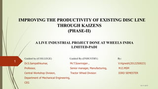
1. Guided by:(COLLEGE) Guided By:(INDUSTRY) By:
Dr.S.Sampathkumar, Mr.T.Sowrirajan , V.Vignesh(2012250023)
Professor, Senior manager, Manufacturing, M.E.MSM
Central Workshop Division, Tractor Wheel Division IIIRD SEMESTER
Department of Mechanical Engineering,
CEG
16-11-2015
1
IMPROVING THE PRODUCTIVITY OF EXISTING DISC LINE
THROUGH KAIZENS
(PHASE-II)
A LIVE INDUSTRIAL PROJECT DONE AT WHEELS INDIA
LIMITED-PADI
2. OBJECTIVE
This project mainly focusses on increasing the productivity of disc
produced for tractor wheel section.
It is aimed to improve the production rate to a considerable amount
at a low cost ,such that the demand is met.
The project deals with the implementation of KAIZENS within the
layout (DISC Section of TRACTOR Wheel division) consisting of
various machining processes, so as to improve the productivity.
16-11-2015
2
3. WORK DONE DURING PHASE I
Studied the existing layout.
Identified the problem.
Conducted time study.
Analysed present cycle time using Time study.
Calculated target cycle time.
Identified no of areas for scope of improvement =14.
Categorised Kaizens according to the priority level.
Conducted brain storming sessions.
Found the conceptual ideas for higher priority Kaizens.
Evaluated each conceptual idea.
4. PHASE II WORK METHODOLOGY
Selected Concept through qualitative analysis
Design of the selected concept
Part and Assembly drawing
Fabrication
Installation
Feedback
Conclusion
FOR ALL KAIZENS K.H.1-K.H.5
5. CHART REPRESENTING THE
OPERATION TIME AT EACH STATION
0
10
20
30
40
50
60
70
Reaming Boring Chamfering De burring Marking Inspection Despatching
PRESENT CYCLE TIME
=64sec
TARGET CYCLE TIME
=41sec
6. AREAS FOR SCOPE OF IMPROVEMENT
16-11-2015
6
S.NO TASK ID ACTIVITY KAIZEN
NEEDED
KAIZEN
NUMBER
01 A.2
Pushing the disc from lifter to
the machine Y K.L.1
02 A.3 Upstroke of the fixture Y* K.H.1
03 A.5 Down stroke of fixture Y* K.H.1
04 A.6 Cleaning of scrap on the disc Y * K.H.2
05 B.2 Boring Operation Y* K.H.3
06 B.4 Cleaning of scrap Y K.L.2
Y*-HIGHER LEVEL PRIORTY KAIZEN
Y- LOWER PRIORITY KAIZEN
7. 16-11-2015
7
S.NO TASK ID ACTIVITY KAIZEN
NEEDED
KAIZEN
NUMBER
07 C.5
Waits for the lifter to get
free Y K.L.3
08 C.8 Cleans the machine Y K.L.4
09 D.2
Removal of Burrs (inside)
Y* K.H.4
10 D.4
Removal of burrs (outside)
Y* K.H.4
11 E.1
Stands and pulls the disc
onto the machine Y* K.H.5
12 E.2
Sets the disc onto the
machine Y* K.H.5
13
E.7
Applying non corrosive
resistant onto the disc
Y* K.H.5
14
E.8
Pushes the disc to next
station
Y* K.H.5
Y*-HIGHER LEVEL PRIORTY KAIZEN
Y- LOWER PRIORITY KAIZEN
8. CONCEPTUAL IDEAS FOR KAIZEN K.H.1-REAMING
STATION
16-11-2015
8
POSSIBLE IDEAS FOR
KAIZEN K.H.1
Decreasing
the bore
diameter of
the cylinder
Decreasing
the stroke
length of the
cylinder
Decreasing
the weight of
the fixture
Fig 3.Reaming station
9. SELECTED CONCEPT FOR KAIZEN
K.H.1
Decreasing the Bore Diameter of the Cylinder:
Earlier the weight of the disc was 55kg(max),so higher bore diameter was needed
to lift the higher load.
But now the disc weight is 34kg(max),so cylinder of relatively lesser bore diameter
is feasible to be replaced.
A lesser bore diameter cylinder can traverse the load with faster rate.
So we can expect time saved by 6 seconds at least.
Existing borediamter of the cylinder=160mm.
10. CYLINDER SPECIFICATION
S.NO CATEGORY DATA
01 MAKE FESTO
02 BORE DIAMETER 80
03 TYPE DNC
04 STROKE LENGTH 150mm
05 STROKE TYPE BOTH FORWARD AND REVERSE
06 SPECIAL THREAD ON
PISTON
YES (PLUS A FEMALE THREAD)
14. 16-11-2015
14
TASK ID ELEMENT NAME VA/NVA BASIC TIME
E.1
Stands and pulls the disc onto the
machine NVA
5.2
E.2 Sets the disc onto the machine NVA(PT) 3.5
E.3 Down stroke of the machine NVA(PT) 2.9
E.4 Marking operation (machining) VA 17.6
E.5 Upstroke of the machine NVA(PT) 2
E.6 Lifting of the disc NVA(PT) 2
E.7
Applying non corrosive resistant onto
the disc NVA 12.5
E.8 Pushes the disc to next station NVA(PT) 2.2
ELEMENTAL TIME AT MARKING STATION
15. CONCEPTUAL IDEA FOR KAIZEN AT
MARKING STATION
This station constites more proportion of non value adding activity due to present
technology.
They are very tough to remove separately as one activity links to the other.
The company feels the use of labor force to such a simple activity is not cost
effective.
IDEA
Automating the entire marking station .
16-11-2015
15
16. CORE OBJECTIVES OF THE NEW
MACHINE
There are six core objectives of the new machine. Those are:
Marking of wheels India logo and the part number on the corresponding disc.
Elimination of human work on the marking workstation.
Flexible to mark both inside and outside of the part, as accordingly.
Reducing the non-value adding activity at the workstation.
Reducing the overall labor cost involved in the tractor disc line.
Keeping the payback period to the minimum
17. WHY SIMPLE AUTOMATION??
Cost of variable labour cost increasing day by day.
Scarcity of labour availability.
Other overheads pertaining to the labour.
Savings made from automating the process is high.
Pay back period is minimum for simple automation.
18. OLD SETUP OF THE MARKING
STATION
A roller conveyor is used to transmit the disc from De burring station to the marking
station.
ROLLER
CONVEYOR LIFTER
MARKING
TABLE
19. IDEA GENERATED
A simple idea of replacing the present roller drive mechanism to the
chain drive was generated.
A total number of fixtures was increased to 5 (3 on the top and 2 on
the bottom),such that 3 disc are on the machine at the same time.
A central control panel is made to control the entire automation unit
of the machine (PLANNED BY ELECTRICAL DEPARTMENT).
An automatic lifter was planned to position the disc on the de
burring machine.
20. DETAILS OF CHAIN DRIVE
S.NO DATAS VALUES
01 Type of Chain Bush Roller Chains
02 Material Alloy steel
03 Lubrication Grease
04 No of Teeth on Chain Sprocket 40
05 Designed Power 2.10 Kw
06 Pitch 15.875mm
07 Roller Dia 10.16mm
08 ISO Standard 10B
09 Breaking Load 22.2KN
10 Load on Chain 950N
11 No of Chain Links 140
21. OVERALL MACHINE SPECIFICATION
S.NO DATAS VALUES
1 Length 1850mm
2 Width 510mm
3 Height 840mm
4 Distance between Pedestals 800 mm
5 No of Pedestals 5
6 Type of Drive Chain
7 No of Chains 2
8 No of Sprockets 4
9 Distance between sprockets 1600mm
10 No of Supporting Column 2
22. IMAGE OF THE NEW MACHINE
CHAIN
FIXTURES
(5NOS)
STOPPER
BLOCK
DISC
SUPPORTIN
G COLUMN
CHAIN SPROCKET
=4 NOS
23. COMPARISON OF PRODUCTION ANALYSIS BEFORE AND
AFTER IMPLEMENTATION OF MARKING MACHINE
Avg.Prod Rate (Rp*) = 60/Tp*
= (60/0.85)
Rp* = 70discs/hr (9)
Rp* = 70 * 8
Rp *= 560 discs/shift (10)
DIFFERENCE IN PRODUCTION LEVEL
Rp*-Rp=560-424
= 136 discs/shift
24. ACTUAL COST FOR INSTALLING NEW
MARKING MACHINE
Cost of the new machine = Rs 7,10,000 (CONTRACT MTM)
Cost of lifter assy = Rs 10,000
Cost of forklift used = Rs 1,500
Cost of labour involved = Rs 14*500
= Rs 7,000 per shift
Number of Shift = 2
Total cost of Labour = Rs 14,000
-----------------
TOTAL COST = Rs 7, 35,500 (A)
-----------------
25. ACTUAL SAVINGS ASSOCIATED AFTER INSTALLING NEW
MACHINE
Annual Labourcost = Rs2, 50,000 P.afor one labour.
Number oflabourwork saved = 2 (One laboureachshift)
Total Annual Labourcost Saved = Rs 5,00,000 P.a (B)
26. PAY BACK ANALYSIS
Pay Back Period = (Initial Investment of the machine)
-------------------------------------------
(Annual Savings)
Payback Period = (Rs 7, 35,500)/ (Rs 5, 00,000)
= 1.471 Years
= 1 Year 6 months.
Thus the new marking machine has a Payback Period of 1 Year and 6 months.
27. DE BURRING OERATION
This operation is done to
remove burrs that are stucked
on the outside portion of the
holes.
It helps in producing a better
surface finish.
The specification of wheel
presently is:
16-11-2015
27
MAKE PROFORMER
GRIT SIZE 80
MAX RPM 15280
SPEED OF
REMOVAL 80
28. 16-11-2015
28
QUALITATIVE RATINGS FOR THE
ALTERNATIVESIDEA
NO
IDEA COS
T
TIME EASE OF
CHANGE
LEVEL OF
IMPROVEMENT
K.H.4.1 Changing the grit
size 4 4 4 12
K.H.4.2 Increasing the
wheel diameter
3 3 3 9
K.H.4.3 Changing the
wheel material
2 3 4 9
K.H.4.4 Increasing the
no of spindles
4 4 4 12
K.H.4.5 Automating the
process
2 2 2 6
RATINGS DONE FROM 1 TO 5
SCALE…
1>>>POOR SOLUTION
29. FEATURES OF MULTIHEAD SPINDLE
By using the multihead de burring head, the productivity is improved.
Time for one hole deburring is the time for multiple hole deburring.
Multi spindle can be a fixed centre for construction and for batch production.
MASTER GEAR
SUPPORTING COLUMN
MULTI DEBURRING
HEAD
30. PARTS IN MULTI HEAD DEBURRING
MACHINE
DRIVE MOTOR
MASTER GEAR
SUPPORTING COLUMN
MULTI
DEBURRING
HEAD
31. SPECIFICATION OF MULTIHEAD DEBURRING
MACHINE
S.NO CRITERIA VALUES
01 NO of Spindles 3
02 Indexing Yes
03 Pitch 160mm
04 Length of column 1850mm
05 Width of the base 1675mm
06 No of Supporting Gear 4
07 Maximum Speed of Spindle
rotation
450rpm
08 Name of the Supplier Tool Tek Special Machines-Pune
09 Warranty 12months
32. BORING OPERATION
Boring is the machining
process, where internal surface
of revolution are created by
single point cutting tool.
In here, the central hole is
bored.
The hole is enlarged by 10 %
of the blanked size.
In order to achieve greater
accuracy ,this operation is
done.
In some disc, its done as there
is a non availability of drill bits
on a standard scale.
16-11-2015
32
Hole to be
bored
33. CONCEPTUAL IDEAS FOR KAIZEN 3(K.H.3)
FOR ACTIVITY(B.2) AT BORING STATION
At present the cutting tool is Carbide steel material.
Speed ,Feed, Depth of cut are varied according to the disc variety.
A hydraulic cylinder helps in actuating the cutting tool up and down. .
IDEAS GAINED FROM BRAIN STORMING
K.H.3.1Increasing the hydraulic fluid pressure from 4 bar to 5bar.
K.H.3.2 Changing the essential parameters for MRR
(Speed,Feed,Depth of cut).
K.H.3.3Changing the tool material.
K.H.3.4Reducing the percentage of enlargement from forming.
16-11-2015
33
34. 16-11-2015
34
POSSIBLE IDEAS FOR
KAIZEN K.H.3
Reducing the
enlargement
percentage
Changing
the
parameters
of MRR
Increasing
the pressure
Changing
the tool
material
BRANCH OF IDEAS FOR KAIZEN K.H.3
35. 16-11-2015
35
IDEA NO IDEA COS
T
TIME EASE OF
CHANGE
LEVEL OF
IMPROVEMENT
K.H.3.1 Changing the
parameters of
MRR
4 4 4 12
K.H.3.2 Changing the tool
material
2 4 4 10
K.H.3.3 Reducing the
enlargement
percentage
2 2 2 6
K.H.3.4 Increasing the
pressure
3 4 4 11
QUALITATIVE RATINGS FOR THE ALTERNATIVES
RATINGS DONE FROM 1 TO 5
SCALE…
1>>>POOR SOLUTION
5>>>BEST SOLUTION
38. S.NO CRITERIA BEFORE ESTIMATED AFTER
01 Batch Processing Time 360mins 225mins 255mins
02 Average Production
Time
1.2Mins/Disc 0.75Mins/Disc 0.85Mins/Disc
03 Average Production
Rate
50Disc/Hr 80Disc/Hr 70Disc/Hr
04 Production Level 400Discs/Shift 650Disc/Shift 560Disc/Hr
05 Cycle Time 1.05Mins/Disc 0.36Mins/Disc 0.7Mins/Disc
06 No of labours Involved 07 05 06
07 No of station 07 07 07
08 No of automated
Station
0 02 01
09 No of Manual Station 07 05 06
10 Labour cost Involved Rs 35,00,000 Rs 25,00,000 Rs 30,00,000
11 Annual Production
Level
2,17,200 3,60,000 2,80,000
PRODUCTION LINE CHARACTERSTICS BEFORE, ESTIMATED
AND AFTER KAIZENS
39. SUMMARY –PHASE 2 WORK
1. Selected Concept through qualitative analysis
2. Designed the selected concept
3. Part and Assembly drawing drawn
4. Fabricated or Purchased
5. Installed
6. Feedback
7. Conclusion
PHASE 2
WORK
40. FUTURE SCOPE OF WORK
1. Installation of Multihead deburring spindle for the KAIZEN K.H.4.
2. Studying of Results for the Kaizen K.H.4.
3. Feedback for the Kaizen K.H.4.
4. Performing the experiments for various input parameters (Speed, Feed, and
Depth of Cut) for increasing MRR for Boring operation (KAIZEN K.H.3).
5. Performing Design of experiments to find the optimized MRR.
6. Changing the existing parameters to the optimised input parameters found
through DOE.
7. Studying the results and feedback for KAIZEN K.H.3.
8. Increasing the velocity of the cutting fluid.
9. Solving Lower Priority Kaizens one by one.