Comparison between Rectangular and Circular Patch Antennas Array
icwet-ppr
1. International Journal of Computer Applications (0975 – 8887)
Volume *– No.*, ___________ 2011
Structural Modification and Size Reduction of
Folded Dipole Antenna by Fractal Technique
Nidhi G Sharma
nidhs_13@gmail.com
Nikhil Verma
nikhilverma1990@gmail.
com
Venkatakrishnan
Vaidyanathan
Nishit Shetty
nishit_0047@yahoo.com
venkatvaidya25@gmail.com
ABSTRACT
This paper aims at designing a new structural orientation for the
existing folded dipole antenna to make it compatible with loop
antenna for producing circularly polarized wave without
bringing any change in the feed line through the loop.Fractal
technique is used to achieve the physical size reduction of the
folded dipole antenna. The simulations carried out using
Numeric Electromagnetic Code (NEC) reveal that the fractalized
folded dipole antenna can be used as a substitute of the
conventional dipole especially for the narrow band of operation.
Also the simulated results for structurally modified folded dipole
antenna and conventional dipole are same implying that the
modified structure can replace the existing one.
General Terms
RF and Microwave Devices
Keywords
NEC, Fractal Technique, Bandwidth
INTRODUCTION
To interface the folded dipole antenna with loop antenna for
circularly polarized wave generation following structural
modification is used(fig.1).As a result without bringing any
change in the feed line through the loop, direct interfacing of the
two can be achieved.
Figure 1: Structural modification of folded dipole
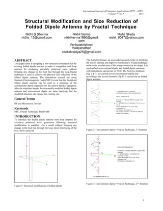
The fractal technique, an area under research, helps in shrinking
the size of antenna and improve its efficiency. Fractal technique
reduces the area because of the many contours in the shape. It is
used on both conventional dipole and folded dipole antennas
with simulations carried out on NEC. The first two iterations
(fig. 2 & 3) are carried out on conventional dipole and
accordingly the second iteration (fig.4) is carried out on folded
dipole antenna.
Figure 2: Conventional dipole –Fractal Technique, 1st
Iteration
Figure 3: Conventional dipole –Fractal Technique, 2nd
Iteration
1
2. International Journal of Computer Applications (0975 – 8887)
Volume *– No.*, ___________ 2011
Figure 4: Folded dipole-Fractal technique, 2nd
Iteration
Thus the above figure shows the transition from conventional
structure to 2nd iteration Fractal Folded Dipole Antenna.
SIMULATIONS
We have divided the simulations into two parts; one depicting
structurally modified folded dipole antenna with a spacing of
3mm and 5 mm and the other showing simulated results of the
fractalized folded dipole antenna.
Structurally modified folded dipole antenna
with a spacing of 3mm and 5 mm
Gap of 5mm between the elements
Figure 5: Standing wave ratio and Reflection coefficient
Figure 6: Gain (Vertical Plane)
Gap of 3mm between the elements
Figure 7: Standing wave ratio and Reflection coefficient
Figure 8: Gain (Vertical Plane)
2
3. International Journal of Computer Applications (0975 – 8887)
Volume *– No.*, ___________ 2011
Fractal technique for Folded Dipole Antenna
Figure 9: Standing wave ratio and Reflection coefficient
Figure 10: Gain (Vertical Plane)
Figure 11: Smith Chart
CONCLUSIONS
Simulated results show that for structurally modified dipole
antenna as the spacing between the elements reduces, the
bandwidth of the antenna increases. The Fractal Technique
implemented shows that the performance of the fractalized
folded dipole is same as that of the conventional with an
advantage of reduction in size. However, this is achieved at the
cost of bandwidth and hence can be used to replace the
conventional one for narrow band applications.
ACKNOWLEDGMENTS
Our thanks to Prof. Shailendra Shastri for constant support,
guidance, co-ordination and encouragement which helped us
overcome all possible hurdles that came our way.
REFERENCES
ANTENNA- John D. Krauss ,Tata Mc Graw Hill, 2nd
Edition
THE KOCH MONOPOLE: A SMALL FRACTAL ANTENNA
BANDWIDTH –ENHANCED ELECTRICALLY SMALL
PRINTED FOLDED DIPOLES- Yanyan Zhang and H.Y. David
Yang, Fellow , IEEE
3