
Recommended
More Related Content
What's hot
What's hot (17)
Similar to 2004 6.0 l f error de arranque
Similar to 2004 6.0 l f error de arranque (20)
Recently uploaded
Recently uploaded (20)
2004 6.0 l f error de arranque
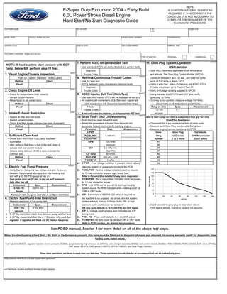
- 1. CUSTOMER NAME DEALER NAME P & A CODE ODOMETER MODEL YEAR VEHICLE SERIAL N0.(VIN) ENGINE SERIAL NUMBER TRANSMISSION CHASSIS STYLE VEHICLE GVW 1863 CLAIM NUMBER AMBIENT TEMP. DATE CUSTOMER CONCERNS (Please list in this box) TYPE OF SERVICE PERSONAL COMMERCIAL 7. Perform KOEO On-Demand Self Test 11. Glow Plug System Operation • Use scan tool. DTC's set during this test are current faults GPCM Operation Diagnostic • Glow Plug ON time is dependent on oil temperature 1. Visual Engine/Chassis Inspection Trouble Codes and altitude. The Glow Plug Control Module (GPCM) Fuel Oil Coolant Electrical Hoses Leaks 8. Retrieve Continuous Trouble Codes comes on between 1 and 120 sec., and does not come Method Check • Use the scan tool. on at all if oil temp is above 131 F. Visual • DTC's retrieved during this test are historical faults. • Using a scan tool , check Continuous and KOEO DTC's. Diagnostic If codes are present go to Pinpoint Test AF. 2. Check Engine Oil Level Trouble Codes • Verify B+ voltage is being supplied to GPCM. • Check for contaminants (fuel, coolant). 9. KOEO Injector Self Test (Click Test) • Using the scan tool GPCTM and EOT pids, verify • Correct Grade/Viscosity. • Use scan tool. Injector DTC's will be displayed at test end. glow plug "on" time . • Miles/Hours on oil ,correct level. • All injectors will momentarily click, then each injector will • Turn key to run position, measure voltage ("on"time) Method Check (Dependent on oil temperature and altitude) Visual Injector Relay on time Spec. Measurement Trouble Codes 1 to 120 B + 3. Intake/Exhaust Restriction » If self test codes are retrieved, go to appropriate PPT test. seconds • Inspect air filter and inlet ducts. 10. Scan Tool - Data List Monitoring Wait to Start Lamp "on" time is independent from g/p "on" time • Inspect exhaust system. • Scan tool may reset below 9.5 volts. Glow Plug Resistance • Check if air filter minder indicator has been illuminated • Select the parameters indicated from the scan tool • Disconnect the 4-pin connector at front of valve cover Method Check parameter list and monitor while cranking engine. • Measure each Glow Plug resistance to Bat. ground. Visual Parameter Spec. Measurement • Measure engine harness resistance to GPCM V PWR Glow Glow Plug Harness to 4. Sufficient Clean Fuel FICMLPWR 8 volt min. Plug to Ground GPCM connector • Check if the WATER IN FUEL lamp has been FICMVPWR Number .1 to 2 ohms 0 to 1 ohms illuminated. RPM 100 RPM #1 • After verifying that there is fuel in the tank, drain a minimum #3 sample from fuel control module. ICP 3.5 mPa min. #5 • Cetane rating between 40-50 is recommended for (500 PSI) #7 optimum start. ICP volts .80 V min. #2 Method Check FUEL PW 500 uS - 2 mS #4 Visual FICMSYNC Yes/No #6 A - V PWR - If low voltage condition is present, check battery, #8 5. Electric Fuel Pump Pressure charging system, or power/gnd circuits to the PCM. • Verify that the fuel pump has voltage and gnd. At key on. B - FICMLPWR - No/low voltage indicated could be caused • Measure fuel pressure at engine fuel filter housing test by 12-way connector issue or logic power fuse. port with a (0-160 PSI) gauge at key on. Refer to Pinpoint S for detailed 12-way conn. diagnostics Fuel pump runs for 20 sec. at key on and pressure C - FICMVPWR - No or low voltage indicated could be caused falls after key off. by 12-way connector issues. Instrument Spec. Measurement D - RPM - Low RPM can be caused by starting/charging 0-160 PSI 45 PSI min. system issues. No RPM indicated while cranking could be Gauge CMP or CKP faults. If pressure fails low go to next step to verify no restriction E - ICP - A minimum of 500 PSI (3.5 mPa) is required for 6. Electric Fuel Pump Inlet Restriction the injectors to be enabled. No or low oil in the system, • Measure restriction at fuel pump inlet. system leakage, injector O-Rings, faulty IPR, or high Instrument Spec. Measurement pressure pump could cause low pressure. • Add 5 seconds to glow plug on time when above 0-30 " Hg 6" Hg MAX IPR duty cycle defaults to 14 % (300 PSI) w/o CKP signal. 7000 feet in altitude, but not to exceed 120 seconds. vacuum F - ICP V - Voltage reading below spec indicates low ICP » If > 6" Hg restriction, check lines between pump and fuel tank. during crank. » If < 6" Hg, inspect both fuel filters. If filters are OK, check fuel G - FUEL PW - Pulse width defaults to 0 w/o CKP signal regulator. If regulator and filters are OK, replace fuel pump. H - FICMSYNC- No sync could be caused CMP or CKP faults. » Refer to PC/ED section 4 for detailed test procedures. What problems were found and what repairs were performed? List Part Name, Number and Serial Number of parts replaced. Some labor operations are listed in more than one test step. Those operations include time for all occurrences and can be claimed only once. click in sequence 1-8. Sequence repeats three times. See PC/ED manual, Section 4 for more detail on all of the above test steps. When troubleshooting a Hard Start / No Start or Performance concern, this form must be filled out to the point of repair and returned, to receive warranty credit for diagnostic time for the parts listed below. Fuel Injectors (9E527), regulator-injection control pressure (9C968), pump assembly-high pressure oil (9A543), turbo charger assembly (6K682), fuel control module (9G282), FICM (12B599), PCM (12A650), EGR valve (9P452), CKP sensor (6C315), CMP sensor (12K073), GPCM (12B533), and Glow Plugs (12A342). -NOTE- IF CONCERN IS FOUND, SERVICE AS REQUIRED. IF THIS CORRECTS THE CONDITION, IT IS NOT NECESSARY TO COMPLETE THE REMAINDER OF THE DIAGNOSTIC PROCEDURE. NOTE: A hard start/no start concern with EOT Temp. below 60F perform step 11 first. F-Super Duty/Excursion 2004 - Early Build 6.0L Power Stroke Diesel Engine Hard Start/No Start Diagnostic Guide 6005E 6005E6 6005E 6005E 6005E7 6005E8 6005E4 6005E3 6005E2 6005E5 0 20 40 60 80 100 120 140 0 20 40 60 80 100 120 140 EOT (F) Time(seconds) 6005E3