1. US 20070119495A1
(19) United States
(12) Patent Application Publication (10) Pub. No.: US 2007/0119495 A1
Sumrall (43) Pub. Date: May 31, 2007
(54) SYSTEMS AND METHODS FOR Related US. Application Data
GENERATING ELECTRICITY USING A
THERMOELECTRIC GENERATOR AND (60) Provisional application No. 60/740,004, ?led on Nov.
BODY OF WATER 28, 2005
Publication Classi?cation
(75) Inventor: Theodore S. Sumrall, Fort Walton (51) Int CL
Beach’ FL (Us) H01L 35/30 (2006.01)
H01L 35/28 (2006.01)
(52) US. Cl. .......................................... .. 136/205; 136/224
Correspondence Address:
SUTHERLAND ASBILL & BRENNAN LLP (57) ABSTRACT
999 PEACHTREE STREET, N.E. _ _ _
ATLANTA, GA 30309 (Us) A system for producing electrical poWer a thermoelectric
generator including a thermopile, a hot junction, and a cold
junction. A high temperature source may be thermally
(73) Assignee: Theodore Sheldon Sumrall Trust, a Coupled to the hot junction wherein the high t?mp?ramre
Living Revocable Trust’ Fort Walton source includes heat from Within the earth’s surface. A loW
Beach, FL temperature source may be thermally coupled to the cold
junction Wherein the loW temperature source comprises cold
(21) App1_No,; 11/539,749 Water from a body of Water. The thermopile generates
electricity from a temperature gradient between the hot
1e : ct. , unct1on an t e co unct1on.22 El d O 9 2006 j ' d h ldj '
400
‘N0
450 402
416
8. US 2007/0119495 A1
SYSTEMS AND METHODS FOR GENERATING
ELECTRICITY USING A THERMOELECTRIC
GENERATOR AND BODY OF WATER
RELATED APPLICATION DATA
[0001] The present application also claims priority to US.
Provisional Application No. 60/740,004 entitled “Systems
and Methods for Generating Electricity Using a Thermo
electric Generator” ?led on Nov. 28, 2005, Which is incor
porated herein by reference in its entirety.
GOVERNMENT CONTRACT
[0002] The US. Government has a license in this appli
cation pursuant to Contract Number F08630-03-C-0133
aWarded by the US. Department of Defense.
TECHNICAL FIELD
[0003] This application relates generally to the ?eld of
electricity generation through the use ofheat from Within the
earth’s crust and more particularly to the use of thermoelec
tric generators in combination With heat from Within the
earth’s crust and cool ?uid for electricity generation.
BACKGROUND OF THE APPLICATION
[0004] Conventional systems for generating electricity for
consumption and use by the public include nuclear poWer,
fossil fuel poWered steam generation plants and hydroelec
tric poWer. Operation and maintenance of these systems is
expensive and utiliZes signi?cant natural resources and in
some cases results in excessive pollution, either through
hydrocarbon combustion or spent nuclear fuel rod disposal.
Oil may be considered a non-reneWable source of poWer,
Which leaves non-petroleum producing countries at the
mercy of those Which produce petroleum.
[0005] Nuclear poWer also has its problems. Currently,
nuclear material is mined from the earth, re?ned and then
utiliZed in a nuclear poWer plant. Suf?cient amounts of
Uranium-235 and/or plutonium are con?ned to a small
space, often in the presence of a neutron moderator. The
subsequent reaction produces heat Which is converted to
kinetic energy by means of a steam turbine and then a
generator for electricity production. Nuclear poWer currently
provides about 17% of the United States electricity and 7%
ofglobal energy. The cost for bringing a nuclear poWer plant
on line is approximately $10-30 Billion. An international
effort into the use ofnuclear fusion for poWer is ongoing, but
is not expected to be available in commercially viable form
for several decades.
[0006] Therefore, there is a need in the art for systems and
methods for generating clean electrical poWer cheaply With
out relying upon the import of petroleum materials or
building of multi-billion dollar poWer plants.
DETAILED DESCRIPTION OF THE DRAWINGS
[0007] FIG. 1 is a diagram of the Seebeck Effect for
thermoelectric systems according to an exemplary embodi
ment of the present application.
[0008] FIG. 2 is a thermopile of the thermoelectric system
according to an exemplary embodiment of the present
application.
May 31, 2007
[0009] FIG. 3 is a thermoelectric generator according to an
exemplary embodiment of the present application.
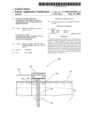
[0010] FIG. 4 is an illustration of a thermoelectric gen
eration system according to an exemplary embodiment of
the present application.
[0011] FIG. 5 is an illustration of temperatures Within the
earth’s surface according to an exemplary embodiment of
the present application.
[0012] FIG. 6 is an illustration of a pipe including an
interior pipe and an exterior pipe according to an embodi
ment of the present application.
[0013] FIG. 7 is an illustration of a thermoelectric gen
eration system according to an exemplary embodiment of
the present application.
[0014] FIG. 8 is an illustration of a thermoelectric gen
eration system according to an exemplary embodiment of
the present application.
DETAILED DESCRIPTION OF THE
APPLICATION
[0015] The present application noW Will be described
more fully hereinafter With reference to the accompanying
draWings, in Which an exemplary embodiment of the appli
cation is shoWn. This application may, hoWever, be embod
ied in many different forms and should not be construed as
limited to the embodiments set forth herein; rather, this
embodiment is provided so that this disclosure Will be
thorough and Will fully convey the scope of the application
to those skilled in the art. Like numbers refer to like
elements throughout.
[0016] As illustrated in FIG. 1, continuously ?oWing elec
trical current may be created When a ?rst Wire 12 of a ?rst
material is joined With a second Wire 14 ofa second material
and then heated at one ofthejunction ends 16. This is knoWn
as the Seebeck Effect. The Seebeck effect has tWo main
applications: Temperature Measurement (thermocouple) and
PoWer Generation. A thermoelectric system is one that
operates on a circuit that incorporates both thermal and
electrical effects to convert heat energy into electrical energy
or electrical energy to a decreasing temperature gradient.
The combination of the tWo or more Wires creates a ther
mopile 10 that is integrated into a thermoelectric system.
When employed for the purposes of poWer generation, the
voltage generated is a function of the temperature difference
and the materials of the tWo Wires used. A thermoelectric
generator has a poWer cycle closely related to a heat engine
cycle With electrons serving as the Working ?uid and can be
employed as poWer generators. Heat is transferred from a
high temperature source to a hot junction and then rejected
to a loW temperature sink from a cold junction or directly to
the atmosphere. A temperature gradient betWeen the tem
peratures ofthe hot junction and the cold junction generates
a voltage potential and the generation of electrical poWer.
Semi-conductors may be used to signi?cantly increase the
voltage output of thermoelectric generators.
[0017] FIG. 2 illustrates a thermopile 20 constructed With
a n-typed semiconductor material 22 and a p-type semicon
ductor material 24. For increased electrical current, the
n-type materials 22 are heavily doped to create excess
electrons, While p-type materials 24 are used to create a
de?ciency of electrons.
9. US 2007/0119495 A1
[0018] Thermoelectric generator technology is a func
tional, viable and continuous long-term electrical poWer
source. Due to the accessibility of temperature gradients
occurring in natural and man-made environments, thermo
electric generators can provide a continuous poWer supply in
the form of electricity. One of the most abundant, common,
and accessible sources of energy is environmental heat,
especially heat contained Within the earth’s crust
[0019] FIG. 3 illustrates an embodiment of the thermo
electric generator. The thermoelectric generator 300 may
include an input 310 to a hot junction 320 and an output 330
to the hot junction 340. The hot junction 320 may include
any source of heat for heat transfer. In an exemplary
embodiment, the source of heat is a hot plate 340. The hot
plate 340 may be metal or any other conductive material.
The hot plate 340 may interface the thermopile 350 to
provide heat to the thermopile through conduction, convec
tion, radiation, or any other heat transfer means. One of
ordinary skill in the art Will appreciate that any thermoelec
tric generator may be used herein and is not limited to this
embodiment. Any system that alloWs the heat to access the
thermopile is contemplated herein.
[0020] The thermoelectric generator 300 may further
include a cold junction 360. The cold junction 360 may
include a cold plate 370 for heat transfer. Alternatively, heat
may be radiated or convected aWay from the cold junction.
The cold plate 370 may be metal or any other conductive
material. The cold plate 370 may interface the thermopile
350 to provide a conductive heat sink. Voltage potential may
be created across the thermopile 350 from a temperature
gradient betWeen the temperature of the hot plate 340 and
the temperature of the cold plate 370. The greater the
temperature gradient, the more electrical poWer may be
generated. One ofordinary skill in the art Will appreciate that
any thermoelectric generator may be used herein and is not
limited to this embodiment.
[0021] Any system that provides a heat sink that interfaces
the thermopile is contemplated herein, including naturally
occurring sources of heat absorption such as a ?uid. In an
exemplary embodiment, the ?uid is Water. Water may be
obtained from any source including an ocean, sea, gulf,
river, stream, creek, lake, spring, or from any underground
source such as underground Wells or from public Water
systems for the purposes of this application. Since the Water
is used to absorb heat, Water from a public Water system used
as the heat sink herein may serve an ancillary purpose of
preheating the Water to decrease the poWer required by the
public, government, or industry to heat the Water for any
desired use. Water or any ?uid as the loW temperature source
provides a technical bene?t over air or gas by having a
higher heat transfer coe?icient and therefore providing bet
ter heat transfer With the cold junction.
[0022] FIG. 4 illustrates an exemplary embodiment of a
thermoelectric generation system 400. Athermoelectric gen
erator may be used in the thermoelectric generation system
to produce electrical poWer from a temperature gradient
betWeen a loW temperature source and a high temperature
source. The thermoelectric generation system 400 may be
located in or near a body of Water 402 including but not
limited to an ocean, gulf, sea, lake, river, spring, creek, or
any other relatively cooler body ofWater. The thermoelectric
generation system 400 utiliZes the body of Water 402 as the
loW temperature source for the thermoelectric generator.
May 31, 2007
[0023] The body of Water 402 can provide signi?cantly
loWer temperatures to the thermoelectric generator to
increase the temperature gradient. In a body of Water 402,
such as an ocean, gulf, sea, or lake, the temperature of the
Water decreases With depth. At a depth commonly referred
to as the thermocline, the Water temperature signi?cantly
decreases. The depth at Which a thermocline occurs averages
betWeen 30 and 50 meters, and varies throughout the World.
It is preferred for the loW temperature source to be Water at
a depth beloW the thermocline to provide a continuous
source of cold Water, and preferably in a current to alloW a
continuous ?oW of cool Water so that the Water is not
stagnant and therefore rises in temperature throughout
energy production operations. Additionally, location of the
poWer plant adjacent to some other surface body of rela
tively cooler Water Will alloW the Water to ?oW through the
plant and then be discharged With minimal thermal change
of the Water.
[0024] The high temperature source may be provided from
Within the earth’s crust 404. The earth provides a continu
ous, inexpensive source of extremely high heat. As illus
trated in FIG. 5, the temperature Within the earth generally
increases toWards the core of the earth at an average rate of
approximately 1 degree Fahrenheit for every 60 feet of
depth. Therefore, locations deep Within the earth may be
used as the high temperature source for the hot junction of
the thermoelectric generator. Locations Within the earth may
be accessed through drilling or other means for creating a
hole 416 in the ground and Water or some other type of heat
transfer medium circulated through the hole and brought to
or near the surface to alloW for heat transfer to occur by the
employment ofhigh e?iciency pumps or some other method.
[0025] Certain holes, commonly referred to as dry holes
may be used to access the high temperatures Within the
earth’s crust. Dry holes typically exist from the unsuccessful
efforts of the petroleum industry to locate oil or gas. The
petroleum industry drills Wells deep into the earth’s crust for
the exploration for petroleum. The overWhelming majority
of exploration Wells drilled throughout the World do not
locate petroleum and are thereby indicated as “dry holes.”
Dry holes provide relatively easy access to the subterranean
levels and high temperature conditions. Dry holes may be
located on land or in a body of Water. Dry holes may reach
depths in excess of 30,000 feet. HoWever, one of ordinary
skill in the art Will appreciate that dry holes may be any
depth. As shoWn in FIG. 5, temperatures in the dry holes can
reach extremely high temperatures. In the exemplary
embodiment of FIG. 5, temperatures in that particular dry
Well are approximately 209 degrees F. at 6100 feet. One of
ordinary skill in the art Will appreciate that this application
is not limited to the use of dry holes and may include any
hole in the earth’s crust Which can provide a heat source
including holes drilled for use by a thermoelectric generator
as Well as expended oil and gas Wells
[0026] Referring again to FIG. 4, the thermoelectric gen
eration system may include a pump station 410, a pipe
system 420, a thermoelectric generator 430, and a ?uid 440.
The thermoelectric generation system may be positioned in
or proximate to a body of Water 402. The pump station 410
may include a pump and associated housing for the pump.
The pump may be any commercially available or specially
designed pump that is capable of forcing ?uid to ?oW at a
suitable volumetric rate. The pump station 410 may be
10. US 2007/0119495 A1
located on land, above the Water surface, or underneath the
Water. The pump station 410 is connected to the pipe system
420. The pipe system 420 includes at least one pipe 422. The
pipe 422 may include an inner bore for carrying ?uid 440 to
be heated by the earth. The inner bore may be any suitable
diameter that alloWs su?icient ?uid 440 to be pumped
through the pipe system. The pipe 422 extends from the
pump station 410 into the hole 416 and may be substantially
U-shaped such that the pipe 422 ascends out of the hole.
[0027] The pipe system 420 may interface a hot junction
320 of the thermoelectric generator 430. The inner bore of
the pipe 422 of the pipe system 420 is accessible to an input
of the hot junction 320 of the thermoelectric generator 430.
The pipe system 420 extends from an output of the hot
junction 320 ofthe thermoelectric generator 430 to return to
the pump station 410.
[0028] In another exemplary embodiment illustrated in
FIG. 6, the pipe system may include an exterior pipe 423 and
an interior pipe 424 such that an annulus 425 exists betWeen
the interior pipe 424 and the exterior pipe 423. In this
exemplary embodiment, the ?uid 440 may be pumped into
the hole through the interior pipe 424, and the ?uid 440
heated by the earth may be pumped out the hole through the
annulus 425 to the hot junction 320 of the thermoelectric
generator 430.
[0029] The ?uid 440 is forced through the pump using the
pump station 410. The ?uid 440 is circulated through the
pipe 422, the hot junction 320 of the thermoelectric genera
tor 430, and the pump station 410 using the pump. Addi
tional ?uid may be added to the pipe system 420 either
continuously or When needed by the system to account for
any loss of ?uid during operation of the pipe system and
pump station. However, one of ordinary skill in the art Will
recogniZe that other methods of bringing the heated ?uid to
or near the surface may be employed.
[0030] The ?uid 440 Within the pipe 422 is heated by the
earth as it descends from the pump station 410 toWards the
bottom of the hole 416. The ?uid 440 may be heated to
approach the temperature of the earth in the hole 416. In an
exemplary embodiment, the ?uid 440 may be heated in
excess of200 degrees Fahrenheit. After the ?uid 440 reaches
the loWest point of the pipe 422, the heated ?uid then
ascends out of the hole 416 and into the input of the hot
junction 320 of the thermoelectric generator 430.
[0031] The heated ?uid in the pipes 422 may be the high
temperature source and is thermally coupled to the hot
junction 320 of the thermoelectric generator 430. The ?uid
exits the inner bore of the pipe 422 and enters the input of
the hotjunction 320 ofthe thermoelectric generator 430. The
?uid 440 then may exit through the output 330 of the hot
junction 320 ofthe thermoelectric generator 430 through the
inner bore of the pipe 422. The ?uid 440 continues to the
pump station 410 to close the pumping cycle of the ?uid.
The pump station may include any pump that is operable to
pump the ?uid 440 through the pipe system 420 and the
thermoelectric generator 430 at an appropriate volumetric
rate. Furthermore, the thermoelectric generation system may
operate as either a closed system or an open system.
[0032] The ?uid 440 may include any ?uid that is capable
of being heated by the earth and capable of retaining a
substantial portion ofthe heat for delivery to the hot junction
May 31, 2007
of the thermoelectric generator. In an exemplary embodi
ment, the ?uid is Water, hoWever, other ?uids may be
employed to reduce corrosion and to alloW heating Well
above the boiling point of Water.
[0033] The thermoelectric generator 430 may be located in
the body of Water 402 and in communication With the pipe
system 420. The body of Water 402 is used as the loW
temperature source for the cold junction 360 of the thermo
electric generator. In the exemplary embodiment of FIG. 4,
the thermoelectric generator 430 is located beneath the
thermocline of the body of Water 402 so that the cold
junction 360 may access the loW temperature Water beloW
the thermocline. In an exemplary embodiment, the thermo
electric generator 430 may be located in a current stream in
the body ofWater 402 to access a ?oW ofthe Water. The body
of Water 402 provides the loW temperature source for cold
junction 360 of the thermoelectric generator 430. The cold
unction 360 may be outWardly exposed to the Water in the
body ofWater 402. The coldjunction 360 may be su?iciently
protected to prevent corrosion. The Water in the body of
Water 402 also may be channeled into the cold junction 360
of the thermoelectric generator. The cold junction 360 may
include an input for receiving the Water and an output for
exiting the cold Water. The Water may ?oW through the cold
junction 360 to provide the loW temperature source to the
cold junction 360 of the thermoelectric generator.
[0034] In an exemplary embodiment, the high temperature
source may be betWeen 100 degrees Fahrenheit and 600
degrees Fahrenheit and the loW temperature source may be
betWeen approximately 32 and 130 degrees Fahrenheit. One
of ordinary skill in the art Will appreciate that the high
temperature source and loW temperature source are not
limited to these temperature ranges but may be any appro
priate temperature ranges. The temperature gradient (AT)
betWeen the hot junction and the cold junction may be
betWeen 470 and 68 degrees in the exemplary embodiment.
One of ordinary skill in the art Will appreciate that the
temperature gradient is not limited to this range but may be
any temperature gradient.
[0035] The thermoelectric generator 430 creates a voltage
potential across the hot junction 320 and the cold junction
360 ofthe thermoelectric generator. The use ofthe heat from
the earth to control the temperature of the hot junction 320
and the coldness of the Water to control the temperature of
the cold junction 360 maximiZes the temperature gradient
and produces signi?cant amounts of electrical poWer. The
electrical poWer may be created as a direct current. The
direct current may be transformed to an alternating current.
A three-phase current may also be created. The electricity
generated from the thermoelectric generator 430 may be
transmitted through poWer lines 450 to any destination. In an
exemplary embodiment, existing poWer transfer facilities
and poWer conduction lines 450 may provide poWer to any
current or neWly created electrical grid netWork.
[0036] In another embodiment, the high temperature
source may be used in conjunction With a steam poWered
generator. Fluid may be pumped through a pipe system into
the earth’s crust. The ?uid may then be heated by the earth’s
crust and pumped to the surface. Using the high temperature
source to heat the ?uid may minimiZe the poWer required to
operate a steam poWered generator by preheating the Water
to the steam plants. The cost ofheating the ?uid to its boiling
11. US 2007/0119495 A1
point, therefore, Will be signi?cantly reduced at hydrocarbon
poWered or other types of electrical plants ifthe ?uid can be
brought to a higher temperature as a result of heating Within
the earth’s crust. For example, if the ?uid is Water, the high
temperature source may heat the Water to or near its boiling
point. The Water then could be converted to steam for use in
the steam poWer generator. If the ?uid is a ?uid such as oil
that has a boiling point greater than Water, the ?uid can be
heated above 212 degrees Fahrenheit such that it can transfer
heat through a heat exchanger to Water in the steam poWered
generator to be converted to steam Without the need of any
or very little fossil fuels or other energy sources. The steam
poWered generator may be used in conjunction With the
thermoelectric generation system or completely separate
therefrom.
[0037] In another embodiment of the thermoelectric gen
eration system illustrated in FIG. 7, the hole 416 may be
located on the land proximate to a body of Water. The hole
416 may provide the high temperature source for the hot
junction as described previously. The body ofWater 402 may
provide the loW temperature source for the cold junction.
The body of Water 402 may be a river, spring, creek, lake,
or any other cold Water supply. The cold junction 360 of the
thermoelectric generator 430 is thermally coupled to the
body of Water 402. The cold junction 360 may interface
directly With the body ofWater 402 or the body ofWater may
be directed to the cold junction 360 using a pipe 422 of a
pipe system or other means of channeling the Water such as
a heat exchanger. The coldjunction 360 is cooled to approxi
mately the temperature of the Water interfacing the cold
junction. The thermoelectric generator 430 creates a voltage
potential across the hot junction 320 and the cold junction
360 ofthe thermoelectric generator. The use ofthe heat from
the earth to control the temperature of the hot junction 320
and the coldness of the surface or near surface Water to
control the temperature of the cold junction 360 maximiZes
the temperature gradient and produces signi?cant amounts
of electrical poWer through the employment of the thermo
electric modules. The electricity generated from the ther
moelectric generator 430 may transmitted through poWer
lines 450 to any destination.
[0038] In another embodiment of the thermoelectric gen
eration system illustrated in FIG. 8, the loW temperature
source for the cold junction 360 may be Water from a chiller
device 810 residing beloW the surface of the earth. Due to
the loW temperatures beloW the earth’s surface, the chiller
device 810 may be used to loWer the temperature of the
Water. In an exemplary embodiment, the chiller device may
be placed at a depth up to approximately 300 feet beloW the
surface. At approximately 300 feet beloW the surface, the
temperature generally begins to increase With depth. One of
ordinary skill in the art Will appreciate that the 300 feet level
is only an approximation and that the depth may vary
depending on location on the earth and is therefore not
limited to the 300 feet approximation. The chiller device 810
may be poWered from electricity generated from the ther
moelectric generator.
[0039] The utiliZation of Water as the medium for heat
transfer from deep Within the earth’s crust may cause
corrosion ofa metal pipe system. Hot Water, especially When
containing oxygen, may rapidly corrode metal. To reduce
corrosion, a de-oxygenation mechanism, such as a high
vacuum, may be employed to remove oxygen from the
May 31, 2007
Water. Alternatively, non-corrosive metals such stainless
steel may be used for the pipe system. In another embodi
ment, the pipe system may include high temperature resis
tant and non-corrosive plastic piping. An exemplary
embodiment of the plastic piping is piping manufactured
from PARMAXTM materials. One of ordinary skill in the art
Will appreciated that any non-corrosive and temperature
resistant plastic may be used. In yet another embodiment,
corrosive preventative substances may be used to minimiZe
corrosion. For example, chromates or other chemicals may
be used. As an alternative to Water, a non-corrosive ?uid
such as a synthetic oil may be used to absorb the heat from
Within the earth’s crust for the high temperature source. Oil
has the added advantage of being able to be heated to a
higher temperature than Water and therefore more poWer
may be draWn from the thermoelectric generation system in
this manner.
[0040] The thermoelectric generator must be protected
from the loW temperature source during operation to extend
the life ofthe thermoelectric generator. Protection may be in
the form of chemical protection or any other source. The
cold junction may include ceramic materials to resist cor
rosion from the Water. The thermoelectric generator also
may be sealed such that Water does not engage or corrode the
thermopiles.
[0041] The thermoelectric generator may include off-the
shelf thermopiles. The thermoelectric generators also may
employ specially designed thermopiles, such as Quantum
Well Thermoelectric Generators, that Will substantially
increase poWer generation.
[0042] The thermoelectric generator also may employ
nano Wires to increase the e?iciency ofthe system. The nano
Wires increases the density of states. The nano Wires may be
arranged in a substantially parallel array to transport gener
ated electricity. The thermoelectric generator also may
include quantum dots to increase the e?iciency ofthe system
and loWers the thermal conductivity of the system.
[0043] In another embodiment of the thermoelectric gen
eration system, the high temperature source for the hot
junction may be from a mud pit. Mud from the mud pit is
used as a drilling ?uid for oil Well drilling. The mud extends
to the bottom of the hole being drilled for oil exploration.
The mud is heated from the drilling and the high tempera
tures from Within the earth’s surface. The hot junction ofthe
thermoelectric generator may interface the mud pit to access
the high temperature ofthe mud. The high temperature ofthe
mud may be used to increase the change in temperature
across the thermopile and to increase electrical generation.
[0044] The thermoelectric generation system may have
several advantages over conventional systems of poWer
generation. For example, the thermoelectric generation sys
tem has minimal pollution concerns due in part to its
operation as a closed loop system and Will rely upon
minimal, if any, introduction of non-natural materials. The
thermoelectric generation system Will have minimal Waste
and minimal atmospheric emissions. The thermoelectric
generation system also is completely reneWable. The ther
moelectric generation system also may be scaled doWn to a
level Which can provide poWer for a local area. The ther
moelectric generation system may be inexpensive to con
struct and operate compared to conventional poWer systems
12. US 2007/0119495 A1
and also may take advantage of non-producing oil Wells
instead of having to cap the Wells that are non-productive or
to drill new holes.
[0045] It should be apparent that the foregoing relates only
to exemplary embodiments of the present application and
that numerous changes and modi?cations may be made
herein Without departing from the spirit and scope of the
application as de?ned herein.
1. A system for producing electrical poWer comprising:
a thermoelectric generator comprising a thermopile, a hot
junction, and a cold junction;
a high temperature source thermally coupled to the hot
junction Wherein the high temperature source com
prises heat from Within the earth’s surface;
a loW temperature source thermally coupled to the cold
junction Wherein the loW temperature source comprises
Water from a body of Water; and
Wherein the thermopile generates electricity from a tem
perature gradient betWeen the hotjunction and the cold
junction.
2. The system of claim 1 Wherein the high temperature
source is selected from a group consisting of a dry hole, oil
Well, and gas Well.
3. The system of claim 1, Wherein the Water is from a
location beloW a thermocline of the body of Water.
4. The system of claim 3, Wherein the body of Water is
chosen from the group consisting of an ocean, sea, gulf,
river, stream, creek, lake, stream, and spring.
5. The system of claim 1, Wherein the body of Water is
Water pumped from Within the earth.
6. The system of claim 1, Wherein the loW temperature
source is Water from a public Water supply.
7. The system of claim 1, further comprising:
a pipe system extending to the high temperature source
and returning to the earth’s surface; and
a ?uid, Wherein the ?uid is pumped into the pipe system
to access the high temperature source and heated by the
high temperature source to be thermally coupled to the
hot junction of the thermoelectric generator.
8. The system of claim 7, Wherein the pipe system
comprises a pipe comprising an interior pipe section and an
exterior pipe section, Wherein the ?uid may be transported
to the high temperature source through the interior pipe and
transported from the high temperature source to the hot
junction of the thermoelectric generator through an annulus
formed betWeen the interior pipe section and the exterior
pipe section.
9. The system ofclaim 1, Wherein the electricity generated
is transmitted to a poWer station through poWer lines.
10. A system for pre-heating Water for a steam poWered
generator comprising:
a high temperature source from Within the earth’s surface;
May 31, 2007
a pipe system extending to the high temperature source
and returning to the earth’s surface, Wherein a ?uid may
be pumped into the pipe system to access the high
temperature source and heated by high temperature
source; and
Wherein the ?uid heated by the high temperature source is
used to generate steam in a steam poWered generator.
11. The system of claim 10 Wherein the ?uid is Water.
12. The system of claim 11 Wherein the Water heated by
the high temperature source is converted to steam in the
steam poWer generator.
13. The system of claim 10 Wherein the ?uid has a boiling
point higher than Water.
14. The system of claim 13 Wherein the ?uid is heated
above the boiling point of Water and then passed through a
heat exchanger to convert Water into steam for the steam
poWer generator.
15. A method for producing electrical poWer comprising:
providing a thermoelectric generator comprising a ther
mopile, a hot junction, and a cold junction;
thermal coupling the hot junction to a high temperature
source Wherein the high temperature source comprises
heat from Within the earth’s surface;
thermal coupling the cold junction to a loW temperature
source Wherein the loW temperature source comprises
cold Water from a body of Water; and
generating electricity from the thermopile through a tem
perature gradient betWeen the hot junction and the cold
junction.
16. The method of claim 15 Wherein the body of Water is
chosen from group consisting of an ocean, sea, gulf, river,
stream, creek, lake, spring.
17. A system for producing electrical poWer comprising:
a thermoelectric generator comprising a thermopile, a hot
junction, and a coldjunction; a high temperature source
thermally coupled to the hot junction Wherein the high
temperature source comprises heat from Within the
earth’s surface;
a loW temperature source thermally coupled to the cold
Junction Wherein the loW temperature source comprises
cold Water from a chiller located beloW the earth’s
surface; and
Wherein the thermopile generate electricity from a tem
perature gradient betWeen the hot junction and the cold
junction.
18. The system of claim 17 Wherein the chiller is located
less than 300 feet beloW the earth’s surface.
19. The system of claim 18 Wherein the chiller uses
electricity from the thermoelectric generator to operate.