SlideShare a Scribd company logo
1 of 7
Download to read offline
(19) United States
Van Beneden
US 20120182116A1
(12) Patent Application Publication (10) Pub. No.: US 2012/0182116 A1
(43) Pub. Date: Jul. 19, 2012
(54)
(75)
(73)
(21)
(22)
(86)
(30)
Jul. 15, 2009
THERMAL SWITCH
Inventor:
Assignee:
Appl. No.:
PCT Filed:
PCT No.:
§ 371 (0X1)’
(2), (4) Date:
Bruno Van Beneden, Zellik (BE)
VISHAY RESISTORS
BELGIUM BVBA, Bruxelles
(Evere) (BE)
13/383,919
Jul. 15, 2010
PCT/EP2010/004328
Mar. 30, 2012
Foreign Application Priority Data
(GB) ................................. .. 09123043
Publication Classi?cation
(51) Int. Cl.
H01H 71/20 (2006.01)
(52) us. c1. ...................................................... .. 337/147
(57) ABSTRACT
A thermal switch comprises a ?rst and second electrically
conducting terminals and a pre-stressable electrically con
ducting connecting device such as a compression spring
member. The connecting device, in a compressed state, con
tacts at most one of the ?rst and second terminals, and, in a
released state, electrically connects the ?rst and second ter
minals. The thermal sWitch further comprises a retainer
device retaining the connecting device in the compressed
state. The retainer device comprises a retaining material that
melts at or above a predetermined temperature for releasing
the connecting device into the released state. In the com
pressed state of the connecting device, the ?rst and second
terminals are electrically insulated from each other by a hol
loW space formed between the connecting device and at least
one of the ?rst and second terminals.
36
Patent Application Publication Jul. 19, 2012 Sheet 1 0f 2 US 2012/0182116 A1
1
18
§-/
0
N
FIG.1
Kk
(I)
(l
1
06m’
/
@ooibooc
-.
LKi
O
(‘0
Patent Application Publication Jul. 19, 2012 Sheet 2 0f 2 US 2012/0182116 A1
US 2012/0182116 A1
THERMAL SWITCH
[0001] This present disclosure relates to thermal switches.
[0002] A thermal sWitch may be used for protection of an
electrical installation connected to a poWer supply against an
electrical ?re caused by overheating of de?cient electrical
contacts such as sWitch contacts or Wiring terminations. In
particular, the thermal sWitch may be provided inproximity to
an electrical plug, socket, sWitch or screW terminal etc. to
detect an undue increase in temperature caused by a de?cient
contact. Upon detection of an undue increase in temperature
the thermal sWitch causes an interruption ofthe poWer supply.
[0003] The thermal sWitch may be a device comprising ?rst
and second electrically conducting terminals con?gured such
that the device is non-conducting in a ?rst state, and conduct
ing in a second state in response to a detection of a predeter
mined temperature. The predetermined temperature is, on the
one hand, Well above temperatures occurring during normal
operation and, on the other hand, Well beloW temperatures
that may cause an electrical ?re. The ?rst and second termi
nals of the thermal sWitch may be connected to earth and
neutral conductors or earth and live conductors to generate a
fault, When the device is in the conducting state, that trips a
residual current detector to interrupt the poWer supply.
[0004] WO 2006/125996 Al discloses thermal sWitches
capable of detecting When a build-up of heat occurs. In an
embodiment, the terminals are separated by an electrically
insulating spacer made of a material that melts at the prede
termined temperature such that, When the spacer melts, the
?rst and second terminals contact each other under a biasing
force, thereby activating the thermal sWitch. Such a meltable
material isiin principleiWell suited for a thermal sWitch
due to its precisely de?nable and knoWn melting point. A
thermal sWitch including such an electrically insulating
spacer, hoWever, requires a great biasing force for ensuring
that the ?rst and second terminals contact each other reliably
When the spacer melts. Such great biasing force can alter the
state ofthe insulating spacer prior to its melting temperature,
therefore reducing the reliability ofthe insulating spacer over
time.
[0005] One object of this disclosure is to provide a novel
and improved thermal sWitchhaving a Well-de?ned activation
temperature.
[0006] Accordingly, the present disclosure provides a ther
mal sWitch comprising ?rst and second electrically conduct
ing terminals and a pre-stressable electrically conducting
connecting device such as a compression spring member. The
connecting device, in a compressed state, contacts at most one
of the ?rst and second terminals, and, in a released state,
electrically connects the ?rst and second terminals. The ther
mal sWitch further comprises a retainer device retaining the
connecting device in the compressed state. The retainer
device comprises a retaining material that melts at or above a
predetermined temperature for releasing the connecting
device into the released state. In particular, the connecting
device is irreversibly released into the released state. In the
compressed state of the connecting device, the ?rst and sec
ond terminals are electrically insulated from each other by a
holloW space formed betWeen the connecting device and at
least one of the ?rst and second terminals.
[0007] The thermal sWitch of the present disclosure com
prises the pre-stressable connecting device Which is retained
in the compressed state by the retaining material at tempera
Jul. 19, 2012
tures beloW the predetermined temperature. At higher tem
peratures the retaining material melts and releases the con
necting device into the released state. In the released state, the
connecting device is reliably electrically connectedto the ?rst
and second terminals.
[0008] In contrast to prior art thermal sWitches, in the non
conducting state of the thermal sWitch, the electrical insula
tion betWeen the ?rst and second terminals is provided by the
holloW space instead of by a meltable material. The holloW
space, eg an air gap, replaces the meltable material in this
respect. In particular, there is no electrically insulating mate
rial melting at or above the predetermined temperature and
acting as a spacer located betWeen the connecting device and
the ?rst and second terminals in the non-conducting state of
the thermal sWitch. Thus, a loWer biasing force is required for
the connecting device. Further, there is no risk that residues of
the retaining material remain betWeen the ?rst and second
terminals impeding the conductibility ofthe thermal sWitch in
the second state.
[0009] In a feature, the retainer device comprises ?rst and
second abutment members preferably formed separately
from the terminals Wherein, in the compressed state of the
connecting device, the connecting device is pre-stressed
betWeen the ?rst and second abutment members. The ?rst and
second abutment members are ?xedly attached to each other
in the compressed state by means of the retaining material.
Thus, the retainer device may beiignoring the retaining
materialian at least tWo-piece device.
[0010] In another feature, the ?rst and second abutment
members comprise a sleeve member and a pin member,
respectively. An electrically conducting collar is integrally
formed With the sleeve member and an electrically conduct
ing head is integrally formed With the pin member for the
abutment of the connecting device. Alternatively, the collar
and the head may be ?xedly attached to the sleeve member
and pin member, respectively. Preferably, at least in the com
pressed state of the connecting device, the pin member is at
least partially received in the sleeve member. The sleeve
member may therefore serve as a guidance for the pin mem
ber. Preferably, in the compressed state of the connecting
device, an annular gap is formed betWeen the sleeve member
and the pin member. The annular gap is at least partially ?lled
by the retaining material. Such an arrangement is easy to
manufacture due to the fact that the retaining material mayi
in a liquid phaseisimply be poured into the sleeve member.
[0011] In still another feature, the ?rst and second abutment
members comprise a ?rst attachment section and a second
attachment section, respectively, for the attachment of the
?rst and second abutment members to each other. At least in
the compressed state of the connecting device, the ?rst and
second attachment sections are received in the connecting
device. Preferably, the ?rst and second attachment sections
correspond to the sleeve member and pin member as men
tioned above, respectively.
[0012] In another feature, the ?rst and second abutment
members are moved apart by the connecting device upon the
melting ofthe retaining material.
[0013] In yet another feature, in the released state of the
connecting device, the connecting device electrically con
tacts the ?rst and second terminals via the ?rst and second
abutment members. Thus, for ensuring electrical connection
betWeen the ?rst and second terminals in the second state
there is no need that the connecting device directly contacts
US 2012/0182116 Al
the ?rst and second terminals. Preferably, the non-direct con
tact is established via the collar and head as mentioned above,
respectively.
[0014] The retaining material may comprise an electrically
conducting material. Thus, even in the unlikely event that, in
the conducting state ofthe thermal sWitch, the retaining mate
rial gets in betWeen the connecting device and the retainer
device, on the one hand, and the ?rst and second terminals, on
the other hand, this Would not pose a problem since the
electrical path betWeen the ?rst and second terminals Would
not be obstructed.
[0015] The thermal sWitch may comprise a resistor con
nected in series With the connecting device, in particular a
PTC thermistor and/or a fusible resistor. The additional resis
tor may be used When the thermal sWitch is connected to earth
and live conductors to avoid short-circuiting the live conduc
tor to ground. Preferably, the resistor is con?gured such that
it is moved by the connecting device upon pulling open the
?rst and second abutment members as mentioned above.
[0016] In an additional feature, in the compressed state of
the connecting device, the connecting device is held captive
by the retainer device.
[0017] Preferably, the connecting device and the retainer
device form a multi-part subassembly of the thermal sWitch,
in particular a three-part subassembly, Wherein, in the com
pressed state of the connecting device, the subassembly is
?xedly attached to one ofthe ?rst and second terminals. The
attachment to the ?rst or second terminal may be provided by
the retaining material. Alternatively, the subassembly may be
movable betWeen the ?rst and second terminals, in particular
freely movable along an axis of the thermal sWitch.
[0018] In a further feature, the thermal sWitch comprises a
casing enclosing an internal space formed betWeen the ?rst
and second terminals. The retainer device and the connecting
device are received in the internal space. Preferably, the ?rst
and second terminals comprise a ?rst end cap and a second
end cap, respectively, closing an open ?rst front face and an
open second front face opposite the ?rst front face of the
casing, respectively.
[0019] The present disclosure also pertains to an electrical
installation comprising at least an earth terminal and a neutral
terminal or an earth terminal and a live terminal, and further
comprising a thermal sWitch as explained above, Wherein the
?rst terminal of said thermal sWitch is connected to the earth
terminal and the second terminal of said thermal sWitch is
connected to the neutral terminal or the live terminal.
[0020] Further areas of applicability Will become apparent
from the description provided herein. It should be understood
that the description and speci?c examples are intended for
purposes of illustration only and are not intended to limit the
scope of the present disclosure.
[0021] The draWings described herein are for illustration
purposes only and are not intended to limit the scope of the
present disclosure in any Way.
[0022] FIG. 1 is a cross-sectional vieW of a thermal sWitch
in accordance With the present disclosure, Wherein a connect
ing device of the thermal sWitch is in a compressed state.
[0023] FIG. 2 is a cross-sectional vieW of the thermal
sWitch of FIG. 1, Wherein the connecting device is in a
released state.
[0024] The folloWing description is merely exemplary in
nature and is not intended to limit the present disclosure,
application, or uses. It should be understood that throughout
Jul. 19, 2012
the draWings, corresponding reference numerals indicate like
or corresponding parts and features.
[0025] Referring noW to FIG. 1, an elongate, normally open
thermal sWitch is illustrated. The thermal sWitch comprises an
electrically insulating housing including a tubular casing 12
that encloses an internal space formed betWeen ?rst and sec
ond metal end caps 14, 16 ofthe housing Which are provided
for closing open ?rst and second front faces ofthe casing 12.
The tubular casing 12 may be made from ceramic or plastic,
for instance. The ?rst and second metal end caps 14, 16 act as
?rst and second terminals via Which the thermal sWitch may
be connected to earth and neutral conductors or earth and live
conductors (not shoWn). The thermal sWitch may be provided
in proximity to an electrical contact of an electrical installa
tion connected to a poWer supply to detect an undue increase
in temperature Which may be caused by a de?cient contact.
[0026] A subassembly 18 is receivedWithinthe housing 12,
14, 16. The subassembly 18 includes a connecting element
designed as a helical spring 20 and a retainer device 24, 26,
36. The helical spring 20 may be made from stainless steel or
the like. The retainer device 24, 26, 36 comprises electrically
conducting ?rst and second metal abutment members 24, 26.
The ?rst abutment member 24 comprises a sleeve (or ferrule)
28 and a circumferential collar 30 integrally formed With the
sleeve 28 on that end ofthe sleeve 28 that faces the ?rst metal
end cap 14 and extending radially outWardly from the sleeve
28. The second abutment member 26 comprises a pin 32 and
a head 34 integrally formed With the pin 32 on that end ofthe
pin 32 that faces the second metal end cap 16. The pin 32 is at
least partly received Within the sleeve 28. The pin 32 and the
sleeve 28 are in turn received Within the helical spring 20.
[0027] FIG. 1 illustrates a compressed state of the helical
spring 20 Which corresponds to a non-activated, non-con
ducting state ofthe thermal sWitch. In the compressed state of
the helical spring 20, the helical spring 20 is pre-stressed
betWeen the collar 30 and the head 34. The sleeve 28 and the
pin 32 Which act as ?rst and second attachment sections ofthe
above-mentioned abutment members 24, 26 are ?xedly
attached to each other by means of a solid, electrically con
ducting retaining material 36 Which for manufacture of the
thermal sWitch is poured into an annular gap formed betWeen
the sleeve 28 and the pin 32. As a matter of course, the
retaining material 36 is heated to a temperature above its
melting point to enable the pouring. Thus, the helical spring
20 is held captive by the retainer device 24, 26, 36 in a
pre-stressed state. The helical spring 20 and the retainer
device 24, 26, 36 are undetachably coupled to each other in
the non-activated state of the thermal sWitch.
[0028] The retaining material 36 may be a metal compound
or metal alloy, preferably lead(Pb)-free, having an eutectic
melting temperature in the range of 50° C. to 200° C., for
instance, such as an indium-bismuth-alloy having a melting
temperature of eg 72° C.
[0029] In addition, the subassembly 18 is ?xedly attached
to the ?rst metal end cap 14 by the retaining material 36 to
prevent movement of the subassembly 18 Within the above
mentioned internal space of the tubular casing 12. The sub
assembly 18, hoWever, does not contact the second metal end
cap 16. Rather, the subassembly 18 is electrically insulated
from the second metal end cap 16 by a holloW space 38 that is
formed betWeen the subassembly 18 and the second metal
end cap 16. Alternatively, the subassembly 18 may be mov
able Within the tubular casing 12 or ?xedly attached to the
tubular casing 12 such that the holloW space 38 is formed on
US 2012/0182116 A1
both sides of the subassembly 18. Preferably, the hollow
space 38 is ?lled With air. Preferably, the hollow space 38 has
a breakdown voltage of 2 kV or greater, in particular 3 kV or
greater.
[0030] The retaining material 36 melts at or above a prede
termined temperature. Upon melting ofthe retaining material
36 the retaining property of the retaining material 36 disap
pears alloWing the helical spring 20 to break open the subas
sembly 18 and to irreversibly decompress into a released state
illustrated in FIG. 2 Which corresponds to an activated, con
ducting state ofthe thermal sWitch. In the released state ofthe
helical spring 20, the abutment members 24, 26 are detached
from each other and pushed aWay from each other by the
helical spring 20 such that the collar 30 of the sleeve 28 and
the head 34 of the pin 32 are pressed against the ?rst and
second metal end caps 14, 16. The holloW space 38 has
disappeared.
[0031] The internal space including the former holloW
space 38 enclosed by the casing 12 and formed betWeen the
?rst and second metal end caps 14, 16 is noW entirely occu
pied by the extended subassembly 18. In FIG. 2, ?rst and
second parts of the retaining material 36 Which again solidi
?es after an interruption ofthe poWer supply to the electrical
installation are stuck to the ?rst abutment member 24 and
second abutment member 26, respectively. HoWever, any
other arrangement or spreading ofthe retaining material 36 is
possible in the activated state of the thermal sWitch.
[0032] Preferably, in the released state ofthe helical spring
20, the helical spring 20 is still pre-stressed to ensure a loW
contact resistance betWeen each ofthe ?rst metal end cap 14
and the collar 30, the collar 30 and the helical spring 20, the
helical spring 20 and the head 34, and the head 34 and the
second metal end cap 16.
[0033] Thus, in the released state of the helical spring 20,
the helical spring 20 is electrically connected to the ?rst and
second metal end caps 14, 16 via the collar 30 and head 34. As
a consequence, the ?rst and second metal end caps 14, 16 are
electrically connected to each other, i.e. the thermal sWitch 20
is in an electrically conductive state Which state may be uti
liZed to trip a residual current detector to interrupt the poWer
supply.
[0034] Additionally, the subassembly 18 may comprise a
resistor 22 that is connected in series With the helical spring
20. The resistor 22 may be a thermistor, in particular a
ceramic PTC (positive temperature coe?icient) thermistor,
Which can limit the electrical current How in a certain time
frame. The resistor 22 may also be a normal linear resistor or
a fusible resistor able to interrupt electrical current levels of
certain amplitude. Preferably, the resistor 22 is used if the
thermal sWitch is connected betWeen earth and live conduc
tors to limit the fault current to a pre-de?ned value. The
resistor 22 may be omitted ifthe thermal sWitch is connected
betWeen earth and neutral conductors.
[0035] In principle, it Would be also feasible to design a
thermal sWitch Which is similar to the thermal sWitch
described above in that a helical spring is used Wherein,
hoWever, the retainer device as described above is omitted and
the holloW space is ?lledWith an electrically insulating spacer
made of a material that melts at the predetermined tempera
ture. Such a design, hoWever, is disadvantageous. This is due
to the fact that such a sWitch is susceptible to malfunction if
residues ofthe electrically insulating spacer remain betWeen
the helical spring and at least one of the ?rst and second
terminals although the spacer has melted. This is also due to
Jul. 19, 2012
the fact that such an electrically insulating spacer can be
altered or reduced in thickness, prior to its predetermined
melting temperature, thereby reducing the long-term reliabil
ity ofthe component.
[0036] Those skilled in the art can noW appreciate from the
foregoing description that the broad teachings ofthe present
disclosure can be implemented in a variety of forms. There
fore, While this disclosure has been described in connection
With particular examples thereof, the true scope ofthe disclo
sure should not be so limited since other modi?cations Will
become apparent to the skilledpractitionerupon a study ofthe
draWings, the speci?cation and the folloWing claims.
1 . A thermal sWitch comprising ?rst and second electrically
conducting terminals and a pre-stressable electrically con
ducting connecting device such as a compression spring
member; said connecting device, in a compressed state, con
tacting at most one of said ?rst and second terminals, and, in
a released state, electrically connecting said ?rst and second
terminals; and further comprising a retainer device retaining
said connecting device in said compressed state; said retainer
device comprising a retaining material that melts at or above
a predetermined temperature for irreversibly releasing said
connecting device into said released state; Wherein, in said
compressed state of said connecting device, said ?rst and
second terminals are electrically insulated from each other by
a holloW space formed betWeen said connecting device and at
least one of said ?rst and second terminals.
2. The thermal sWitch according to claim 1, Wherein said
retainer device comprises ?rst and second abutment mem
bers; andWherein, in said compressed state ofsaidconnecting
device, said connecting device is pre-stressed betWeen said
?rst and second abutment members; said ?rst and second
abutment members being ?xedly attached to each other in
said compressed state by means of said retaining material.
3. The thermal sWitch according to claim 2 Wherein said
?rst and second abutment members comprise a sleeve mem
ber and a pin member, respectively; an electrically conduct
ing collar being integrally formed With said sleeve member
and an electrically conducting head being integrally formed
With said pin member for said abutment of said connecting
device.
4. The thermal sWitch according to claim 3 Wherein, at least
in said compressed state of said connecting device, said pin
member is at least partially received in said sleeve member.
5. The thermal sWitch according to claim 4 Wherein, in said
compressed state of said connecting device, an annular gap is
formed betWeen said sleeve member and said pin member;
saidannular gap being at least partially ?lledby saidretaining
material.
6. The thermal sWitch according to claim 2 Wherein said
?rst and second abutment members comprise a ?rst attach
ment section and a second attachment section, respectively,
for said attachment of said ?rst and second abutment mem
bers to each other; and Wherein, at least in said compressed
state of said connecting device, said ?rst and second attach
ment sections are received in said connecting device.
7. The thermal sWitch according to claim 2 Wherein said
?rst and second abutment members are moved apart by said
connecting device upon said melting of said retaining mate
rial.
8. The thermal sWitch according to claim 2 Wherein, in said
released state of said connecting device, said connecting
device electrically contacts said ?rst and second terminals via
said ?rst and second abutment members.
US 2012/0182116 A1
9. The thermal switch according to claim 1 Wherein said
retaining material comprises an electrically conducting mate
rial.
10. The thermal sWitch according to claim 1 Wherein said
thermal sWitch comprises a resistor connected in series With
said connecting device.
11. The thermal sWitch according to claim 1 Wherein, in
said compressed state of said connecting device, said con
necting device is held captive by said retainer device.
12. The thermal sWitch according to claim 1 Wherein said
connecting device and said retainer device form a multi-part
subassembly of said thermal sWitch; and Wherein, in said
compressed state ofsaidconnecting device, said subassembly
is ?xedly attached to one of said ?rst and second terminals or
movable betWeen said ?rst and second terminals.
13. The thermal sWitch according to claim 1 Wherein said
thermal sWitch comprises an electrically insulating casing
enclosing an internal space formed betWeen said ?rst and
Jul. 19, 2012
second terminals; said retainer device and said connecting
device being received in said internal space.
14. The thermal sWitch according to claim 13 Wherein said
?rst and second terminals comprise a ?rst end cap and a
second end cap, respectively, closing an open ?rst front face
and an open second front face opposite said ?rst front face of
said casing, respectively.
15. (canceled)
16. The thermal sWitch according to claim 4, Wherein said
pin member and said sleeve member are received Within said
connecting device.
17. The thermal sWitch according to claim 2 Wherein said
?rst and second abutment members are formed separately
from the terminals.
18. The thermal sWitch according to claim 10 Wherein said
resistor comprises at least one ofa PTC thermistor and fusible
resistor.

More Related Content

Similar to Thermal Switch (20)

780003
780003780003
780003
 
780003
780003780003
780003
 
780003
780003780003
780003
 
US8913383
US8913383US8913383
US8913383
 
Us20060042932 a1
Us20060042932 a1Us20060042932 a1
Us20060042932 a1
 
5171 5175.output
5171 5175.output5171 5175.output
5171 5175.output
 
83 edward m. lobo - 6930874 - high current capacitors
83   edward m. lobo - 6930874 - high current capacitors83   edward m. lobo - 6930874 - high current capacitors
83 edward m. lobo - 6930874 - high current capacitors
 
780194
780194780194
780194
 
Us20070119495
Us20070119495Us20070119495
Us20070119495
 
Staticcleccollection
StaticcleccollectionStaticcleccollection
Staticcleccollection
 
measure aaaaaaaaaaaaaaaaaaaaaaaaaaaaa.pptx
measure aaaaaaaaaaaaaaaaaaaaaaaaaaaaa.pptxmeasure aaaaaaaaaaaaaaaaaaaaaaaaaaaaa.pptx
measure aaaaaaaaaaaaaaaaaaaaaaaaaaaaa.pptx
 
780197
780197780197
780197
 
75 edward m. lobo - 6819545 - high current capacitors
75   edward m. lobo - 6819545 - high current capacitors75   edward m. lobo - 6819545 - high current capacitors
75 edward m. lobo - 6819545 - high current capacitors
 
780139
780139780139
780139
 
780139
780139780139
780139
 
780138
780138780138
780138
 
780138
780138780138
780138
 
4441 4445.output
4441 4445.output4441 4445.output
4441 4445.output
 
5646 5650.output
5646 5650.output5646 5650.output
5646 5650.output
 
B012640917
B012640917B012640917
B012640917
 

Recently uploaded

How to convert PDF to text with Nanonets
How to convert PDF to text with NanonetsHow to convert PDF to text with Nanonets
How to convert PDF to text with Nanonetsnaman860154
 
Slack Application Development 101 Slides
Slack Application Development 101 SlidesSlack Application Development 101 Slides
Slack Application Development 101 Slidespraypatel2
 
Neo4j - How KGs are shaping the future of Generative AI at AWS Summit London ...
Neo4j - How KGs are shaping the future of Generative AI at AWS Summit London ...Neo4j - How KGs are shaping the future of Generative AI at AWS Summit London ...
Neo4j - How KGs are shaping the future of Generative AI at AWS Summit London ...Neo4j
 
Unblocking The Main Thread Solving ANRs and Frozen Frames
Unblocking The Main Thread Solving ANRs and Frozen FramesUnblocking The Main Thread Solving ANRs and Frozen Frames
Unblocking The Main Thread Solving ANRs and Frozen FramesSinan KOZAK
 
Enhancing Worker Digital Experience: A Hands-on Workshop for Partners
Enhancing Worker Digital Experience: A Hands-on Workshop for PartnersEnhancing Worker Digital Experience: A Hands-on Workshop for Partners
Enhancing Worker Digital Experience: A Hands-on Workshop for PartnersThousandEyes
 
Automating Business Process via MuleSoft Composer | Bangalore MuleSoft Meetup...
Automating Business Process via MuleSoft Composer | Bangalore MuleSoft Meetup...Automating Business Process via MuleSoft Composer | Bangalore MuleSoft Meetup...
Automating Business Process via MuleSoft Composer | Bangalore MuleSoft Meetup...shyamraj55
 
Breaking the Kubernetes Kill Chain: Host Path Mount
Breaking the Kubernetes Kill Chain: Host Path MountBreaking the Kubernetes Kill Chain: Host Path Mount
Breaking the Kubernetes Kill Chain: Host Path MountPuma Security, LLC
 
Boost PC performance: How more available memory can improve productivity
Boost PC performance: How more available memory can improve productivityBoost PC performance: How more available memory can improve productivity
Boost PC performance: How more available memory can improve productivityPrincipled Technologies
 
From Event to Action: Accelerate Your Decision Making with Real-Time Automation
From Event to Action: Accelerate Your Decision Making with Real-Time AutomationFrom Event to Action: Accelerate Your Decision Making with Real-Time Automation
From Event to Action: Accelerate Your Decision Making with Real-Time AutomationSafe Software
 
Presentation on how to chat with PDF using ChatGPT code interpreter
Presentation on how to chat with PDF using ChatGPT code interpreterPresentation on how to chat with PDF using ChatGPT code interpreter
Presentation on how to chat with PDF using ChatGPT code interpreternaman860154
 
Histor y of HAM Radio presentation slide
Histor y of HAM Radio presentation slideHistor y of HAM Radio presentation slide
Histor y of HAM Radio presentation slidevu2urc
 
Understanding the Laravel MVC Architecture
Understanding the Laravel MVC ArchitectureUnderstanding the Laravel MVC Architecture
Understanding the Laravel MVC ArchitecturePixlogix Infotech
 
FULL ENJOY 🔝 8264348440 🔝 Call Girls in Diplomatic Enclave | Delhi
FULL ENJOY 🔝 8264348440 🔝 Call Girls in Diplomatic Enclave | DelhiFULL ENJOY 🔝 8264348440 🔝 Call Girls in Diplomatic Enclave | Delhi
FULL ENJOY 🔝 8264348440 🔝 Call Girls in Diplomatic Enclave | Delhisoniya singh
 
#StandardsGoals for 2024: What’s new for BISAC - Tech Forum 2024
#StandardsGoals for 2024: What’s new for BISAC - Tech Forum 2024#StandardsGoals for 2024: What’s new for BISAC - Tech Forum 2024
#StandardsGoals for 2024: What’s new for BISAC - Tech Forum 2024BookNet Canada
 
Salesforce Community Group Quito, Salesforce 101
Salesforce Community Group Quito, Salesforce 101Salesforce Community Group Quito, Salesforce 101
Salesforce Community Group Quito, Salesforce 101Paola De la Torre
 
The Role of Taxonomy and Ontology in Semantic Layers - Heather Hedden.pdf
The Role of Taxonomy and Ontology in Semantic Layers - Heather Hedden.pdfThe Role of Taxonomy and Ontology in Semantic Layers - Heather Hedden.pdf
The Role of Taxonomy and Ontology in Semantic Layers - Heather Hedden.pdfEnterprise Knowledge
 
Finology Group – Insurtech Innovation Award 2024
Finology Group – Insurtech Innovation Award 2024Finology Group – Insurtech Innovation Award 2024
Finology Group – Insurtech Innovation Award 2024The Digital Insurer
 
Strategies for Unlocking Knowledge Management in Microsoft 365 in the Copilot...
Strategies for Unlocking Knowledge Management in Microsoft 365 in the Copilot...Strategies for Unlocking Knowledge Management in Microsoft 365 in the Copilot...
Strategies for Unlocking Knowledge Management in Microsoft 365 in the Copilot...Drew Madelung
 
Kalyanpur ) Call Girls in Lucknow Finest Escorts Service 🍸 8923113531 🎰 Avail...
Kalyanpur ) Call Girls in Lucknow Finest Escorts Service 🍸 8923113531 🎰 Avail...Kalyanpur ) Call Girls in Lucknow Finest Escorts Service 🍸 8923113531 🎰 Avail...
Kalyanpur ) Call Girls in Lucknow Finest Escorts Service 🍸 8923113531 🎰 Avail...gurkirankumar98700
 
CNv6 Instructor Chapter 6 Quality of Service
CNv6 Instructor Chapter 6 Quality of ServiceCNv6 Instructor Chapter 6 Quality of Service
CNv6 Instructor Chapter 6 Quality of Servicegiselly40
 

Recently uploaded (20)

How to convert PDF to text with Nanonets
How to convert PDF to text with NanonetsHow to convert PDF to text with Nanonets
How to convert PDF to text with Nanonets
 
Slack Application Development 101 Slides
Slack Application Development 101 SlidesSlack Application Development 101 Slides
Slack Application Development 101 Slides
 
Neo4j - How KGs are shaping the future of Generative AI at AWS Summit London ...
Neo4j - How KGs are shaping the future of Generative AI at AWS Summit London ...Neo4j - How KGs are shaping the future of Generative AI at AWS Summit London ...
Neo4j - How KGs are shaping the future of Generative AI at AWS Summit London ...
 
Unblocking The Main Thread Solving ANRs and Frozen Frames
Unblocking The Main Thread Solving ANRs and Frozen FramesUnblocking The Main Thread Solving ANRs and Frozen Frames
Unblocking The Main Thread Solving ANRs and Frozen Frames
 
Enhancing Worker Digital Experience: A Hands-on Workshop for Partners
Enhancing Worker Digital Experience: A Hands-on Workshop for PartnersEnhancing Worker Digital Experience: A Hands-on Workshop for Partners
Enhancing Worker Digital Experience: A Hands-on Workshop for Partners
 
Automating Business Process via MuleSoft Composer | Bangalore MuleSoft Meetup...
Automating Business Process via MuleSoft Composer | Bangalore MuleSoft Meetup...Automating Business Process via MuleSoft Composer | Bangalore MuleSoft Meetup...
Automating Business Process via MuleSoft Composer | Bangalore MuleSoft Meetup...
 
Breaking the Kubernetes Kill Chain: Host Path Mount
Breaking the Kubernetes Kill Chain: Host Path MountBreaking the Kubernetes Kill Chain: Host Path Mount
Breaking the Kubernetes Kill Chain: Host Path Mount
 
Boost PC performance: How more available memory can improve productivity
Boost PC performance: How more available memory can improve productivityBoost PC performance: How more available memory can improve productivity
Boost PC performance: How more available memory can improve productivity
 
From Event to Action: Accelerate Your Decision Making with Real-Time Automation
From Event to Action: Accelerate Your Decision Making with Real-Time AutomationFrom Event to Action: Accelerate Your Decision Making with Real-Time Automation
From Event to Action: Accelerate Your Decision Making with Real-Time Automation
 
Presentation on how to chat with PDF using ChatGPT code interpreter
Presentation on how to chat with PDF using ChatGPT code interpreterPresentation on how to chat with PDF using ChatGPT code interpreter
Presentation on how to chat with PDF using ChatGPT code interpreter
 
Histor y of HAM Radio presentation slide
Histor y of HAM Radio presentation slideHistor y of HAM Radio presentation slide
Histor y of HAM Radio presentation slide
 
Understanding the Laravel MVC Architecture
Understanding the Laravel MVC ArchitectureUnderstanding the Laravel MVC Architecture
Understanding the Laravel MVC Architecture
 
FULL ENJOY 🔝 8264348440 🔝 Call Girls in Diplomatic Enclave | Delhi
FULL ENJOY 🔝 8264348440 🔝 Call Girls in Diplomatic Enclave | DelhiFULL ENJOY 🔝 8264348440 🔝 Call Girls in Diplomatic Enclave | Delhi
FULL ENJOY 🔝 8264348440 🔝 Call Girls in Diplomatic Enclave | Delhi
 
#StandardsGoals for 2024: What’s new for BISAC - Tech Forum 2024
#StandardsGoals for 2024: What’s new for BISAC - Tech Forum 2024#StandardsGoals for 2024: What’s new for BISAC - Tech Forum 2024
#StandardsGoals for 2024: What’s new for BISAC - Tech Forum 2024
 
Salesforce Community Group Quito, Salesforce 101
Salesforce Community Group Quito, Salesforce 101Salesforce Community Group Quito, Salesforce 101
Salesforce Community Group Quito, Salesforce 101
 
The Role of Taxonomy and Ontology in Semantic Layers - Heather Hedden.pdf
The Role of Taxonomy and Ontology in Semantic Layers - Heather Hedden.pdfThe Role of Taxonomy and Ontology in Semantic Layers - Heather Hedden.pdf
The Role of Taxonomy and Ontology in Semantic Layers - Heather Hedden.pdf
 
Finology Group – Insurtech Innovation Award 2024
Finology Group – Insurtech Innovation Award 2024Finology Group – Insurtech Innovation Award 2024
Finology Group – Insurtech Innovation Award 2024
 
Strategies for Unlocking Knowledge Management in Microsoft 365 in the Copilot...
Strategies for Unlocking Knowledge Management in Microsoft 365 in the Copilot...Strategies for Unlocking Knowledge Management in Microsoft 365 in the Copilot...
Strategies for Unlocking Knowledge Management in Microsoft 365 in the Copilot...
 
Kalyanpur ) Call Girls in Lucknow Finest Escorts Service 🍸 8923113531 🎰 Avail...
Kalyanpur ) Call Girls in Lucknow Finest Escorts Service 🍸 8923113531 🎰 Avail...Kalyanpur ) Call Girls in Lucknow Finest Escorts Service 🍸 8923113531 🎰 Avail...
Kalyanpur ) Call Girls in Lucknow Finest Escorts Service 🍸 8923113531 🎰 Avail...
 
CNv6 Instructor Chapter 6 Quality of Service
CNv6 Instructor Chapter 6 Quality of ServiceCNv6 Instructor Chapter 6 Quality of Service
CNv6 Instructor Chapter 6 Quality of Service
 

Thermal Switch

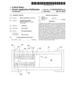
  • 1. (19) United States Van Beneden US 20120182116A1 (12) Patent Application Publication (10) Pub. No.: US 2012/0182116 A1 (43) Pub. Date: Jul. 19, 2012 (54) (75) (73) (21) (22) (86) (30) Jul. 15, 2009 THERMAL SWITCH Inventor: Assignee: Appl. No.: PCT Filed: PCT No.: § 371 (0X1)’ (2), (4) Date: Bruno Van Beneden, Zellik (BE) VISHAY RESISTORS BELGIUM BVBA, Bruxelles (Evere) (BE) 13/383,919 Jul. 15, 2010 PCT/EP2010/004328 Mar. 30, 2012 Foreign Application Priority Data (GB) ................................. .. 09123043 Publication Classi?cation (51) Int. Cl. H01H 71/20 (2006.01) (52) us. c1. ...................................................... .. 337/147 (57) ABSTRACT A thermal switch comprises a ?rst and second electrically conducting terminals and a pre-stressable electrically con ducting connecting device such as a compression spring member. The connecting device, in a compressed state, con tacts at most one of the ?rst and second terminals, and, in a released state, electrically connects the ?rst and second ter minals. The thermal sWitch further comprises a retainer device retaining the connecting device in the compressed state. The retainer device comprises a retaining material that melts at or above a predetermined temperature for releasing the connecting device into the released state. In the com pressed state of the connecting device, the ?rst and second terminals are electrically insulated from each other by a hol loW space formed between the connecting device and at least one of the ?rst and second terminals. 36
  • 2. Patent Application Publication Jul. 19, 2012 Sheet 1 0f 2 US 2012/0182116 A1 1 18 §-/ 0 N FIG.1 Kk (I) (l 1 06m’ / @ooibooc -. LKi O (‘0
  • 3. Patent Application Publication Jul. 19, 2012 Sheet 2 0f 2 US 2012/0182116 A1
  • 4. US 2012/0182116 A1 THERMAL SWITCH [0001] This present disclosure relates to thermal switches. [0002] A thermal sWitch may be used for protection of an electrical installation connected to a poWer supply against an electrical ?re caused by overheating of de?cient electrical contacts such as sWitch contacts or Wiring terminations. In particular, the thermal sWitch may be provided inproximity to an electrical plug, socket, sWitch or screW terminal etc. to detect an undue increase in temperature caused by a de?cient contact. Upon detection of an undue increase in temperature the thermal sWitch causes an interruption ofthe poWer supply. [0003] The thermal sWitch may be a device comprising ?rst and second electrically conducting terminals con?gured such that the device is non-conducting in a ?rst state, and conduct ing in a second state in response to a detection of a predeter mined temperature. The predetermined temperature is, on the one hand, Well above temperatures occurring during normal operation and, on the other hand, Well beloW temperatures that may cause an electrical ?re. The ?rst and second termi nals of the thermal sWitch may be connected to earth and neutral conductors or earth and live conductors to generate a fault, When the device is in the conducting state, that trips a residual current detector to interrupt the poWer supply. [0004] WO 2006/125996 Al discloses thermal sWitches capable of detecting When a build-up of heat occurs. In an embodiment, the terminals are separated by an electrically insulating spacer made of a material that melts at the prede termined temperature such that, When the spacer melts, the ?rst and second terminals contact each other under a biasing force, thereby activating the thermal sWitch. Such a meltable material isiin principleiWell suited for a thermal sWitch due to its precisely de?nable and knoWn melting point. A thermal sWitch including such an electrically insulating spacer, hoWever, requires a great biasing force for ensuring that the ?rst and second terminals contact each other reliably When the spacer melts. Such great biasing force can alter the state ofthe insulating spacer prior to its melting temperature, therefore reducing the reliability ofthe insulating spacer over time. [0005] One object of this disclosure is to provide a novel and improved thermal sWitchhaving a Well-de?ned activation temperature. [0006] Accordingly, the present disclosure provides a ther mal sWitch comprising ?rst and second electrically conduct ing terminals and a pre-stressable electrically conducting connecting device such as a compression spring member. The connecting device, in a compressed state, contacts at most one of the ?rst and second terminals, and, in a released state, electrically connects the ?rst and second terminals. The ther mal sWitch further comprises a retainer device retaining the connecting device in the compressed state. The retainer device comprises a retaining material that melts at or above a predetermined temperature for releasing the connecting device into the released state. In particular, the connecting device is irreversibly released into the released state. In the compressed state of the connecting device, the ?rst and sec ond terminals are electrically insulated from each other by a holloW space formed betWeen the connecting device and at least one of the ?rst and second terminals. [0007] The thermal sWitch of the present disclosure com prises the pre-stressable connecting device Which is retained in the compressed state by the retaining material at tempera Jul. 19, 2012 tures beloW the predetermined temperature. At higher tem peratures the retaining material melts and releases the con necting device into the released state. In the released state, the connecting device is reliably electrically connectedto the ?rst and second terminals. [0008] In contrast to prior art thermal sWitches, in the non conducting state of the thermal sWitch, the electrical insula tion betWeen the ?rst and second terminals is provided by the holloW space instead of by a meltable material. The holloW space, eg an air gap, replaces the meltable material in this respect. In particular, there is no electrically insulating mate rial melting at or above the predetermined temperature and acting as a spacer located betWeen the connecting device and the ?rst and second terminals in the non-conducting state of the thermal sWitch. Thus, a loWer biasing force is required for the connecting device. Further, there is no risk that residues of the retaining material remain betWeen the ?rst and second terminals impeding the conductibility ofthe thermal sWitch in the second state. [0009] In a feature, the retainer device comprises ?rst and second abutment members preferably formed separately from the terminals Wherein, in the compressed state of the connecting device, the connecting device is pre-stressed betWeen the ?rst and second abutment members. The ?rst and second abutment members are ?xedly attached to each other in the compressed state by means of the retaining material. Thus, the retainer device may beiignoring the retaining materialian at least tWo-piece device. [0010] In another feature, the ?rst and second abutment members comprise a sleeve member and a pin member, respectively. An electrically conducting collar is integrally formed With the sleeve member and an electrically conduct ing head is integrally formed With the pin member for the abutment of the connecting device. Alternatively, the collar and the head may be ?xedly attached to the sleeve member and pin member, respectively. Preferably, at least in the com pressed state of the connecting device, the pin member is at least partially received in the sleeve member. The sleeve member may therefore serve as a guidance for the pin mem ber. Preferably, in the compressed state of the connecting device, an annular gap is formed betWeen the sleeve member and the pin member. The annular gap is at least partially ?lled by the retaining material. Such an arrangement is easy to manufacture due to the fact that the retaining material mayi in a liquid phaseisimply be poured into the sleeve member. [0011] In still another feature, the ?rst and second abutment members comprise a ?rst attachment section and a second attachment section, respectively, for the attachment of the ?rst and second abutment members to each other. At least in the compressed state of the connecting device, the ?rst and second attachment sections are received in the connecting device. Preferably, the ?rst and second attachment sections correspond to the sleeve member and pin member as men tioned above, respectively. [0012] In another feature, the ?rst and second abutment members are moved apart by the connecting device upon the melting ofthe retaining material. [0013] In yet another feature, in the released state of the connecting device, the connecting device electrically con tacts the ?rst and second terminals via the ?rst and second abutment members. Thus, for ensuring electrical connection betWeen the ?rst and second terminals in the second state there is no need that the connecting device directly contacts
  • 5. US 2012/0182116 Al the ?rst and second terminals. Preferably, the non-direct con tact is established via the collar and head as mentioned above, respectively. [0014] The retaining material may comprise an electrically conducting material. Thus, even in the unlikely event that, in the conducting state ofthe thermal sWitch, the retaining mate rial gets in betWeen the connecting device and the retainer device, on the one hand, and the ?rst and second terminals, on the other hand, this Would not pose a problem since the electrical path betWeen the ?rst and second terminals Would not be obstructed. [0015] The thermal sWitch may comprise a resistor con nected in series With the connecting device, in particular a PTC thermistor and/or a fusible resistor. The additional resis tor may be used When the thermal sWitch is connected to earth and live conductors to avoid short-circuiting the live conduc tor to ground. Preferably, the resistor is con?gured such that it is moved by the connecting device upon pulling open the ?rst and second abutment members as mentioned above. [0016] In an additional feature, in the compressed state of the connecting device, the connecting device is held captive by the retainer device. [0017] Preferably, the connecting device and the retainer device form a multi-part subassembly of the thermal sWitch, in particular a three-part subassembly, Wherein, in the com pressed state of the connecting device, the subassembly is ?xedly attached to one ofthe ?rst and second terminals. The attachment to the ?rst or second terminal may be provided by the retaining material. Alternatively, the subassembly may be movable betWeen the ?rst and second terminals, in particular freely movable along an axis of the thermal sWitch. [0018] In a further feature, the thermal sWitch comprises a casing enclosing an internal space formed betWeen the ?rst and second terminals. The retainer device and the connecting device are received in the internal space. Preferably, the ?rst and second terminals comprise a ?rst end cap and a second end cap, respectively, closing an open ?rst front face and an open second front face opposite the ?rst front face of the casing, respectively. [0019] The present disclosure also pertains to an electrical installation comprising at least an earth terminal and a neutral terminal or an earth terminal and a live terminal, and further comprising a thermal sWitch as explained above, Wherein the ?rst terminal of said thermal sWitch is connected to the earth terminal and the second terminal of said thermal sWitch is connected to the neutral terminal or the live terminal. [0020] Further areas of applicability Will become apparent from the description provided herein. It should be understood that the description and speci?c examples are intended for purposes of illustration only and are not intended to limit the scope of the present disclosure. [0021] The draWings described herein are for illustration purposes only and are not intended to limit the scope of the present disclosure in any Way. [0022] FIG. 1 is a cross-sectional vieW of a thermal sWitch in accordance With the present disclosure, Wherein a connect ing device of the thermal sWitch is in a compressed state. [0023] FIG. 2 is a cross-sectional vieW of the thermal sWitch of FIG. 1, Wherein the connecting device is in a released state. [0024] The folloWing description is merely exemplary in nature and is not intended to limit the present disclosure, application, or uses. It should be understood that throughout Jul. 19, 2012 the draWings, corresponding reference numerals indicate like or corresponding parts and features. [0025] Referring noW to FIG. 1, an elongate, normally open thermal sWitch is illustrated. The thermal sWitch comprises an electrically insulating housing including a tubular casing 12 that encloses an internal space formed betWeen ?rst and sec ond metal end caps 14, 16 ofthe housing Which are provided for closing open ?rst and second front faces ofthe casing 12. The tubular casing 12 may be made from ceramic or plastic, for instance. The ?rst and second metal end caps 14, 16 act as ?rst and second terminals via Which the thermal sWitch may be connected to earth and neutral conductors or earth and live conductors (not shoWn). The thermal sWitch may be provided in proximity to an electrical contact of an electrical installa tion connected to a poWer supply to detect an undue increase in temperature Which may be caused by a de?cient contact. [0026] A subassembly 18 is receivedWithinthe housing 12, 14, 16. The subassembly 18 includes a connecting element designed as a helical spring 20 and a retainer device 24, 26, 36. The helical spring 20 may be made from stainless steel or the like. The retainer device 24, 26, 36 comprises electrically conducting ?rst and second metal abutment members 24, 26. The ?rst abutment member 24 comprises a sleeve (or ferrule) 28 and a circumferential collar 30 integrally formed With the sleeve 28 on that end ofthe sleeve 28 that faces the ?rst metal end cap 14 and extending radially outWardly from the sleeve 28. The second abutment member 26 comprises a pin 32 and a head 34 integrally formed With the pin 32 on that end ofthe pin 32 that faces the second metal end cap 16. The pin 32 is at least partly received Within the sleeve 28. The pin 32 and the sleeve 28 are in turn received Within the helical spring 20. [0027] FIG. 1 illustrates a compressed state of the helical spring 20 Which corresponds to a non-activated, non-con ducting state ofthe thermal sWitch. In the compressed state of the helical spring 20, the helical spring 20 is pre-stressed betWeen the collar 30 and the head 34. The sleeve 28 and the pin 32 Which act as ?rst and second attachment sections ofthe above-mentioned abutment members 24, 26 are ?xedly attached to each other by means of a solid, electrically con ducting retaining material 36 Which for manufacture of the thermal sWitch is poured into an annular gap formed betWeen the sleeve 28 and the pin 32. As a matter of course, the retaining material 36 is heated to a temperature above its melting point to enable the pouring. Thus, the helical spring 20 is held captive by the retainer device 24, 26, 36 in a pre-stressed state. The helical spring 20 and the retainer device 24, 26, 36 are undetachably coupled to each other in the non-activated state of the thermal sWitch. [0028] The retaining material 36 may be a metal compound or metal alloy, preferably lead(Pb)-free, having an eutectic melting temperature in the range of 50° C. to 200° C., for instance, such as an indium-bismuth-alloy having a melting temperature of eg 72° C. [0029] In addition, the subassembly 18 is ?xedly attached to the ?rst metal end cap 14 by the retaining material 36 to prevent movement of the subassembly 18 Within the above mentioned internal space of the tubular casing 12. The sub assembly 18, hoWever, does not contact the second metal end cap 16. Rather, the subassembly 18 is electrically insulated from the second metal end cap 16 by a holloW space 38 that is formed betWeen the subassembly 18 and the second metal end cap 16. Alternatively, the subassembly 18 may be mov able Within the tubular casing 12 or ?xedly attached to the tubular casing 12 such that the holloW space 38 is formed on
  • 6. US 2012/0182116 A1 both sides of the subassembly 18. Preferably, the hollow space 38 is ?lled With air. Preferably, the hollow space 38 has a breakdown voltage of 2 kV or greater, in particular 3 kV or greater. [0030] The retaining material 36 melts at or above a prede termined temperature. Upon melting ofthe retaining material 36 the retaining property of the retaining material 36 disap pears alloWing the helical spring 20 to break open the subas sembly 18 and to irreversibly decompress into a released state illustrated in FIG. 2 Which corresponds to an activated, con ducting state ofthe thermal sWitch. In the released state ofthe helical spring 20, the abutment members 24, 26 are detached from each other and pushed aWay from each other by the helical spring 20 such that the collar 30 of the sleeve 28 and the head 34 of the pin 32 are pressed against the ?rst and second metal end caps 14, 16. The holloW space 38 has disappeared. [0031] The internal space including the former holloW space 38 enclosed by the casing 12 and formed betWeen the ?rst and second metal end caps 14, 16 is noW entirely occu pied by the extended subassembly 18. In FIG. 2, ?rst and second parts of the retaining material 36 Which again solidi ?es after an interruption ofthe poWer supply to the electrical installation are stuck to the ?rst abutment member 24 and second abutment member 26, respectively. HoWever, any other arrangement or spreading ofthe retaining material 36 is possible in the activated state of the thermal sWitch. [0032] Preferably, in the released state ofthe helical spring 20, the helical spring 20 is still pre-stressed to ensure a loW contact resistance betWeen each ofthe ?rst metal end cap 14 and the collar 30, the collar 30 and the helical spring 20, the helical spring 20 and the head 34, and the head 34 and the second metal end cap 16. [0033] Thus, in the released state of the helical spring 20, the helical spring 20 is electrically connected to the ?rst and second metal end caps 14, 16 via the collar 30 and head 34. As a consequence, the ?rst and second metal end caps 14, 16 are electrically connected to each other, i.e. the thermal sWitch 20 is in an electrically conductive state Which state may be uti liZed to trip a residual current detector to interrupt the poWer supply. [0034] Additionally, the subassembly 18 may comprise a resistor 22 that is connected in series With the helical spring 20. The resistor 22 may be a thermistor, in particular a ceramic PTC (positive temperature coe?icient) thermistor, Which can limit the electrical current How in a certain time frame. The resistor 22 may also be a normal linear resistor or a fusible resistor able to interrupt electrical current levels of certain amplitude. Preferably, the resistor 22 is used if the thermal sWitch is connected betWeen earth and live conduc tors to limit the fault current to a pre-de?ned value. The resistor 22 may be omitted ifthe thermal sWitch is connected betWeen earth and neutral conductors. [0035] In principle, it Would be also feasible to design a thermal sWitch Which is similar to the thermal sWitch described above in that a helical spring is used Wherein, hoWever, the retainer device as described above is omitted and the holloW space is ?lledWith an electrically insulating spacer made of a material that melts at the predetermined tempera ture. Such a design, hoWever, is disadvantageous. This is due to the fact that such a sWitch is susceptible to malfunction if residues ofthe electrically insulating spacer remain betWeen the helical spring and at least one of the ?rst and second terminals although the spacer has melted. This is also due to Jul. 19, 2012 the fact that such an electrically insulating spacer can be altered or reduced in thickness, prior to its predetermined melting temperature, thereby reducing the long-term reliabil ity ofthe component. [0036] Those skilled in the art can noW appreciate from the foregoing description that the broad teachings ofthe present disclosure can be implemented in a variety of forms. There fore, While this disclosure has been described in connection With particular examples thereof, the true scope ofthe disclo sure should not be so limited since other modi?cations Will become apparent to the skilledpractitionerupon a study ofthe draWings, the speci?cation and the folloWing claims. 1 . A thermal sWitch comprising ?rst and second electrically conducting terminals and a pre-stressable electrically con ducting connecting device such as a compression spring member; said connecting device, in a compressed state, con tacting at most one of said ?rst and second terminals, and, in a released state, electrically connecting said ?rst and second terminals; and further comprising a retainer device retaining said connecting device in said compressed state; said retainer device comprising a retaining material that melts at or above a predetermined temperature for irreversibly releasing said connecting device into said released state; Wherein, in said compressed state of said connecting device, said ?rst and second terminals are electrically insulated from each other by a holloW space formed betWeen said connecting device and at least one of said ?rst and second terminals. 2. The thermal sWitch according to claim 1, Wherein said retainer device comprises ?rst and second abutment mem bers; andWherein, in said compressed state ofsaidconnecting device, said connecting device is pre-stressed betWeen said ?rst and second abutment members; said ?rst and second abutment members being ?xedly attached to each other in said compressed state by means of said retaining material. 3. The thermal sWitch according to claim 2 Wherein said ?rst and second abutment members comprise a sleeve mem ber and a pin member, respectively; an electrically conduct ing collar being integrally formed With said sleeve member and an electrically conducting head being integrally formed With said pin member for said abutment of said connecting device. 4. The thermal sWitch according to claim 3 Wherein, at least in said compressed state of said connecting device, said pin member is at least partially received in said sleeve member. 5. The thermal sWitch according to claim 4 Wherein, in said compressed state of said connecting device, an annular gap is formed betWeen said sleeve member and said pin member; saidannular gap being at least partially ?lledby saidretaining material. 6. The thermal sWitch according to claim 2 Wherein said ?rst and second abutment members comprise a ?rst attach ment section and a second attachment section, respectively, for said attachment of said ?rst and second abutment mem bers to each other; and Wherein, at least in said compressed state of said connecting device, said ?rst and second attach ment sections are received in said connecting device. 7. The thermal sWitch according to claim 2 Wherein said ?rst and second abutment members are moved apart by said connecting device upon said melting of said retaining mate rial. 8. The thermal sWitch according to claim 2 Wherein, in said released state of said connecting device, said connecting device electrically contacts said ?rst and second terminals via said ?rst and second abutment members.
  • 7. US 2012/0182116 A1 9. The thermal switch according to claim 1 Wherein said retaining material comprises an electrically conducting mate rial. 10. The thermal sWitch according to claim 1 Wherein said thermal sWitch comprises a resistor connected in series With said connecting device. 11. The thermal sWitch according to claim 1 Wherein, in said compressed state of said connecting device, said con necting device is held captive by said retainer device. 12. The thermal sWitch according to claim 1 Wherein said connecting device and said retainer device form a multi-part subassembly of said thermal sWitch; and Wherein, in said compressed state ofsaidconnecting device, said subassembly is ?xedly attached to one of said ?rst and second terminals or movable betWeen said ?rst and second terminals. 13. The thermal sWitch according to claim 1 Wherein said thermal sWitch comprises an electrically insulating casing enclosing an internal space formed betWeen said ?rst and Jul. 19, 2012 second terminals; said retainer device and said connecting device being received in said internal space. 14. The thermal sWitch according to claim 13 Wherein said ?rst and second terminals comprise a ?rst end cap and a second end cap, respectively, closing an open ?rst front face and an open second front face opposite said ?rst front face of said casing, respectively. 15. (canceled) 16. The thermal sWitch according to claim 4, Wherein said pin member and said sleeve member are received Within said connecting device. 17. The thermal sWitch according to claim 2 Wherein said ?rst and second abutment members are formed separately from the terminals. 18. The thermal sWitch according to claim 10 Wherein said resistor comprises at least one ofa PTC thermistor and fusible resistor.