3. Project Summary:
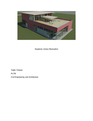
The proposed site that were given to renovate is located in Noblesville, Indiana. The site
itself sits on a 6.67 Acre lot and the existing building used to be run downed warehouse.
The task at hand was to renovate the ware-
house to fit the needs of using it as a public
library. We were also addressed with sev-
eral constraints that define the clear need
for X amount of rooms. The building con-
tains two meetings room, public restrooms
(First and Second floor), a welcoming entry
desk, a small children's help desk, open
area for stacks, staff work room / kitchen,
and a history room for viewing. The exterior of the building is composed of glass curtain
walls and red walls. This interior is laid out so that it best
fits the needs for the workers and the guest as well. The
entrance is a new modern vestibule that is simple and
helps the efficiency of the building .The rooms are pri-
marily laid out on the sides of the building to allow for
much room needed for stacks. The stairs is located in
the right corner of the building. The second floor is de-
sign for stacks and computer usage. There is a small
vestibule that extends out into the deck. The Green Roof is composed of a hardwood
walkway and grass. This from the exterior creates a very inviting and welcoming atmos-
phere. The building was finally designed to ensure that the guest using the library could
find everything with access .Ultimately through extensive work, I believe that this build-
ing meets all constraints and guidelines and best fits the task.
Code and Regulation:
Before designing the project we went a dived into the world of building regulations and
local ordinances. We first started to find the occupant load
and based on the International Building Code, the library
was considered to be a part of Assembly Group A-3. This
will ultimately effect part of the building itself. Based on
IBC Section 1004, I determined that the total occupant
load could only be 356 people. Then from this based on
IBC Section 2021, the minimum amount of exits needed
was 6. Based on the zoning map for Noblesville, Indiana.
The lot we are building on is for Planned Business. Addi-
tionally, Section 159.107 Noblesville Code of Ordinances, the purpose of this zoning
4. designation is to help well-planned businesses to adjust to a good spot. The lot is de-
signed to have parking lots and adequate services. The Keystone Library also fit the
minimum lot size which is 20,000 SF. (Section 159.107 Noblesville Code of Ordinances)
Floor Plan Analysis:
When designing the floor plan, I laid everything that best fit the needs of the people. The
Vestibule is located at the southeast
part of the building. This vestibule adds
a modern touch to the building. When
walking in the building the guest is ap-
proached with an entry desk. This is
where you can return and check out
books. Along the south wall contains
the history that was required and one
meeting room. I decided to place these
history room was placed near the en-
trance in order for any guest wanting to
visit the room with ease. The meeting
room also along the south wall is 474
SF. The north wall holds the head office, public restrooms, meeting room, elevator
shaft, and the mechanical room. The staff restroom/kitchen is located along the east
wall. The reason that all rooms are placed on the side is too allow room for much need
space. The biggest area in the building in the open area which is 5097 SF.
The second floor has more room for
stacks and computer terminals. There
are two ways to enter the second floor.
There is an elevator and stairwell lo-
cated at the north of the building. The
both lead to the second floor. The sec-
ond floor provides seating for anyone
that wishes to read books or do any-
thing. The computer terminals are at
the southern part of the second floor.
Adjacent to those are the public re-
strooms. Going to the outside deck,
there is wooden deck way that leads
around the building and to all exits.
There is also seating for anyone that wishes to sit outside. Ultimately I believe that this
building was laid out to fit the best interest of the guest and the possible client.
5. Calculations:
Determining the composite floor-load came with many considerations. The materials
used in a residential floor system significantly vary in a commercial building due to type
of the building. Commercial buildings are designed to carry larger loads and undergoes
great amounts of compression, while residential loads are designed for a small occu-
pant, thus creating a need for different building materials that can hold different loads.
The advantages of using a precast is it’s already pre cast and needs to be lifted. Sec-
ondly the second material required in a pre-cast is rebar. This creates an ease in the to-
tal amount of materials needed to lay a floor. When comparing two different concrete
floors there are different factors that are needed to take into consideration. One being
the price of each slab and the length it covers, ultimately you’ll want the most cost effec-
tive slab. Secondly you would want the slab that
can carry the designated load required in that situ-
ation. Typically both do a great job at what they do
though determining the load needed would come
down to mathematics. After that I started to calcu-
late the type of deck used on the roof. I first calcu-
lated the snow load, and based on the charts that
were given, the total came out to 22 psf. From
there I estimated the roof load, and this was deter-
mined by the type of roofing used. The dead load
totaled out to 24.65 psf. Finally I found the total de-
sign load (D + Lr + S), which came out to 66.65 psf.
I then accessed table to find the correct metal
decking to fit the needs. I found that a Simple Span
22F would best fit the design load. After taking
6. these calculations, we moved on to decide the beams we needed. The span of both the
interior and exterior joist came out to 24 ft. After deter-
mining the tributary width, we got the design load
which was 333.2 lb. /ft. The exterior design load was
166.25 lb. /ft. I then headed to the “Standard ASD
Load Table” and determined the joint designation. The
interior joist was determined to be a 16K4, which its
max load came to be 349 lbs. and the weight being
7.0lb. /ft. The exterior joist was a 14K1 and the max
load was 196 lb./ft. with a weight of 5.7 lb./ft.. After
that I began to assess the proper beam and girder
calculations. I used to basic beam formulas in order to
calculate and find the correct the interior beam I
chose was a W12x16. The girder I used was chosen
to be a W18x35. Both these were found using a data
table and based on the information calculated. The
next part was seeing if the water pressure that was
being pumped would reach minimum requirements.
The entire length of the pipe (Cast Iron), was 3.6
miles. The flow of the water ran at 100 gpm. I first calculated the static head by subtract-
ing the elevation of the water tower, 872.81 ft., by 782 ft. (Base elev. for Library). I then
began to find the total amount of head loss. I first found the equivalent length of all the
additionally plumbing fixtures in the pipe. I then used the Hazen-Williams formula to fig-
ure the total amount of head loss which came out to 8.04. I then found the dynamic
head, and converted the numbers over and found the dynamic pressure was 36.267 psi.
Based off of this I found that there is not enough water pressure to meet minimum re-
quirements. Additionally this meant that I needed to have a pressure valve to increase
the amount of pressure going into the building. The next set of calculations that ran
were finding the slope needed to wastewater discharge. I first found my crown eleva-
tion, horizontal distance, and then my inert elevation. Finally I found that the slope I
needed was being used was 2.97 which meets minimum requirements. The last set of
calculations I did was determine the storm water runoff and if there was a chance of a
retention pond. I calculated change in runoff the previous site. I found these by evaluat-
ing all the new surfaces. From there I found that there would not be a drastic change in
runoff therefore I would not need to implement a pond.
The use of glass in the building allows for sunlight to light up the interiors. This will ulti-
mately reduce the amount of electricity use during hours of operation. Additionally I've
added a vestibule on both the second and first floor in order to allow for less heat loss.
This also helps the building maintain the internal temperature. .This project provided
many obstacles that proved to be challenging. However the biggest hurdle I had to over-
come is all the math that was involved in finding the needed info. If I was given more
time, I would like to improve my plumbing systems and HVAC systems.