

Recommended
More Related Content
Viewers also liked
Similar to Unidrive m400 sheet issue 1
Similar to Unidrive m400 sheet issue 1 (18)
More from Toàn Huỳnh
More from Toàn Huỳnh (20)
Recently uploaded
Recently uploaded (20)
Unidrive m400 sheet issue 1
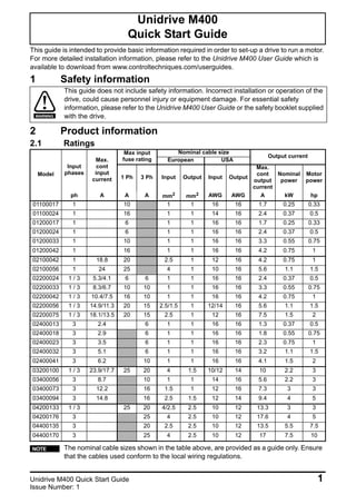
- 1. Unidrive M400 Quick Start Guide 1 Issue Number: 1 This guide is intended to provide basic information required in order to set-up a drive to run a motor. For more detailed installation information, please refer to the Unidrive M400 User Guide which is available to download from www.controltechniques.com/userguides. 1 Safety information 2 Product information 2.1 Ratings Unidrive M400 Quick Start Guide This guide does not include safety information. Incorrect installation or operation of the drive, could cause personnel injury or equipment damage. For essential safety information, please refer to the Unidrive M400 User Guide or the safety booklet supplied with the drive. Model Input phases Max. cont input current Max input fuse rating Nominal cable size Output current European USA 1 Ph 3 Ph Input Output Input Output Max. cont output current Nominal power Motor power ph A A A mm2 mm2 AWG AWG A kW hp 01100017 1 10 1 1 16 16 1.7 0.25 0.33 01100024 1 16 1 1 14 16 2.4 0.37 0.5 01200017 1 6 1 1 16 16 1.7 0.25 0.33 01200024 1 6 1 1 16 16 2.4 0.37 0.5 01200033 1 10 1 1 16 16 3.3 0.55 0.75 01200042 1 16 1 1 16 16 4.2 0.75 1 02100042 1 18.8 20 2.5 1 12 16 4.2 0.75 1 02100056 1 24 25 4 1 10 16 5.6 1.1 1.5 02200024 1 / 3 5.3/4.1 6 6 1 1 16 16 2.4 0.37 0.5 02200033 1 / 3 8.3/6.7 10 10 1 1 16 16 3.3 0.55 0.75 02200042 1 / 3 10.4/7.5 16 10 1 1 16 16 4.2 0.75 1 02200056 1 / 3 14.9/11.3 20 15 2.5/1.5 1 12/14 16 5.6 1.1 1.5 02200075 1 / 3 18.1/13.5 20 15 2.5 1 12 16 7.5 1.5 2 02400013 3 2.4 6 1 1 16 16 1.3 0.37 0.5 02400018 3 2.9 6 1 1 16 16 1.8 0.55 0.75 02400023 3 3.5 6 1 1 16 16 2.3 0.75 1 02400032 3 5.1 6 1 1 16 16 3.2 1.1 1.5 02400041 3 6.2 10 1 1 16 16 4.1 1.5 2 03200100 1 / 3 23.9/17.7 25 20 4 1.5 10/12 14 10 2.2 3 03400056 3 8.7 10 1 1 14 16 5.6 2.2 3 03400073 3 12.2 16 1.5 1 12 16 7.3 3 3 03400094 3 14.8 16 2.5 1.5 12 14 9.4 4 5 04200133 1 / 3 25 20 4/2.5 2.5 10 12 13.3 3 3 04200176 3 25 4 2.5 10 12 17.6 4 5 04400135 3 20 2.5 2.5 10 12 13.5 5.5 7.5 04400170 3 25 4 2.5 10 12 17 7.5 10 The nominal cable sizes shown in the table above, are provided as a guide only. Ensure that the cables used conform to the local wiring regulations. WARNING NOTE
- 2. 2 Unidrive M400 Quick Start Guide Issue Number: 1 Figure 2-1 Model number structure 3 Mechanical installation The drives can be panel mounted with 0 mm space between the drives. For further information on mechanical installation refer to the Unidrive M400 User Guide. To remove the terminal cover, use a flat bladed screwdriver to rotate the terminal cover locating clip by approximately 30° in a counter clockwise direction, and then slide the cover down. Table 3-1 Recommended torque settings Drive Size H W D M1 M2 ∅ A B mm in mm in mm in mm in mm in mm in mm in mm in 1 160 6.30 75 2.95 130 5.12 143 5.70 53 2.08 5 0.2 0.00 0.00 100 3.93 2 205 8.07 78 3.07 150 5.91 194 7.63 55 2.17 5 0.2 3 226 8.90 90 3.54 160 6.30 215 8.46 70.7 2.80 5 0.2 4 277 10.91 115 4.53 175 6.89 265 10.43 86 3.40 6 0.23 Model size Terminal block description Torque settings All Control terminals 0.2 N m (0.15 Ib ft) Relay terminals 0.5 N m (0.37 Ib ft) 1 Power terminals 0.5 N m (0.37 Ib ft) 2, 3, 4 1.4 N m (1.03 Ib ft) Derivative Electrical Specifications M400 - 03 4 00073 Product line: Frame size: Voltage rating: Current Rating : Heavy Duty current rating x10 Drive Format: A – AC in AC out A 1 - 100 V (100 - 120 10 %) - 400 V (380 - 480 10 %) 5 - 575 V (500 - 575 10 %) 6 - 690 V (500 - 690 10 %) 2 - 200 V (200 - 240 10 %) 4 ± ± ± ± ± A W M2 M2 B D B A H M1Cover release
- 3. Unidrive M400 Quick Start Guide 3 Issue Number: 1 4 Electrical installation Figure 4-1 below shows an overlay of the electrical connections / terminals available on the drive. For further information regarding terminal specification, cable sizes etc., refer to the Unidrive M400 User Guide. Figure 4-1 M400 Overlay of electrical connections 5 Keypad and display The keypad and display provide information to the user regarding the operating status of the drive and trip codes, and provide the means for changing parameters, stopping and starting the drive, and the ability to perform a drive reset. Figure 5-1 Unidrive M400 keypad detail T (1) The Enter button is used to enter parameter view or edit mode, or to accept a parameter edit. (2) The Navigation keys can be used to select individual parameters or to edit parameter values. In keypad mode, the ‘Up’ and ‘Down’ keys are also used to increase or decrease the motor speed. (3) The Start key is used to start the drive in keypad mode. (4) The Stop / Reset key is used to stop and reset the drive in keypad mode. It can also be used to reset the drive in terminal mode. (5) The Escape key is used to exit from the parameter edit / view mode or disregard a parameter edit. 9 10 11 12 Zero frequency Run forward 24 V user Digital I/O1 Digital I/O 2 Digital input 3 13Run reverse Digital input 4 14 Digital input 5 Digital I/O L1 L2 L3 1 ph/3 ph AC power supply 1 2 3 Braking resistor (optional) 0 V Analog I/O Analog input 1+ Analog input 1- U BR + _ V W Thermal relay 41 42 Drive ok Relay AC supply DC bus/Brake Motor 6 0 V 15 Digital input 6 16 Digital input 7 7 8 Analog output 1 Analog output 2 Jog forward Analog input 1/ Analog input 2 select 17 24 V user 33 User enable 2 / STO input 2 0 V STO2 34 STO2 31 STO1 32 0 V STO1 User enable 1 / STO input 1 Safe Torque Off 4 10 V user 5 Analog input 2 Frequency reference 1 Frequency reference 2 Frequency output Torque producing current output 1 2 3 4 5
- 4. 4 Unidrive M400 Quick Start Guide Issue Number: 1 6 Running the motor This section takes a new user through all the essential steps to running a motor for the first time. Section 4 provides the minimum connections required to connect and run a motor. The most commonly used parameters are shown on the terminal cover of the drive. 0478-0040-01 Action Detail Before power up Ensure: • The drive enable signal is not given, terminal 31 and 34 is open • The run signal is not given, terminal 12/13 is open • The motor is connected to the drive • The motor connection is correct for the drive Δ or Y • The correct supply voltage is connected to the drive Power up the drive Ensure: • The drive displays: Inhibit Enter minimum and maximum speeds Enter: • Minimum speed Pr 00.001 (Hz) • Maximum speed Pr 00.002 (Hz) Enter accel and decel rates Enter: • Acceleration rate Pr 00.003 (s/100 Hz) • Deceleration rate Pr 00.004 (s/100 Hz) Enter motor nameplate details Enter: • Motor rated current in Pr 00.006 (A) • Motor rated speed in Pr 00.007 (rpm) • Motor rated voltage in Pr 00.008 (V) • Motor rated power factor in Pr 00.009 • If the motor is not a standard 50/60 Hz motor, set Pr 00.039 accordingly Ready to autotune Autotune The drive is able to perform either a stationary or a rotating autotune. The motor must be at a standstill before an autotune is enabled. To perform an autotune: • Set Pr 00.038 = 1 for a stationary autotune or set Pr 00.038 = 2 for a rotating autotune • Close the drive enable signal (terminal 31 & 34). The drive will display ’Ready’. • Close the run signal (terminal 12 or 13). The lower display will flash ’tuning’ while the drive is performing the autotune. • Wait for the drive to display ‘Inhibit’ and for the motor to come to a standstill. • Remove the drive enable and run signal from the drive. Autotune complete When the autotune has been completed, Pr 00.038 will be set to 0 Save parameters Save parameters Select ‘SAVE’ in Pr mm.000 (alternatively enter a value of 1000) and press the Stop / Reset button to save parameters. Ready to run Run The drive is now ready to run the motor. Increasing and decreasing speed Turning the speed potentiometer will increase and decrease the speed of the motor. Stopping To stop the motor under ramp control, open either the run forward or run reverse terminal. If the enable terminal is opened while the motor is running, the motor will coast to a stop. Pr 02 tPr 01 100Hz Pr 03 t Pr 04 Mot X XXXXXXXXX No XXXXXXXXXX kg IP55 I.cl F C 40 s S1° V Hz min -1 kW cosφ A 230 400 50 1445 2.20 0.80 8.50 4.90 CN = 14.5Nm 240 415 50 1445 2.20 0.76 8.50 4.90 CN = 14.4Nm CTP- VEN 1PHASE 1=0,46A P=110W R.F 32MN I.E.C341(87) cos ∅ σLS RS