Here are the key points about axles:1.1.1 Front Axle- Connects the front wheels to the vehicle and allows them to rotate freely. - Supports part of the vehicle weight and transmits steering forces.- Usually independent suspension with coil or leaf springs. Allows wheels to move up/down independently.- May have solid beam or I-beam design.1.1.2 Rear Axle- Connects the rear wheels to the vehicle and allows them to rotate freely.- Supports around 60% of the total vehicle weight. Heavier duty than front axle. - Can have solid beam, banjo, or live axle design. Live
•
0 likes•717 views


Recommended
More Related Content
What's hot
What's hot (20)
Similar to Here are the key points about axles:1.1.1 Front Axle- Connects the front wheels to the vehicle and allows them to rotate freely. - Supports part of the vehicle weight and transmits steering forces.- Usually independent suspension with coil or leaf springs. Allows wheels to move up/down independently.- May have solid beam or I-beam design.1.1.2 Rear Axle- Connects the rear wheels to the vehicle and allows them to rotate freely.- Supports around 60% of the total vehicle weight. Heavier duty than front axle. - Can have solid beam, banjo, or live axle design. Live
Similar to Here are the key points about axles:1.1.1 Front Axle- Connects the front wheels to the vehicle and allows them to rotate freely. - Supports part of the vehicle weight and transmits steering forces.- Usually independent suspension with coil or leaf springs. Allows wheels to move up/down independently.- May have solid beam or I-beam design.1.1.2 Rear Axle- Connects the rear wheels to the vehicle and allows them to rotate freely.- Supports around 60% of the total vehicle weight. Heavier duty than front axle. - Can have solid beam, banjo, or live axle design. Live (20)
Here are the key points about axles:1.1.1 Front Axle- Connects the front wheels to the vehicle and allows them to rotate freely. - Supports part of the vehicle weight and transmits steering forces.- Usually independent suspension with coil or leaf springs. Allows wheels to move up/down independently.- May have solid beam or I-beam design.1.1.2 Rear Axle- Connects the rear wheels to the vehicle and allows them to rotate freely.- Supports around 60% of the total vehicle weight. Heavier duty than front axle. - Can have solid beam, banjo, or live axle design. Live
- 1. A PROJECT REPORT ON STRUCTURAL ANALYSIS OF REAR DEAD AXLE USING FEA Submitted in partial fulfillment of the award for the degree of BACHELOR OF TECHNOLOGY IN MECHANICAL ENGINEERING BY G.K.S.RAMA KRISHNA 12K65A0306 P.SANDEEP 11K61A0384 S.K.SUMANTH VARMA 11K61A0397 K.KUMAR RAJA 12K65A0309 Under the esteemed guidance of R. NARENDRA DEPARTMENT OF MECHANICAL ENGINEERING SASI INSTITUTE OF TECHNOLOGY & ENGINEERING (Accredited by NAAC with ‘A’ Grade, Approved by A.I.C.T.E New Delhi and Affiliated to JNTU, KAKINADA and SBTET, Hyderabad) TADEPALLIGUDEM 2014-2015
- 2. SASI INSTITUTE OF TECHNOLOGY & ENGINEERING (Accredited by NAAC with ‘A’ Grade, Approved by A.I.C.T.E New Delhi and Affiliated to JNTU, KAKINADA and SBTET, Hyderabad) TADEPALLIGUDEM Department of mechanical engineering CERTIFICATE This is to certify that this titled STRUCTURAL ANALYSIS OF REAR DEAD AXLE USING FEA, has been submitted by G.K.S.RAMA KRISHNA (12K65A0306), P.SANDEEP (11K61A0384), S.K.SUMANTH VARMA (11K61AO397), K.KUMAR RAJA (12K65A0309) to the Jawaharlal Nehru Technological University, Kakinada during the academic year 2014- 2015In the partial fulfillment for the award of Degree of BACHELOR OF TECHNOLOGY in MECHANICAL Engineering, is a record of bonafide work carried out by him. The results embodied in this report have not been submitted by the student to any other University or Institution for the award of any degree or diploma. Internal Project Guide Head of the Department Mr. R. NARENDRA Dr. R.B.CHOUDARY Assistant Professor Professor Dept of Mech Engg. Dept of Mech Engg. External Examiner
- 3. i ACKNOWLEDGEMENT We express our sincere thanks to The Management of “Sasi Institute of Technology and Engineering” for the facilities made available for completion of project. We convey our deep sense of gratitude to Dr. K.BHANU PRASAD, Principle under whose guidance and encouragement we have carried out this work successfully. We would like to express our sincere thanks to Prof. R.B.CHOUDARY, Head of the department of Mechanical Engineering. We express our heart full thanks to our esteemed guidance R.NARENDRA, for the grateful patience he has shown towards our work for this timely advices and guidance. We are also thankful to all Staff and Technicians of Mechanical Department for their support during the course of the work. We are also thankful to the Library (& Library Staff) of the college for the reference books which helped us gathering some information about the project. PROJECT ASSOCIATES G.K.S.RAMA KRISHNA P.SANDEEP S.K.SUMANTHVARMA K.KUMAR RAJA
- 4. ii ABSTRACT An axle is a central shaft for a rotating wheel. On wheeled vehicles, the axle may be fixed to the wheels, rotating with them, or fixed to its surroundings, with the wheels rotating around the axle, as well as to maintain the position of the wheels relative to each other and to the vehicle body. The axles in a system must also bear the weight of the vehicle plus any cargo, about 60 percent of the total vehicle weight is taken up by the rear axle. The component will be drafted in solid works. Applications resulting from the advancement in computer technology made numerical methods to be employed in analyzing various stresses acting on a component. One such technique is the “Finite Element Analysis”, which is meant to analyze the design of rear dead axle under working conditions by using ANSYS. Using Finite Element Method an effort is made to analyze the load distribution within the rear axle, structural analysis is done on the axle to find out the varying stresses, displacements and frequencies which occur by the forces developed due to rotation By considering present conditions the loads will be applied on the component by using work bench. Finally the stresses, displacement and frequencies are varied for different materials to suggest which is suitable for the vehicles.
- 5. iii TABLE OF CONTENTS PAGE.NO ACKNOWLEDGEMENT i ABSTRACT ii LIST OF FIGURES vii LIST OF TABLES ix CHAPTER 1: INTRODUCTION TO AXLE 1.1 Introduction 1 1.1.1 Front Axle 1 1.1.2 Rear Axle 3 1.2 Structural Features of Axle 4 1.2.1 Straight Axle 5 1.2.2 Split Axle 5 1.2.3 Tandem axle 5 1.3 Axle Specifications 6 1.3.1 Dimensions of Axle 6 1.3.2 Design Restriction 6 1.3.3 Loads 7 CHAPTER2: LITERATURE SURVEY 2.1 Definition 8 2.2 History 8 2.3 Introduction 9 2.4 Description 10 2.4.1 Weight Reduction 11 2.4.2 Features 11 2.4.3 Benefits 11 2.4.4 Cross Section of Axle 12 2.4.4.1 I-Section Beam 12 CHAPTER3: MATERIAL SELECTION
- 6. iv 3.1 Introduction 14 3.2 Engineering Requirements 15 3.2.1 Mechanical Properties 15 3.2.2 Thermal Properties 16 3.2.3 Electrical Properties 17 3.2.4 Magnetic Properties 18 3.2.5 Chemical Properties 18 3.3 Classification of Engineering Materials 18 3.3.1 Metals 19 3.4 Selection of Materials 23 3.4.1 Ductile Cast Iron 23 3.4.1.1 Chemical Composition 23 3.4.1.2 Mechanical Properties 24 3.4.1.3 Thermal Properties 24 3.4.2 High Grade Steel 24 3.4.2.1 Chemical Composition 24 3.4.2.2 Mechanical Properties 25 3.4.2.3 Thermal Properties 25 CHAPTER 4: SOLIDWORKS 4.1 Introduction 26 4.2 Starting of SolidWorks 27 4.2.1 Checking the Option Setting 27 4.2.2 General Toolbox 28 4.3 Generating New Part 29 4.4 Sketching 30 CHAPTER 5: FINITE ELEMENT METHOD 5.1 Introduction 33 5.2 Boundary Conditions of FEM 34 5.3 Description of FEM 35 5.3.1 Type of Elements 36 5.3.2 Number of Elements 36
- 7. v 5.3.3 Size of Elements 36 5.4 Finite Element Analysis 38 5.4.1 Type of Analysis 38 5.4.1.1 Structural Analysis 38 5.4.1.2 Vibration Analysis 38 5.5 Finite Element Process 38 5.6 Introduction to Ansys Software 39 5.6.1 Various Stages of Ansys 40 5.6.2 Pre processor 40 5.6.3 Meshing 40 5.6.3.1 Manual 40 5.6.3.2 Mesh Control 41 5.6.3.3 Smart Sizing of Elements 41 5.6.4 Solution 41 5.6.5 Post-Processor 41 5.7 Structural Analysis 42 5.7.1 Model Analysis 42 5.7.1.1 Definition 42 5.7.1.2 Uses of Model 42 5.7.2 Static Analysis 42 5.7.2.1 Definition 42 5.7.2.2 Loads in Static Analysis 43 5.8 Advantages of FEM 43 5.9 Disadvantages of FEM 44 CHAPTER 6: MODELLING & STRUCTURAL ANALYSIS OF TANDEM AXLE 6.1Problem Definition 45 6.2 Analytical Method 45 6.2.1Moment of Inertia of I-Section 45 6.3 Calculation of Load 46 6.4 Modelling of Tandem Axle in 3D-Solid 46
- 8. vi 6.4.1 Creating Model 46 6.5 Structural Analysis of Rear Dead Axle 50 6.5.1 Static Analysis 50 6.5.2 Results 54 6.5.2 Modal Analysis 60 6.5.5 Results 62 CHAPTER 7: CONCLUSION 72 CHAPTER 8: REFERENCES 73
- 9. vii LIST OF FIGURES FIG. NO PAGE. NO 2.4.4.1 Rear Dead Axel 14 4.2.1 SolidWorks Windows 29 4.2.1.1 System Option Dialogue Box 30 4.2.2 Tool Bar Menu 31 4.3 New Document Window 32 6.2.1 I-Cross Section of Axle 47 6.4.1 2-D Line Diagram 50 6.4.1.1 Mirror Image of Solid 51 6.4.1.2 Extruded Image of Solid 51 6.4.1.3 Isometric View of Solid 52 6.5.1.1 Importing Of Geomentry 53 6.5.1.2 Ductile Cast Iron 54 6.5.1.3 High Grade Steel 54 6.5.1.4 Meshing 56 6.5.1.5 Applying Loads and Support 56 6.5.2.1 Total Deformation X-Direction 57 6.5.2.2 Total Deformation Y-Direction 57 6.5.2.3 Total Deformation Z-Direction 58 6.5.2.4 Von-Mises X-Direction 58 6.5.2.5 Von-Mises Y-Direction 59 6.5.2.6 Von-Mises Z-Direction 59
- 10. viii 6.5.3.1 Total Deformation X-Direction 60 6.5.3.2 Total Deformation Y-Direction 60 6.5.3.3 Total Deformation Z-Direction 61 6.5.3.4 Von-Mises X-Direction 61 6.5.3.5 Von-Mises Y-Direction 62 6.5.3.6 Von-Mises Z-Direction 62 6.5.4.1 Importing Geomentry 63 6.5.4.2 Ductile Cast Iron 64 6.5.4.3 High Grade Steels 64 6.5.4.4 Fixed Supports 65 6.5.5.1 Total Deformation 1 65 6.5.5.2 Total Deformation 2 66 6.5.5.3 Total Deformation 3 66 6.5.5.4 Total Deformation 4 67 6.5.5.5 Total Deformation 5 67 6.5.5.6 Total Deformation 6 68 6.5.6.1 Total Deformation 1 68 6.5.6.2 Total Deformation 2 69 6.5.6.3 Total Deformation 3 69 6.5.6.4 Total Deformation 4 70 6.5.6.5 Total Deformation 5 70 6.5.6.6 Total Deformation 6 71 6.5.7.1 Ductile Cast Iron Graph 69 6.5.7.2 High Grade Steel Graph 70
- 11. ix LIST OF TABLES TABLE. NO PAGE. NO 1.3.1 Dimensions of Axle 7 1.3.2 Design Restriction 8 1.3.3 Load onAxle 8 3.1 Factor Effecting Selection of Materials 15 3.2.2 Thermal Conductivity of Materials 23 3.3.1 Important Grouping of Materials 23 3.3.2 Properties for Grouping of Materials 24 3.4.1.3 Mechanical Properties for DCI 26 3.4.1.4 Thermal Properties for DCI 26 3.4.2.3 Mechanical Properties for HGS 27 3.4.2.3 Thermal Properties for HGS 27 5.2 Various Applications of FEA 36 5.6.1 Various Stages of Ansys 42 6.5.1 Meshing Parameters 55 6.6.1 Static Analysis Results 73 6.6.2 Modal Analysis Results 73
- 12. x
- 13. Structural Analysis of Rear Dead Axle by Using FEA 1 1. INTRODUCTION OF AXLE 1.1 Introduction An axle is a central shaft for a rotating wheel or gear. On wheeled vehicles, the axle may be fixed to the wheels, rotating with them, or fixed to the vehicle, with the wheels rotating around the axle. In the former case, bearings or bushings are provided at the mounting points where the axle is supported. In the latter case, a bearing or bushing sits inside a central hole in the wheel to allow the wheel or gear to rotate around the axle. Sometimes, especially on bicycles, the latter type axle is referred to as a spindle. During the vehicle operation, road surface irregularity causes cyclic fluctuation of stresses on the axle, which is the main load carrying member. Therefore it is important to make sure whether the axle resists against the fatigue failure for a predicted service life. Axle experiences different loads in different direction, primarily vertical beaming or bending load due to curb weight and payload, torsion. Due to drive torque, cornering load and braking load. In real life scenario all these loads vary with time. Vertical beaming is one of the severe and frequent loads on an axle Due to their higher loading capacity; solid axles are typically used in the heavy commercial vehicles. During the vehicle service life, dynamic forces caused by the road surface roughness produce dynamic stresses and these forces lead to fatigue failure of axle housing, which is the main load carrying part of the assembly. Axles are classified into 2 types, they are 1. Front Axle 2. Rear Axle 1.1.1 Front Axle: Front axle wheels consist of wheel alignment and steering mechanism that gives the vehicle directional stability promotes ease of steering and reduces tire wear to a minimum. A wheel is said to have directional stability or control if it can: - run straight down a road, - enter and leave a turn easily, and
- 14. Structural Analysis of Rear Dead Axle by Using FEA 2 - resist road shocks. The front wheel alignment depends upon the following factors: a. Camber b. King pin inclination c. Caster a. Camber: Camber is the tilting in or out of the front wheels from the vertical when viewed from the front of the vehicle. If the top of the wheel tilts out, it has "positive" camber. If the top of the wheel tilts in, it has "negative" camber. The amount of tilt measured in degrees from the vertical, is called "camber angle". Any amount of camber, positive or negative, tends to cause uneven or more tyrewear on one side than on the other side. Camber should not exceed two degrees. b. King-pin inclination: The king-pin inclination (or steering axle inclination) is the angle between the verticalline and centre of the kingpin or steering axle, when viewed from the front of the vehicle. The king-pin inclination is absolutely necessary due to the following reasons: i. It helps the car to have steering stability. ii. It makes the operation of the steering quite easy particularly when the vehicle is stationary. iii. It helps in reducing the wear on the tyre. c. Included angle: The combined camber and king-pin inclination is called the "included angle". This angle is important because it determines the point of intersection of the wheel and king pin center lines. This in turn determines whether the wheel will tend to toe-out or toe-in. i. If the point of intersection is above the ground, the wheel tends to toe-in. ii. If it is below the ground, the wheel tends to toe-out.
- 15. Structural Analysis of Rear Dead Axle by Using FEA 3 iii. If it is at the ground, the wheel keeps its straight position without any tendency to toe-in or toe-out. In this position the steering is called center point steering. d. Caster: The angle between the king-pin center line (or steering axis) and the vertical, in the plane of the wheel is called Caster angle. If the King-pin center line meets the ground at a point ahead of the vertical center line, it is called positive caster while if it is behind the vertical, wheel center Front line it is called negative caster. The caster angle in modern vehicles ranges from 2° to 8°. 1.1.2 Rear Axle: Rear axle is used to support the whole weight of the vehicle and transmits power to the rear wheels. It bears the load up to 50% to 80% weight of the vehicle. Rear axle transmits the power and supports the vehicle. Based on the transmission system and the weight supporting of the vehicle rear axle is divided into two types. They are: a. Live axle b. Dead axle a. Live axle:The rear drive axles transfer power from the differential assembly to the rear wheels. There are two major kinds of drive axle designs. One is the solid drive axle and the other is the independently suspended drive axle A solid drive axle or live axle is a hardened-steel shaft. Each rear axle assembly in solid axle rear suspension systems has two. External splines on the inboard (inner) end of each axle mate with internal splines on the differential side gear to which it is connected. An axle flange at the outboard (outer) end of each axle acts as a wheel hub. It provides the mounting surface for the brake drum or rotor and the wheel. The brake assembly and wheel are installed directly on the flange wheel studs. Each shaft is supported on the outboard end by an axle bearing, also called a wheel bearing. The axle bearing can be installed on the shaft or in the axle tube.
- 16. Structural Analysis of Rear Dead Axle by Using FEA 4 Axle bearings that are installed on the shaft are usually packed with grease. An axle seal is pressed into the housing behind, or on the inboard side of, the bearing. The lip of the seal seats against a machined area of the shaft. This seal keeps rear end lubricant from reaching the bearing. An outer seal prevents water and dirt from leaking through the outer ends of the rear axle housing and entering the bearing. Axle bearings that are installed in the housing are lubricated by rear end lubricant (gear oil). When the vehicle makes a turn, lubricant is thrown outward from the carrier, reaching the axle bearing. An axle seal is installed in front of, or on the outboard side of, the bearing to keep lubricant from leaking out from the outer ends of the rear axle housing. The shaft is held in place by a clip as explained in the next section. An axle bearing installed on the shaft is held in place by an axle collar. The axle collar is tightly pressed on the shaft. In addition, some will have a spacer to keep the bearing at the proper distance from the end of the axle. The axle retainer plate holds the axle and axle bearing to the axle tube. b. Dead Axle (Lazy Axle):A dead axle, also called lazy axle, is not part of the drive train but is instead free-rotating. The rear axle of a front-wheel drive car is usually a dead axle. Many trucks and trailers use dead axles for strictly load-bearing purposes. A dead axle located immediately in front of a drive axle is called a pusher axle. A tag axle is a dead axle situated behind a drive axle. Dead axles are also found on semi-trailers, farm equipment, and certain heavy construction machinery serving the same function. On some vehicles (such as motor coaches), the tag axle may be steerable. In some designs the wheels on a lazy axle only come into contact with ground when the load is significant, thus saving unnecessary tire wear 1.2 Structural Features of Axles Based on the structural features axle is divided into 3 types, they are 1. Straight axle 2. Split-axle 3. Tandem axle
- 17. Structural Analysis of Rear Dead Axle by Using FEA 5 1.2.1 Straight Axle: A straight axle is a single rigid shaft connecting a wheel on the left side of the vehicle to a wheel on the right side. The axis of rotation fixed by the axle is common to both wheels. Such a design can keep the wheel positions steady under heavy stress, and can therefore support heavy loads. Straight axles are used on trains (that is locomotives and railway wagons), for the rear axles of commercial trucks, and on heavy duty off-road vehicles. The axle can optionally be protected and further reinforced by enclosing the length of the axle in housing 1.2.2 Split-Axle: In split-axle designs, the wheel on each side is attached to a separate shaft. Modern passenger cars have split drive axles. In some designs, this allows independent suspension of the left and right wheels, and therefore a smoother ride. Even when the suspension is not independent, split axles permit the use of a differential, allowing the left and right drive wheels to be driven at different speeds as the automobile turns, improving traction and extending tire life. 1.2.3 Tandem Axle: A tandem axle is a group of two or more axles situated close together. Truck designs will use such a configuration to provide a greater weight capacity than a single axle. Semi-trailers usually have a tandem axle at the rear. In heavy trucks tandem refers to two closely spaced axles. Legally defined by the distance between the axles (up to 2.5m or 40 to 96inches), mechanically there are many configurations. Either or both axles may be powered, and often interact with each other. In some vehicles both axles are typically powered and equalized, in the other vehicles one axle is typically unpowered, and can often be adjusted to load, and even raised off the ground, turning a tandem into a single axle.
- 18. Structural Analysis of Rear Dead Axle by Using FEA 6 1.3 Axle Specifications 1.3.1 Dimensions of Axle: Table1.3.1 Dimensions of axle Wheel Base 4330 mm Overall Length 7766 mm Overall Width 2425 mm Front Track 1915 mm Rear Track 1816 mm Min. Ground Clearance 253 mm Min. Turning Circle Diameter 17500 mm Loading Body Length 5640 mm Max. Speed In Top Gear 74.5 kmph Maximum Grade ability 12% 1.3.2 Design Restriction: Table1.3.2 Design Restriction Maximum track 2160.5 mm Spring mounting centre 810-910 mm Bearing shoulder to bearing shoulder 2040.5 mm Overall width 2590.99 mm Max tire static load radius 540.6 mm Beam drop “S” 90.4mm Beam drop “C” 30.81mm
- 19. Structural Analysis of Rear Dead Axle by Using FEA 7 1.3.3 Loads: Table1.3.3 Load on axle Unloaded Loaded Front Axle 2420 6000 Rear Axle 1820 10200 Total 4240 16200
- 20. Structural Analysis of Rear Dead Axle by Using FEA 8 2. LITERRATURE SURVEY 2.1 Definition A tandem axle is a group of two or more axles situated close together. Truck designs will use such a configuration to provide a greater weight capacity than a single axle. Semi-trailers usually have a tandem axle at the rear. 2.2 History The Hendrickson story began in 1913 with the founding of The Hendrickson Motor Truck Company by inventor and businessman Magnus Hendrickson. This small Chicago-based manufacturing company built trucks often equipped with cranes, which were used to haul stone and other building materials. In 1926, Hendrickson introduced the first tandem truck suspension, which mounted the axles on each end of an equalizing beam. This unique "walking beam" design distributed the truck's load evenly between the two rear axles, which improved traction and greatly reduced the effects of bumps and potholes in the road. The walking beam soon gained widespread acceptance among the industry's new 6x4 "six wheeler" trucks, which allowed more payload. In 1978, The Boler Company, whose holdings included manufacturers of leaf springs and metal bumpers, purchased Hendrickson. In the years that followed, Hendrickson would expand into or acquire additional businesses in related areas—trailer suspension systems, auxiliary axle systems, springs, metal bumpers, and other heavy-duty components. Eventually Hendrickson sold the truck manufacturing operation to focus solely on suspension systems and related components. Today, Hendrickson is comprised of state- of-the-art facilities, technical centers and manufacturing centers,in the United States, Canada, Mexico, the United Kingdom, France, Austria, Romania, Turkey, India, China and Australia.
- 21. Structural Analysis of Rear Dead Axle by Using FEA 9 At Hendrickson, we commit to serving the transportation industry with innovative products that help improve productivity and profitability. Across the globe, our dedicated employees champion Hendrickson’s proud heritage through creativity, integrity and superior service. Our legacy embodies 100 years as the leading innovator and manufacturer of suspension systems and components for the global heavy-duty vehicle industry. 2.3 Introduction The auto industry is one of the key sectors of the Indian economy. The Industry comprises of automobile and the auto components sectors and encompasses commercial vehicles, multi-utility vehicles, passenger cars, two wheelers, three wheelers and related auto components. During last few decades due to global economic scenario optimum vehicle design is major concern. To accomplish the need to design a moderate car, the structural engineer will need to use imaginative concepts. The demands on the automobile designer increased and changed rapidly, first to meet new safety requirements and later to reduce weight in order to satisfy fuel economy requirements. Experience could not be extended to new vehicle sizes, and performance data was not available on the new criteria. Mathematical modeling was therefore a logical avenue to explore. Most recently, the finite element method, a computer dependent numerical technique, has opened up a new approach to vehicle design. During the vehicle operation, road surface irregularity causes cyclic fluctuation of stresses on the axle, which is the main load carrying member. Therefore it is important to make sure whether the axle resists against the fatigue failure for a predicted service life. Axle experiences different loads in different direction, primarily vertical beaming or bending load due to curb weight and payload, torsion. There had been exhaustive efforts to develop thefront axle design by studying the noise and vibration analysis atstatic and dynamic loading conditions. The model selected is thatof a light commercial vehicle (LCV) which has a gross vehicle load of around 5-10 tons. The front basically is of drop forged steel type depending upon the extent of total load the LCVexperiences. The collapse of LCV axle (front) while dynamic and static loading conditions is of huge apprehension to both goods and human lives, hence it becomes essential to scrutinize the structural integrity of the axle to endure characteristic such loading which can build up stresses in the same being consequential to fracture and finally failure. Stressed regions dueto vehicle static load, braking torque, and during turning is established and the front axle beam is investigated to find out its factor of safety and maximum deformation under the mentioned conditions. The present work aims to determine the load capacity of the front rigid axle of a LCV and determine its behaviour at static and dynamic conditions.This paper analysis the static, transient and modal analysis of the front axle beam. The geometry of axle is created in Pro-E WildFire5.0 software which is imported to ANSYS14.5. A fine congregate finite element model (meshed) is generated using the software to assess thestrength and capability of the product to survive against all forces and vibrations.
- 22. Structural Analysis of Rear Dead Axle by Using FEA 10 The front dead axle supports the weight of front part of the vehicle, facilitates steering, absorbs shocks which are transmitted due to road surface irregularities and also absorbs torque applied on it due to braking of vehicle. Front axle is made of I-section in the middle portion and circular or elliptical section or I section at the ends. The special x- section of the axle makes it able to withstand bending loads due to weight of the vehicle and torque applied due to braking. A typical LCV front axle consists of main beam, stub axle, and swivel pin or kingpin. The wheels are mounted on stub axles. The front axle beam is subjected to bending loads due to vertical forces due to mass present above in static condition of the vehicle, while driving a truck around a corner results in multiple forces such as twisting forces on kingpin or steering knuckle, axial forces between Pad and spring interface along the length of the beam and unsymmetrical vertical loads due to centrifugal action. Worst situation arises while a cornering truck is braked to stop giving rise to turning moment on Pad and a retarding force acting on the surface of the Pad in the sense of vehicle motion. Current article carries on the numerical simulation towards the front axle to understand comprehensively the automobile front axle’s stress, the strain distribution and the vibration frequency under different varieties of conditions, and provides the scientific theoretical base for the designer, thus improves design quality, shortens design cycle and reduces design cost. Various experiments and numerical methods were adopted by Leon et al. to obtain the stress analysis of a frontal truck axle beam. The results obtained by finite element method were verified experimentally using photo stress. [1] Based on an experimental and numerical analysis of a tractor’s front axle carried out by Mahanty et al, redesign was carried out for the front axle for weight optimization and easy manufacturability. Five different models were proposed based on ease of manufacturing and weight reduction. The results obtained by finite element method were analyzed by thirteen different certification test load conditions. [2] Another survey done by Topac et al. 9 deals with a premature failure that occurs prior to the expected load cycles during the vertical fatigue tests of a truck rear axle housing prototype. In these tests, crack mainly originated from the same region on test samples [3] 2.4 Description In heavy trucks tandem refers to two closely spaced axles. Legally defined by the distance between the axles (up to 2.5m or 40 to 96inches), mechanically there are many configurations. Either or both axles may be powered, and often interact with each other. In some vehicles both axles are typically powered and equalized, in the other vehicles one axle is typically unpowered, and can often be adjusted to load, and even raised off the ground, turning a tandem into a single axle.
- 23. Structural Analysis of Rear Dead Axle by Using FEA 11 The tandem axle is specifically engineered to dramatically decrease weight and increase your bottom line. Approximately 100 pounds lighter than the nearest competitive product, is designed for 80,000 lb GCW applications with engines of up to 475 HP and 1,750 lb. ft. torque with overdrive transmissions. This lightweight axle offers improved inter-axle driveline angles and is available in a popular range of ratios (3.25 – 3.91) for the professional line haul, regional haul, and city delivery fleets 2.4.1 Weight Reduction Offers improved fuel economy Increases your bottom line with a significant increase in payload ability 2.4.2 Features Maintains full load rating for hubs, with 0 – 0.56" outset wheels Diff Lock option on forward axle Optional lube pump Maintains overall tire width limits for both single wide-based tires and traditional dual-tire applications Keeps vertical load inboard to lower stress on hub, outer wheel bearings, and spindle Available in 11 mm or 9.5 mm wall thickness 2.4.3 Benefits Increased longevity and service intervals for wheel ends Flexibility of tire and wheel configurations for different applications and resale Allows for maximum hub ratings to promote aluminium hubs in lightweight applications Improved lube flow and efficiency Standard without inter-axle shift system
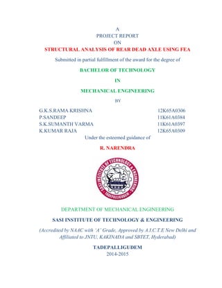
- 24. Structural Analysis of Rear Dead Axle by Using FEA 12 2.4.4 Cross Section of Axle The tandem axle consists of several cross sectional beams they are rectangular section, circular section, triangular section, I-beam section, H-beam section etc., In this project we are using I-section beam. 2.4.4.1 I-Section Beam: All standard axles have an I-cross section in the middle (spring seat to spring seat) and circular or elliptical cross sections at the ends. The axle beam will have I cross section in the middle and circular cross sections at the ends. An axle is usually a forged component for which a higher strength to weight ratio is desirable. The I-cross section has lower section modulus and hence gives better performance with lower weight. This type of construction produces an axle that is lightweight and yet has great strength. The I-beam axle is shaped so that the centre part is several inches below the ends. This permits the body of the vehicle to be mounted lower than it could be if the axle were straight. A vehicle body that is closer to the road has a lower centre of gravity and holds the road better. On the top of the axle, the springs are mounted on flat, smooth surfaces or pads. The mounting surfaces are called spring seats and usually have five holes. The four holes on the outer edge of the mounting surface are for the U-bolts which hold the spring and axle together. The centre hole provides an anchor point for the centre bolt of the spring. The head of the centre bolt, seated in the centre hole in the mounting surface, ensures proper alignment of the axle with the vehicle frame.
- 25. Structural Analysis of Rear Dead Axle by Using FEA 13 Fig.2.4.4.1 Rear Dead Axle
- 26. Structural Analysis of Rear Dead Axle by Using FEA 14 3. MATERIAL SELECTION 3.1 Introduction Materials science and engineering plays a vital role in this modern age of science and technology. Various kinds of materials are used in industry, housing, agriculture, transportation, etc. to meet the plant and individual requirements. The rapid developments in the field of quantum theory of solids have opened vastopportunities for better understanding and utilization of various materials. The spectacular success in the field of space is primarily due to the rapid advances in high-temperature and high- strength materials. The selection of a specific material for a particular use is a very complex process. However, one can simplify the choice if the details about (i) operating parameters, (ii) manufacturing processes, (iii) functional requirements and (iv) cost considerations are known. Factors affecting the selection of materials are summarized Table3.1 Factors effecting the selection of materials Manufacturing processes Functional requirements Cost considerations Operating parameters Plasticity Strength Raw material Pressure Malleability Hardness Processing Temperature Ductility Rigidity Storage Flow Machinability Toughness Manpower Type of material Casting properties Thermal conductivity Special treatment Corrosion requirements Weldability Fatigue Inspection Environment Heat Electrical treatment Packaging properties Protection from fire Tooling Creep Inventory Weathering Surface finish Aesthetic look Taxes and custom duty Biological effects There are thousands and thousands of materials available and it is very difficult for an engineer to possess a detailed knowledge of all the materials. However, a good grasp of the fundamental principles which control the properties of various materials help one to make the optimum selection of material. In this respect, materials science and engineering draw heavily from the engineering branches, e.g. metallurgy, ceramics and polymer science. The subject of material science is very vast and unlimited. Broadly speaking, one can sub-divide the fieldof study into following four branches:
- 27. Structural Analysis of Rear Dead Axle by Using FEA 15 (i) Science of metals, (ii) Mechanical behaviour of metals (iii) Engineering metallurgy (iv) Engineering materials 3.2 Engineering Requirements While selecting materials for engineering purposes, properties such as impact strength, tensile strength,and hardness indicate the suitability for selection but the design engineer will have to make sure that the radiography and other properties of the material are as per the specifications. One can dictate the method of production of the component, service life, cost etc. However, due to the varied demands made metallic materials, one may require special surface treatment, e.g. hardening, normalizing to cope with the service requires. Besides, chemical properties of materials, e.g. structure, bonding energy, resistance to environmental degradation also effect the selection of materials for engineering purposes. In recent years polymeric materials or plastics have gained considerable popularity as engineeringmaterials. Though inferior to most metallic materials in strength and temperature resistance, these are being used not only in corrosive environment but also in the places where minimum wear is required, e.g. small gear wheels, originally produced from hardened steels, now manufactured from nylon or Teflon. These materials perform satisfactorily, are quiet and do not require lubrication. Thus, before selecting a material or designing a component, it is essential for one to understand the requirements of the process thoroughly, operating limitations like hazardous or non-hazardous conditions, continuous or non-continuous operation, availability of raw materials as well as spares, availability of alternate materials life span of the instrument/equipment, cost etc. Different materials possess different properties to meet the various requirements for engineering purposes. The properties of materials which dictate the selection are as follows 3.2.1 Mechanical Properties: The important mechanical properties affecting the selection of a material are: a. Tensile Strength: This enables the material to resist the application of a tensile force. To withstandthe tensile force, the internal structure of the material provides the internal resistance. b. Hardness: It is the degree of resistance to indentation or scratching, abrasion and wear. Alloyingtechniques and heat treatment help to achieve the same. c. Ductility: This is the property of a metal by virtue of which it can be drawn into wires or elongatedbefore rupture takes place. It depends upon the grain size of the metal crystals.
- 28. Structural Analysis of Rear Dead Axle by Using FEA 16 d. Impact Strength: It is the energy required per unit cross-sectional area to fracture a specimen, i.e., a measure of the response of a material to shock loading. e. Wear Resistance: The ability of a material to resist friction wear under particular conditions, i.e. tomaintain its physical dimensions when in sliding or rolling contact with a second member. f. Corrosion Resistance: Those metals and alloys which can withstand the corrosive action of a medium i.e. corrosion processes proceed in them at a relatively low rate are termed corrosion-resistant. g. Density: This is an important factor of a material where weight and thus the mass is critical, i.e.aircraft components. 3.2.2 Thermal Properties: The characteristics of a material, which are functions of the temperature, are termed its thermal properties. One can predict the performance of machine components during normal operation, if he has the knowledge of thermal properties. Specific heat, latent heat, thermal conductivity, thermal expansion, thermal stresses, thermal fatigue, etc. are few important thermal properties of materials. These properties play a vital role in selection of material for engineering applications, e.g. when materialsure considered for high temperature service. Now, we briefly discuss few of these properties: a. Specific Heat (c): It is the heat capacity of a unit mass of a homogeneous substance. For a homogeneous body, c = C/M, where C is the heat capacity and M is the mass of the body. One can also define it as the quantity of heat required to raise the temperature of a unit mass of the substance through 1°C. Its units are Cal/g/°C. b. Thermal Conductivity (K): This represents the amount of heat conducted per unit time through a unit area perpendicular to the direction of heat conduction when the temperature gradient across the heat conducting element is one unit. Truly speaking the capability of the material to transmit heat through it is termed as the thermal conductivity. Higher the value of thermal conductivity, the greater is the rate at which heat will be transferred through a piece of given size. Copper and Aluminium are good conductors of heat and therefore extensively used whenever transfer of heat is desired. Bakelite is a poor conductor of heat and hence used as heat insulator.
- 29. Structural Analysis of Rear Dead Axle by Using FEA 17 Table 3.2.2 Thermal Conductivity for Materials Type of the material Material Thermal conductivity (K) (W/m/k) Metals Copper Aluminium Cast iron Mild steel Stainless steel 380 230 52 54 16 Ceramics Alumina 2.0 Titanium Carbide Glass 2.0 3.0 1.0 Polymers Bakelite 0.23 Composites Wood Concrete 1.4 0.14 c. Thermal Expansion: All solids expand on heating and contract on cooling. Thermal expansion may takeplace as linear, circumferential or cubical. A solid which expands equally in three mutually orthogonaldirections is termed as thermally isotropic. The increase in any linear dimension of a solid, e.g. length,width, height on heating is termed as linear expansion. The coefficient of linear expansionis the increasein length per unit length per degree rise in temperature. The increase in volume of a solid on heating iscalledcubical expansion. The thermal expansion of solids has its origin in the lattice vibration and lattice vibrations increases with the rise in temperature. d. Thermal Resistance (RT): It is the resistance offered by the conductor when heat flow due to temperature difference between two points of a conductor. e. Thermal Diffusivity (h): A material having high heat requirement per unit volume possesses a low thermal diffusivity becausemore heat must be added to or removed from the material for effecting a temperature change. f. Thermal Fatigue: This is the mechanical effect of repeated thermal stresses caused by repeated heatingandcooling.The thermal stresses can be very large, involving considerable plastic flow. We can see that fatiguefailures can occur after relatively few cycles. The effect of the high part of the temperature cycle on thestrength of material plays an important factor in reducing its life under thermal fatigue. 3.2.3 Electrical Properties: Conductivity, resistivity and dielectric strength are few important electrical properties of a material. A material which offers little resistance to the passage of an
- 30. Structural Analysis of Rear Dead Axle by Using FEA 18 electric current is said to be a good conductor of electricity. The electrical resistance of a material depends on its dimensions. Usually resistivity of a material is quoted in the literature. Unit of resistivity is Ohm-meter. On the basis of electrical resistivity materials are divided as Conductors, Semiconductors and Insulators. In general metals are good conductors. Insulators have very high resistivity. Ceramic insulators are most common examples and are used on automobile spark plugs, Bakelite handles for electric iron, and plastic coverings on cables in domestic wiring. When a large number of metals and alloys are sufficiently cooled below transition temperature, Tcenterthe state of superconductivity in which the dc resistivity goes to zero. The highest value of Tcup to 133 K has been reached for mercury curate. 3.2.4 Magnetic Properties: Materials in which a state of magnetism can be induced are termed magneticmaterials. There are five classes into which magnetic materials may be grouped: (i) Diamagnetic (ii) Paramagnetic (iii) Ferromagnetic and (iv)Anti ferromagnetic Iron, Cobalt, Nickel and some of their alloys and compounds possess spontaneous magnetization. Magnetic oxides like ferrites and garnets could be used at high frequencies. Because of their excellent magnetic properties along with their high electrical resistivity these materials today find use in a variety of applications like magnetic recording tapes, inductors and transformers, memory elements, microwave devices, bubble domain devices, recording hardcore’s, etc. Hysteresis, permeability and coercive forces are some of the magnetic properties of magnetic substances which are to be considered for the manufacture of transformers and other electronic components. 3.2.5 Chemical Properties: This property includes atomic weight, molecular weight, atomic number,valence, chemical composition, acidity, alkalinity, etc. These properties govern the selection of materials particularly in Chemical plant. 3.3 Structure of Materials The properties of engineering materials mainly depend on the internal arrangement of the atoms on molecules. We must note that in the selection of materials, the awareness regarding differences and similarities between materials is extremely important.
- 31. Structural Analysis of Rear Dead Axle by Using FEA 19 Metals of a single type atom are named pure metals. Metals in actual commercial use are almost exclusively alloys, and not pure metals, since it is possible for the designer to realize an infinite variety of physical properties in the product by varying the metallic composition of the alloy. Alloys are prepared from mixed types of atoms. Alloys are classified as binary alloys, composed of two components, as ternary alloys, composed of three components or as multi component alloys. Most commercial alloys are multi component. The composition of an alloy is described by giving the percentage (either by weight or by atoms) of each element in it. The basic atomic arrangement or pattern is not apparent in the final component, e.g. a shaft or a pulley but the properties of the individual crystals within the metallic component, which are controlled by the atomic arrangement, are mainly responsible for their application in industry. One can determine the strength of a piece of metal by its ability to withstand external loading. The structure of metal or alloy responds internally to the applied load by trying to counteract the magnitude of the applied load and thus tries to keep the constituent atoms in their ordered positions if however the load is higher than the force which holds the atoms in place, the metallic bond becomes ineffective and atomsin the metal are then forced into new displaced positions. The movement of atoms from their original positions in the metal is termed as slip.The ease with which atoms move or slip in a metal is an indication of hardness. We must note that the relative movement of atoms or slip within a material has a direct bearing on the mechanical properties of the material. 3.4 Classification of Engineering Materials The factors which form the basis of various systems of classifications of materials in material science and engineering are (i)the chemical composition of the material, (ii)the mode of the occurrence of the material in the nature, (iii) the refining and the manufacturing process to which the material is subjected prior it acquires the required properties, (iv) the atomic and crystalline structure of material and (v)the industrial and technical use of the material. Common engineering materials that fall within the scope of material science and engineering may beclassified into one of the following six groups: a. Metals (ferrous and non-ferrous) and alloys b. Ceramics c. Organic Polymers d. Composites e. Semi-conductors
- 32. Structural Analysis of Rear Dead Axle by Using FEA 20 f. Biomaterials g. Advanced Material 3.4.1 Metals: All the elements are broadly divided into metals and non-metals according to their properties.Metals are element substances which readily give up electrons to form metallic bonds and conduct electricity.Some of the important basic properties of metals are: (a) metals are usually good electrical andthermal conductors, (b) at ordinary temperature metals are usually solid, (c) to some extent metals aremalleable and ductile, (d) the freshly cut surfaces of metals are lustrous, (e) when struck metal producetypical sound, and (f) most of the metals form alloys. When two or more pure metals are melted together to form a new metal whose properties are quite different from those of original metals, it is called an alloy. Metallic materials possess specific properties like plasticity and strength. Few favorable characteristicsof metallic materials are high luster, hardness, resistance to corrosion, good thermal and electrical conductivity, malleability, stiffness, the property of magnetism, etc. Metals may be magnetic, non-magnetic innature. These properties of metallic materials are due to: (i) the atoms of which these metallic materials arecomposed and (ii) the way in which these atoms are arranged in the space lattice. Metallic materials are typically classified according to their use in engineering as under: (i) Pure Metals: Generally it is very difficult to obtain pure metal. Usually, they are obtained by refiningthe ore. Mostly, pure metals are not of any use to the engineers. However, by specialized and very expensivetechniques, one can obtain pure metals (purity ~ 99.99%), e.g. aluminum, copper etc. (ii) Alloyed Metals:Alloys can be formed by blending two or more metals or at least one being metal. Theproperties of an alloy can be totally different from its constituent substances, e.g. 18-8 stainless steel, whichcontains 18%, chromium and 8% nickel, in low carbon steel, carbon is less than 0.15% and this is extremelytough, exceedingly ductile and highly resistant to corrosion. We must note that these properties are quitedifferent from the behavior of original carbon steel. (iii)Ferrous Metals:Iron is the principal constituent of these ferrous metals. Ferrous alloys contain significantamount of non-ferrous metals. Ferrous alloys are extremely important for engineering purposes. On thebasis of the percentage of carbon and their alloying elements present, these can be classified into followinggroups:
- 33. Structural Analysis of Rear Dead Axle by Using FEA 21 (a) Mild Steels:The percentage of carbon in these materials range from 0.15% to 0.25%. These are moderately strong and have good weld ability. The production cost of these materials is also low. (b) Medium Carbon Steels:These contains carbon between 0.3% to 0.6%. The strength of these materials is high but their weld ability is comparatively less. (c) High Carbon Steels:These contains carbon varying from 0.65% to 1.5%. These materials get hardened tough by heat treatment and their weld ability is poor.The steel formed in which carbon content is up to 1.5%, silica up to 0.5%, and manganese up to 1.5%alongwith traces of other elements is called plain carbon steel. (d) Cast Irons:The carbon content in these substances varies between 2% to 4%. The cost of productionofthese substances is quite low and these are used as ferrous casting alloys. (iv) Non-Ferrous Metals:These substances are composed of metals other than iron. However, thesemaycontain iron in small proportion. Out of several non-ferrous metals only seven are available in sufficientquantity reasonably at low cost and used as common engineering metals. These are aluminum, tin, copper, nickel, zinc and magnesium. Some other non-ferrous metals, about fourteen in number, are produced inrelatively small quantities but these are of vital importance in modern industry. These include chromium,mercury, cobalt, tungsten, vanadium, molybdenum, antimony, cadmium, zirconium, beryllium, niobium,titanium, tantalum and manganese. (v) Sintered Metals:These materials possess very different properties and structures as compared to themetals from which these substances have been cast. Powder metallurgy technique is used to produces interred metals. The metals to be sintered are first obtained in powered form and then mixed in rightcalculated proportions. After mixing properly, they are put in the die of desired shape and then processedwith certain pressure. Finally, one gets them sintered in the furnace. We must note that the mixture soproduced is not the true alloy but it possesses some of the properties of typical alloys. (vi) Clad Metals:A sandwich of two materials is prepared in order to avail the advantage of the propertiesof both the materials. This technique is termed as cladding. Using this technique stainless steel is mostlyembedded with a thick layer of mild steel, by rolling the two metals together while they are red hot. Thistechnique will not allow corrosion of one surface. Another example of the use of this technique is claddingof duralumin with thin sheets of pure aluminum. The surface layers, i.e. outside layers
- 34. Structural Analysis of Rear Dead Axle by Using FEA 22 of aluminum resistcorrosion, whereas inner layer of duralumin imparts high strength. This technique is relatively cheap tomanufacture. Table3.4.1 Important grouping of Materials Material group Important characteristics Typical examples of engineering use 1. Metals and Alloys Lustre, hardness, thermal and electrical conductivity, resistance to corrosion, malleability, stiffness and the property of magnetism Iron and steels, aluminium, copper, silver, gold, zinc, magnesium, brasses, bronzes, Manganin, invar, super alloy, boron, rare-earth alloys, conductors, etc. 2. Ceramics and Glasses Thermal resistance, hardness, brittleness, opaqueness to light, electrical insulation abrasiveness, high temperature strength and resistance to corrosion Silica, soda-lime-glass, concrete, cement, refractory’s, Ferrites and garnets, ceramic superconductors, MgO, CdS, Al2O3, SiC, BaTiO3, etc 3. Organic Polymers Soft, light in weight, poor conductors of electricity and heat, dimensionally unstable, ductile, combustible, low thermal resistance Plastics:PVC, PTFE, polyethylene, polycarbonate Fibres:terylene, nylon, cotton, natural and synthetic rubbers, leather Other uses:refrigerants, explosives, insulators, lubricants, detergents, fuels, vitamins, medicines for surface treatment, adhesives, fibre-reinforced plastics, etc. Composites (i) Metals and alloys and ceramics (ii) Metals and alloys and organic polymers (iii) Ceramics and organic polymers They are better than any of the individual components as regards to their properties like strength, stiffness, heat resistance, etc. Steel-reinforced concrete, dispersion hardened alloys. Vinyl coated steel, whisker reinforced Plastics. Fibre-reinforced plastics, Carbon-reinforced rubber.
- 35. Structural Analysis of Rear Dead Axle by Using FEA 23 Table3.4.1.2 Properties for Grouping of Materials Property Metals Ceramics Polymers Composites (wood) 1.Tensilestrength (N/mm2 ) 200–2000 10–400 30–100 20–110 2.Density (10N/mm2 ) 2–8 *10e3 2–17 * 10e3 1–2 * 10e3 0.5 * 10e3 3. Hardness Medium High low low 4.Tensilemodulus (103N/mm2 ) 100–200 150–450 0.7–3.5 4–20 5. Melting point (°C) 200–3500 2000–4000 70–200 — 6. Thermal expansion Medium Low High Low 7.Thermal conductivity High Medium Low Low 8.Electrical conductivity Good conductor Insulator Insulator Insulator 3.4.2 Engineering Metallurgy: This includes the study of metallurgy, which is of special interest to an engineer. At the time of taking final decision regarding the selection of suitable material for a particular job, it is essential for an engineer to have a thorough knowledge of engineering metallurgy. This helps him in deciding the treatment processes and their sequence, which are to be carried out on the finished components and structures. This includes the following processes: (i) Iron-carbon alloy system: This deals with the structure of iron and steel as well as iron-carbon equilibrium diagrams. This also deals with the transformation of alloys and steels under various sets of condition. A detailed and thorough study of this process helps an engineer to decide the suitability of process and the selection of iron alloy for various types of his jobs. (ii) Heat Treatment: A thorough knowledge of this helps an engineer in deciding the type of process to be undertaken for the smooth and efficient working of the components and structures. (iii) Corrosion of Metals:This deals with the colossal problem of corrosion of metals and its prevention. It also deals with the processes which help engineers in improving the life and outward appearance of themetal components and structures.
- 36. Structural Analysis of Rear Dead Axle by Using FEA 24 3.5 Selection of Materials One of the most challenging task of an engineer is the proper selection of the material for a particular job,e.g., a particular component of a machine or structure. An engineer must be in a position to choose the optimum combination of properties in a material at the lowest possible cost without compromising the quality. The properties and behavior of a material depends upon the several factors, e.g., composition, crystal structure, conditions during service and the interaction among them. The performance of materials may be found satisfactory within certain limitations or conditions. However, beyond these conditions, the performance of materials may not be found satisfactory. One can list the major factors affecting the selection of materials as i. Component shape ii. Dimensional tolerance iii. Mechanical properties iv. Fabrication requirements v. Service requirements vi. Cost of the material vii. Cost of processing, and viii. Availability of the material. All these major factors have a complex effect on the selection of materials. The shape and size of a component has great effect on the choice of the processing unit which ultimately affects the choice of themat serial even the efficient utilization of materials. In this project we are using the two materials from the ferrous alloys (i) Ductile cast iron (ii) High grade 3.5.1 Ductile Cast Iron: 3.5.1.2Chemical Composition: Nodular cast iron of high strength. GGG-70: Ferro (Fe) rest, Carbon (C) 3.0, Silicon (Si) 2.40, Manganese (Mn) 0.50, Chromium (Cr) 0.50 (wt%)
- 37. Structural Analysis of Rear Dead Axle by Using FEA 25 3.5.1.3Mechanical properties: Table3.5.1.3Mechanical properties for DCI 3.5.1.4 Thermal properties: Table3.5.1.4Thermal properties for DCI Minimum value Maximum value Units Melting temperature 1150 1250 °C Service temperature -100 350 °C Thermal conductivity 25 42 W/mK Thermal expansion 10 13 K 3.5.2 High Grade Steel: 3.5.2.1 Chemical Composition: 14NiCr14: Ferro (Fe) rest, Carbon (C) 0.11-0.17, Nickel (Ni) 3.25-3.75, Chromium (Cr) 1.25-1.75, Silicon (Si) 0.17-0.37, Manganese (Mn) 0.30-0.60. Minimum value Maximum value Unit Density 7100 7300 kg/m³ Elongation 1 2 % Tensile strength 650 700 MPa Yield strength 380 400 MPa Young's modulus 177000 185000 MPa
- 38. Structural Analysis of Rear Dead Axle by Using FEA 26 3.5.2.2 Mechanical properties: Table3.5.2.2 Mechanical properties for HGS Minimum value Maximum value Units Density 7860 7860 kg/m³ Elongation 1 2 % Tensile strength 1100 1400 MPa Yield strength 300 400 MPa Young’s modulus 203000 203000 MPa 3.5.2.3 Thermal properties: Table3.5.2.3Thermal properties for HGS Minimum value Maximum value Units Melting temperature 1540 1540 °C Specific heat 500 500 J/kgK Thermal conductivity 40 40 W/mK Thermal expansion 12 12 K
- 39. Structural Analysis of Rear Dead Axle by Using FEA 27 4. SOLID WORKS 4.1 Introduction SolidWorks is the state of the art in computer-aided design(CAD). SolidWorksrepresents an object in a virtual environment just as it exists in reality, i.e., having volume as well as surfaces and edges. Complex three-dimensional parts with contoured surfaces and detailed features can be modeled quickly and easily with SolidWorks. Then, many parts can be assemblingdin virtual environment to create a computer model of the finished product. In addition, traditional engineering drawings can be easily extracted from the solidmodels of both the parts and the final assembly. This approach opens the door to innovative design concepts, speeds product development, and minimizes design errors. The result is the ability to bring high-quality products to market very quickly. Solid modeling represents objects in a computer as volumes, rather than just as collections of edges and surfaces. Features are three-dimensional geometries with direct analogies to shapes that can be machined or manufactured, such as holes or rounds. Feature-based solid modeling creates and modifies the geometric shapes of an object in a way that represents common manufacturing processes. This makes SolidWorksa very powerful and effective tool for engineering design. As with other computer programs, SolidWorks organize and stores data in files. Each file has a name followed by a period(dot) and an extension. There are several file types used in SolidWorks, but the most common file types and their extension sore Part files .prt or ldprt Assembly files .asmor.sldasm Drawing files .drw or .slddrw a. Part files:The files are the individual parts that are modeled. Part files contain all of the pertinent information about the part. Because SolidWorks is a solids-modeling program, the virtual part on the screen will look very similar to the actual manufacture part. b. Assembly files:These files created from several individual part files that are virtually assembled(in the computer) to create the finished product. c. Drawing files:Thetwo dimensional engineering drawing representations of both the part and assembly file. The drawings should contain all of the necessary information for the manufacture of the part, including dimensions, part tolerances, and so on. The part file is the driving file for all other file types. The modeling procedure begins with Part files. Subsequent assemblies and drawings are based on the original part files. One advantage of SolidWorksfiles is the feature of dynamic links. Any change to apartfile will automatically be updated in any corresponding
- 40. Structural Analysis of Rear Dead Axle by Using FEA 28 assembly or drawing file.Therefore, both drawing and assembly files must be able to find and access their corresponding partfiles in order to be opened. SolidWorks uses information embedded within the file and the filename to maintain these links automatically. 4.2 Starting Solid Works SolidWorks runs on computers running the Microsoft Windows operating system.You open Solid Works in the same way that you would start any other program. 4.2.1 CheckingtheOptionsSettings: TheSolidWorkswindow that appears on the computer screen looks similar to the standard Microsoft Windows interface. The top line of the window is the Menu bar from which menus for various operations can be opened. Below the Menu bar are the toolbars which provide access to a variety of commonly used operations, ortools, with a single click of the mouse button. Toolbars can also extend down the right and left sides of the window. They may or may not be shown on your screen. At this point, most items within the toolbars are grayed out. This indicates that they are not presently available for use. The main part of the window is the Graphics Window. This is where the model is displayed. Just below the Graphics Window is the Status bar, which displays information about the current operation. The Status bar should now indicate “Ready”, since SolidWorks is ready to proceed. Fig.4.2.1SolidWorks window Before you begin a sketch you need to setup some appropriate options. These setting may be changed according to your needs.
- 41. Structural Analysis of Rear Dead Axle by Using FEA 29 1. If the Welcome to SOLIDWORKSdialogue box is open, close it by clicking on the Xin it super right corner. 2. Click Tools in the Menu bar. Next, select Options(that is, Tools⇒Options). 3. The System Options dialogue box appears with the System Options tab visible. 4. Reset all of the preferences to the factory default by clicking Reset All followed by Yesin the confirmation dialog box. 5. Click on the check mark next to input dimension value to remove the check mark. This changes the way that dimensions are added to sketches. Click OK to close the dialogbox. Fig.4.2.1.1 System Option dialog box 4.2.2 General Toolbars: To specify which toolbars are displayed on the screen, select View Tool- bars(i.e.,selectToolbars from the View menu). Be sure that the Features, Sketch, SketchRelations, SketchTools, Standard, StandardViewsand View toolbars are checked. If they are not, click on each of these items until all are checked. If other toolbars are checked, click on them to uncheck them. It may be necessary to select View, then Toolbars again to display them after checking(run-checking) an item to confirm that the desired change was made. The Standard Views toolbar may appear as a dialogboxin the Graphics Window instead of as a toolbar. If so, click the blue bar at the top of the dialogbox with the left mouse button and drag it to the toolbar at the upper right of the Graphics Window. Release the mouse button. The dialogbox should change to a toolbar.
- 42. Structural Analysis of Rear Dead Axle by Using FEA 30 Fig.4.2.2 Toolbar Menu The Sketch toolbar contains tools to set up and manipulate a sketch. The Sketch Tools toolbar contains tools to draw lines, circles, rectangles, arcs, and so on. The Sketch Relations toolbar contains tools for constraining element sofa sketch by using dimensions or relations. The Features toolbar contains tools that modify sketches and existing features of a part. The Standard tool bar contains the usual commands available for manipulating files, editing documentsand accessing Help. The Standard Views toolbar contains common orientations for a model. TheViewtoolbar contains tools to orient and rescale the view of a part. You can find these toolbars around the Graphics Window by checking and un-checking in the View⇒Toolbarsmenu. The toolbars will appear as you check them and disappear you uncheck them. Currently, most of the items in the tool-bars are grayed out, since they are unusable. They will become active when they are available for use.Be sure that the Toolbars menu looks like the one before continuing. Click any open spot in the Graphics Window to close all menus. 4.3 Creating a New Part With the SOLID WORKS window open, select File⇒Newin the Menubar, or click the New button(a blank-sheet icon) in the Standard toolbar.
- 43. Structural Analysis of Rear Dead Axle by Using FEA 31 The New SOLID WORKS Document dialogboxappears. You will be modelling a new part. If Part is already highlighted, clickOK. If it is not highlighted, click Part,thenOK. Fig.4.3 New document window 4.4 Sketching Every part begins as a cross section sketched on a two-dimensional plane. Once a sketch is made, it is extruded or revolved into the thirddimension to create a three- dimensional object.This is the base feature of the part. The Sketch toolbar has tools to setup and manipulate a sketch of a cross section. Find the Sketch toolbar. Move the cursor over each of the tools, but donotclick on any of the tools. The Tool Tips should appear, displaying the name of each tool. Select highlights sketch entities drags sketch entities and endpoints and Modifies dimension values. Grid activates the Grid/Snap field of the Document Properties dialogue box to change the sketching environment. Dimension adds dimensions to sketch entities. Sketch opens and closes sketches as a part is created. To set the units and grid size to be used, click the Grid toolbar button with the left mouse button. Document properties dialogue box will appear. Click Units on the left side of the dialogue box to set the units. Setup appropriate units(inches or mm) with the desired number of decimal places or fraction denominator.
- 44. Structural Analysis of Rear Dead Axle by Using FEA 32 Click Grid/Snap on the left side of the dialogue box to control the grid that will appear on the screen when a cross-section is sketched. Be sure that all three of the boxes under Gridare checked. Adjust the grid spacing to desiredvalues. Snap controls the way in which sketched lines are related to the grid. The points that are sketched should “snap” to the nearest intersection of gridlines when they are close. Be sure the Snap to point’s box is checked. If not, click the box to check it. Click Detailing on the left side of tile dialogue box. If necessary, change Dimensioning standard to ANSI for inch units and ISO in case of mm units. Then, click OK at the bottom of the dialogue box to accept the values. Open a new sketch by selecting Insert Sketch, or by clicking the Sketch button(a pencil drawing a line) in the Sketch tool bar. A grid should appear on the screen, indicating that the sketch mode is active. The window’s name changes to Sketch of Part1. In the bottom right corner of the screen, the Status bar reads Editing Sketch. You are now ready to sketch in the Front plane. The Sketch Tools toolbar contains tools to create and modify two- dimensional features, called Sketch Entities. Sketch Entities are items that can be drawn on the sketch. The following Sketch Entities and Sketch Tools are available Line creates a straight line. Center point Arc creates a circular arc from a center point, a start point, and an end point. Tangent Arc creates a circular arc tangent to an existing sketch entity. 3 Pt Arc creates a circular arc through three points. Circle creates a circle. Spline creates a curved line that is not a circular arc. Polygon creates a regular polygon. Rectangle creates a rectangle. Point creates a reference point that is used for constructing other sketch entities. Centerline creates a reference line that is used for constructing other sketch entities. Convert Entities creates a sketch entity by projecting an edge, curve, or contour onto the sketch plane. Mirror reflects entities about a center line. • Fillet creates a tangent arc between two sketch entities by rounding an inside or an outside corner. • Offset Entities creates a sketch curve that is offset from a selected sketch entity by a specified distance. • Trim removes a portion of a line or curve.
- 45. Structural Analysis of Rear Dead Axle by Using FEA 33 • Construction Geometry creates entities that aid in sketching. • Linear Sketch Step and Repeat creates a line and pattern of sketch entities. • Circular Sketch Step and Repeat creates a circular pattern of sketch entities. Move and hold the cursor over each of the tools to display its function but donotclick on the tool. Note the description of each tool in the Status bar at the bottom of the SolidWorks window. Some of these tools may not include in the toolbar or other tools may be available, depending on the way in which it was previously setup. All tools are available in the Tools Menu.
- 46. Structural Analysis of Rear Dead Axle by Using FEA 34 5. FINITE ELEMENTANALYSIS 5.1 Introduction The finite element method represents an extension of the matrix method for the analysis of framed structures to the analysis of the continuum structures. The basic philosophy of the method is to replace the structure of the continuum having an unlimited or infinite number of unknowns at certain chosen discrete points. The method is extremely powerful as it helps to accurately analyze structures with complex geometrical properties and loading conditions. In the infinite method, a structure or continuum is discretized and idealized by using a mathematical model which is an assembly of subdivisions or discrete elements, known as finite element, are assumed to be interconnected only at the joint called nodes. Simple functions such as polynomials are chosen in terms of unknown displacements at the nodes to approximate the vibrations of the actual displacement over each finite element. The external loading is also transformed into equivalent forces applied at the nodes. Next, the behavior of each element independently and later as an assembly of these elements is obtained by relating their response to that of the nodes in such a way that the following basic conditions are satisfied at each nodes: Equations of equilibrium The compatibility of displacements The material constitutive relationship The equations, which are obtained using the above conditions, are in the form of force-displacement relationship. Finally, the force-displacement equations are solved to obtain displacement at the nodes, which are the basic unknown in the finite element method. The basic idea in the finite element method is to find solution of a complicated problem by replacing it by simpler one. Since a simpler one in finding the solution replaced the actual problem, we will be able to find only an approximate solution rather than exact solution. In finite element method, it will often be possible to improve or refine the approximate solution by sending more computational effort. This is a numerical solution for obtaining solutions to many of the problems encountered in engineering analysis. In this method, the body or the structure may be divided into small element of finite dimensions called finite element. The original body or continuum is then considered as assemblage of these elements connected at a finite number of joint called nodes.
- 47. Structural Analysis of Rear Dead Axle by Using FEA 35 5.2 Boundary Conditions of Fem The general nature of its theory makes it applicable to a wide variety of boundary value problems in engineering. A boundary values problems is one of which a solution is sought in domain (region) of a body subject to the satisfaction of the prescribed boundary (edge) condition of the dependent variable of their derivatives. Mostly all engineering problems which are illustrated in the table 5.2 of the finite element method comes under three categories of boundary problems, namely 1. Equilibrium or steady state or time independent problem, 2. Eigen value problem, 3. Transient or propagation problem. Table 5.2 various applications of finite element analysis Area of study Equilibrium problems Eigen value problems Propagation problems 1.Civil engineering structures Static analysis of the trusses, frames, folded plates, roofs, shear walls Natural frequencies and nodes structures Propagation of stress waves 2.Aircraft structures Static analysis of wings, rockets, fuselages, fins and missile structures Natural frequencies flutter and stability of aircraft, rocket. Response of aircraft structures to random loads, dynamic response of aircraft. 3.Hydraulic and water resources engineering Analysis of potential flows, free surface flows, viscous flows. Natural periods and modes of shallow basins, lakes and harbours Analysis of unsteady state fluid flow and wave propagation problems 4.Nuclear engineering Analysis of nuclear pressures vessel and containment structures Natural frequencies and stability of containment structures Response of reactor containment structures to dynamic loads. 5.Mechanical design Stress concentration problems, stress analysis of pressure vessel, pistons, gears. Natural frequencies and stability of linkages, gears and machine tools. Crack and fracture problems under dynamic loads.
- 48. Structural Analysis of Rear Dead Axle by Using FEA 36 5.3 General Description of Fem The step by step procedure for static problem can be stated as follows: Step 1: Discretization of continuum The first step in the finite element is to divide the structure of solution region into sub division of element. The sub division or discretization process of the continuum is essentially an exercise of engineering judgment. These subdivisions are called elements, and are connected to the adjacent of the elements in such a way that the original body is represented by it as closely as possible. Hence, the general objective of such an idealization is to discretize the body into finite number of elements sufficiently small so that the simple displacement models can adequately approximate the true solution. Step 2: Selection of proper interpolation model Since the displacement (field variable) solution of the complex structure under any specific load condition cannot be predicted exactly, we assume some suitable with in an element to approximate the unknown solution. The assumed solution must be from computational point of view and it should satisfy certain convergence requirements. Step 3: Derivative of element stiffness matrices (Characteristics matrices) and load2 vectors From the assumed displacement model the stiffness matrix {K(e)} and load P(e) of the element ‘e’ are to be divided by using either equilibrium conditions or a suitable variation principle. Step 4: Assemblage of element equation to obtain the overall equilibrium equation Since the structure is compared of several finite elements, the individual element stiffness matrices and load vectors are to be assembled in a variable manner and the overall equilibrium equations have to be formulated as: [K] {d}=[P] Where [K] is called assemblage stiffness matrix, {d} is called nodal displacement vector and P is called nodal vector for the complete structure
- 49. Structural Analysis of Rear Dead Axle by Using FEA 37 Step 5: Solution of system equation to find nodal values of the displacement (fixed variable): The overall equation have to be modified, account for the boundary conditions of the problem, after the incorporation of the boundary conditions, the equilibrium equation are solved. 5.3.1 Type of Elements: Often the type of element to be used is evident from the problem itself. For example, if the problem involves the analysis of the truss structure under a given set of load conditions, the type of element to be used idealization of obviously the “the bar or line element”. However, in some cases the type of the elements to be used for idealization may not be appropriate and in such cases one has to choose the type of elements judicially. In certain problem, the given body cannot be represented as an assemblage of only one type of elements. In such cases we may have to use two or more types of element idealization. 5.3.2 Number of Elements: The number of elements to be chosen for idealization is related to the accuracy desired, size of element and the number of degrees of freedom involved. Although an increase in number of elements generally gives more accurate results, for any given problem, there will be certain number of elements reaching the point, where no significant improvement will be found. Moreover, since the use of large number of elements involves large number of degrees of freedom, we may not be able to store the resulting matrices in the available computer memory. 5.3.3 Size of Elements: The size of elements influences the convergence of the solution directly and it has to be chosen with a care. If the size of elements is small, the final solution is expected to the more accurate. However, we have to remember that the use of element of smaller size will also mean more complicated time. Sometimes, we may have to use the elements of different sizes in the same body. Another characteristic related to the size of element, which affects the finite element solution is the “aspect ratio” of the element. The aspect ratio is taken as the ratio of the element largest dimension to the smallest dimension of the element. Element with aspect ratio of nearly unity generally yield better results. a. Convergence Requirements: Since the finite element method is a numerical technique, we obtain a sequence of approximate solution as the element size is reduced successively. The sequence will converge to the exact solution if the interpolation polynomial satisfies the following requirements.
- 50. Structural Analysis of Rear Dead Axle by Using FEA 38 1. The displacement function must be continuous with in elements. 2. The displacement function must be capable of representing rigid body displacement of the element. 3. The displacement function must be capable of representing strain states within the element. b. Nodal Degrees of Freedom:The basic idea of FEM is to consider a body as composed to several elements, which is connected at a specific node points. The unknown solution or the field variables (like displacement, pressures or temperatures) any finite element is assumed to be given by a simple function in terms of nodal values of the elements. The nodal displacement, rotations, necessary to specify completely the deformation of the finite elements is the degree of freedom of the element. The nodal values of the solution, also known as nodal degree of freedom, are treated as unknowns in formulating the system of overall equations. The solutions of the system equation (like force equilibrium equations) gives the value of unknown nodal degrees of freedom. Once, the nodal degrees of freedom are known, the solution within any elements will also be known to us. For having the results in terms of nodal degrees of freedom of interpolation of function must be derived in terms of nodal degrees of freedom c. Assembly Of Element Equations:Once the elements characteristics, namely the element matrices and element vectors are found in a global co-ordinate system, the next step is to construct the overall or system equations. The procedure of assembling the elements matrices and vectors is based on the requirement of “Compatibility” at the element nodes. This means that at the nodes where elements are connected, the values of unknown degrees of freedom of the variables are same for all the elements at the nodes. d. Incorporation of the boundary conductions:After assembling the characteristic matrices [K(e)] and elements characteristic vectors P(e) the overall system equation of the entire domain of the body can be written (for any equilibrium problems) as, [K] {∅ ] = {P} These equations cannot be solved for {∅} since the matrix [K] will be singular and hence its inverse does not exist. The physical significance of this, in case of solid mechanics problems, is that the loaded body or structure is free to undergo unlimited rigid body motion unless some support constraints are imposed to keep the body or structure under equilibrium under the loads. Hence some boundary or support conditions have to be applied before solving for {∅}. In non structural problems we have to specify one or some times more than one nodal degree of freedom. The number of degrees of freedom is dictated by the physics of the problem.
- 51. Structural Analysis of Rear Dead Axle by Using FEA 39 5.4 Finite Element Analysis Finite element analysis was first developed for the use of aerospace and nuclear industries where the safety of structure is critical. Today growth in the usage of method is directly attributable to the rapid advances in computer technology. As a result commercial finite element packages exist that are capable of solving the most sophisticated problems, not just in structural analysis, but for a wide range of phenomena such as steady state and dynamic temperature distributions, fluid flow and manufacturing processes such as injection molding and metal forming. FEM is used in a new product design, and existing product refinement. Modifying an existing product or structure is utilized to qualify the product or structure for a new service condition. In case of structure failure, finite element analysis may be used to help in determining the design modifications to meet the new conditions. 5.4.1 Types of Analysis: There are different types of analysis that are used in a industry are Structural, Model, Harmonic, Transient and Spectrum 5.4.1.1 Structural Analysis: It consists of linear and non-linear models. Linear models are simple parameters and assume that material is not plastically deformed. Non-linear models consist of stressing the material past its elastic capabilities. The stresses in the material then vary with the amount of deformation. 5.4.1.2 Vibration Analysis: Itis used to test the material against random vibrations, shock and impact. Each of these incidents may act on the natural vibration frequency of the material, which in turn, may cause resonance and subsequent failure. So analysis is done on the material to predict the life of the material. Heat-Transfer analysis models the thermal conductivity or thermal fluid dynamics of the material or structure. This may consists of steady state or transient transfer. Steady-State transfer refers to constant thermo properties in material that yield linear heat diffusion. 5.5 Finite Element Analysis Process The structure analyzed is subdivided into mesh of finite sized elements of a simple shape. Within each element, the variation of displacement is assumed to be determined by simple polynomial shape functions and nodal displacements. Equations for strain and stresses are developed in terms of unknown nodal displacements. From this, the equations of equilibrium are assembling in a matrix form, which can be easily
- 52. Structural Analysis of Rear Dead Axle by Using FEA 40 programmed and solved, on a computer. After applying appropriate boundary conditions, the nodal displacements are found by solving the matrix stiffness equation. Once the nodal displacements are known element stresses and strains can be calculated 5.6 Introduction to Ansys Software The purpose of a finite element analysis is to model the behavior of a structure under a system of loads. In order to do so, all influencing factors must be considered and determined whether their effects are considerable or negligible on the final result. Muchsoftware’s are used for this purpose. ANSYS, Pro-E, Uni Graphics, NISA, MSC, NASTRAN etc, The ANSYS program this self-contained general purpose finite element program developed and maintained by Swanson Analysis System Inc. The program contains many routines, all interrelated and all for many purpose of achieving a solution to an engineering problem by Finite Element Method. ANASYS provides a complete solution to design problems. It consists of powerful design capabilities like full parametric solid modeling, design optimization and auto meshing, which gives engineers full control over their analysis. The following are the special features of ANSYS software: It includes bilinear elements. Heat flow analysis, fluid flow and element flow analysis can be done. Graphic package and extensive pre-processing and post processing. The following shows the brief description of steps followed in each phase.
- 53. Structural Analysis of Rear Dead Axle by Using FEA 41 5.6.1 Various Stages of Ansys: Table5.6.1 Stages of Ansys 5.6.2 Pre-Processor: The pre-processor stage in ANSYS package involves the following: Specify the title, which is the name of the problem. Set the type of the analysis to be used, i.e., structural, thermal, fluid, or electro- magnetic, etc., Create the model - The model is drawn in 1-D, 2-D, or 3-D space in the appropriate units (m, mm, in, etc). The model may be created in pre-processor, or it can be imported from another CAD drafting package through a neutral file format9 like IGES, STEP, ACIS, Para solid, DFX, etc.,. The same units should be applied in all directions, otherwise results will be difficult to interpret, or in extreme cases the result will not show up mistakes made during loading and restraining of the model. Define the element type, this may be 1D, 2D or 3D, and specify the analysis type being carried out. Apply mesh - Mesh generation is the process of dividing the analysis continuum in to a number of discrete parts or finite elements. The finer mesh, the better result, but the longer the analysis time. Therefore, the compromise between accuracy and solution speed is usually made. Pre-Processor Phase Solution Phase Post Processor Phase Geometry definitions Element matrix formation Post solution operation Mesh generation Overall matrix triangulation Post data print out Materials definition Wave front Post data display Constraint definition Displacement, Stress, etc., Load definition Calculations
- 54. Structural Analysis of Rear Dead Axle by Using FEA 42 Assign the properties - Material properties (Young's Modulus, Poisson's ratio, density, and if applicable coefficient of expansion, friction, thermal conductivity, damping effect, specific heat, etc.,) have to be defined. 5.6.3 Meshing: 5.6.3.1 Manual Meshing: In manual meshing the elements are smaller at joint. This known as mesh refinement, and it enables the stress to be captured at the geometric discontinuity. Manual meshing is long and tedious process for models with any degree of geometric complication, but with useful tool emerging in preprocesses, the task is becoming easier Free and Mapped Mesh:A free mesh is one that has no restrictions in terms of element shapes, and no specific pattern applied to it. Compared to a free mesh, a mapped mesh is restricted in terms of the element shape it contains and the pattern of the mesh. A mapped mesh contains only quadrilateral (area) or only hexahedron (volume) elements. If this type of mesh is desired, the user must build the geometry as series of fairly a regular volumes and/or areas that can accept a mapped mesh. 5.6.3.2 Meshing controls: The default meshing controls that the program uses may produce a mesh that is adequate for the model we are analyzing. In this case, we need not specify any meshing controls. However if we do use meshing controls we must set them before meshing the solved model Meshing controls allow us to establish the element shape, midsize node placement and element size to be used in meshing the solid model, this step is one of the most important of the entire analysis for the decisions we make at this stage in the model development will profoundly affect the accuracy and economy of the analysis. Smart Sizing Of Element:Smart element sizing (Smart sizing) is a meshing feature that creates initial element sizes for free meshing operations. Smart sizing gives the mesher a better chance of creating reasonably shaped elements during automatic mesh generation. 5.6.4 Solution: Apply the loads. Some type of load is actually applied to the analysis of the model. The loading may be in the form of point load, pressure a displacement in a stress analysis, a temperature or heat flux in thermal analysis and a fluid
- 55. Structural Analysis of Rear Dead Axle by Using FEA 43 pressure or velocity in a fluid analysis. The loads may be applied to a point, an edge, a surface or even to a complete body Applying boundary conditions. After applying load to the model in order to stop it accelerating infinitely through the computer virtually either at least one boundary conditions must be applied. FE solver can be logically divided into three main parts, the pre-solver, the mathematical-engine and the post-solver. The pre-solver reads the model created by the pre-processor and formulates the mathematical representation of the model and calls the mathematical-engine, which calculates the results. The result returned to the solver and the post -solver is used to calculate the strains, stresses, etc., for each node within the component or continuum. 5.6.5 Post-Processor: In this module, the results of the analysis are read and interpret. All post- processor include the calculation of stress and strain in the entire X, Y, Z directions or indeed in the direction at an angle to the co-ordinate axes. The principle stress and strain may also be plotted. 5.7 Structural Analysis Structural analysis is probably the most common-application of FEM. The term structural implies not only civil engineering structures such as bridges and buildings, but also naval, aeronautical, mechanical components such as axles, pistons, machine parts and tools. The primary unknowns (nodal degree of freedom) calculated in a structural analysis are displacements other qualities such as strains, stresses and reaction forces are derived from the nodal displacements. 5.7.1 Modal Analysis: 5.7.1.1 Definition: We use Modal Analysis to determine the vibrations characteristics (Natural frequencies and mode shapes) of a structure of machine component while it is be designed. It also can be a starting point for another, more detailed, Dynamics Analysis, such as a transient dynamics, a harmonic response analysis, or a spectrum analysis. 5.7.1.2 Uses for Modal Analysis: The natural frequencies and mode shapes are important parameters in the design of structure for dynamic loading conditions. They are also required if you want to do a spectrum analysis or a mode superposition harmonic or transient analysis. We can do modal analysis on a pre stressed structure, such as a spinning turbine blade. Another useful feature is modal cyclic symmetry, which allows you to review the mode shapes of a cyclically symmetry structure by modelling just a sector of it.
- 56. Structural Analysis of Rear Dead Axle by Using FEA 44 Modal analysis in the ANSYS family of the products is a linear analysis. Any nonlinearity, such as plasticity and contact (gap) elements, are ignored even if they are defined. You can choose from several mode extraction methods: sub spaces, block lanczos, power dynamics, reduced, unsymmetrical, and damped. The damped method allows you to include damping in the structure. Details about mode extraction methods are covered later in this section. 5.7.2 Structural Static Analysis: 5.7.2.1 Definition: A static analysis calculates the effects of steady loading conditions on a structure, while ignoring inertia and damping effects, such those caused by time varying loads. A static analysis can, however, include steady inertia loads (such as gravity and rotational velocity), and time varying loads that can be approximated as static equivalent loads (such as the static equivalent wind and seismic loads commonly defined in many building codes). 5.7.2.2 Loads in a Static Analysis: Staticanalysis is used to determine displacements, stress, strains and forces in structures or components caused by loads that do not induced significant inertia and damping effects. Steady loading and response conditions are assumed; i.e., the loads and the structure's response are assumed to vary slowly with time. The kinds of loadings that can be applied in a static analysis include: Externally applied forces and pressures Steady-State inertia forces (such as gravity or rational velocity) Imposed ( non-zero ) displacements Temperatures (for thermal strain) fluencies (for nuclear swelling) A static analysis calculates the effects of steady loading conditions on a structure, while ignoring inertia and damping effects, such as those caused by time varying loads. A static analysis can, however, include steady inertia loads (such as gravity and rotational velocity), and time varying loads that can be approximated as static equivalent loads (such as static equivalent wind and seismic loads commonly defined in many building codes). 5.8 Advantages of FEM 1. Its ability to use various size and shape and to model a structure of arbitrary geometry. 2. Its ability to accommodate arbitrary boundary conditions, loading, including thermal loading
- 57. Structural Analysis of Rear Dead Axle by Using FEA 45 3. Its ability to modal composite structures involving different structural components such as stiffening members on a shell and combination of plates , bars and solid etc., 4. The finite element structure closely reassembles the actual structural instead of being quite different obstruction that is hard to visualize. 5. The FEM is proven successfully in representing various types of complicated material properties and material behaviour (nonlinear, anisotropic, time dependent or temperature dependent material behaviour). 6. It readily account for non-homogeneity of the material by assigning different properties to different elements or event it is possible to vary the properties within an element according to a pre-determined polynomial pattern 5.9 Disadvantages of FEM Specific numerical results obtained for a specific problem. 1. Experience and judgment are required in order to construct a good finite element model. 2. A big computer and a reliable computer program (software) are essential. Input and output data are tedious to prepare and interpret.
- 58. Structural Analysis of Rear Dead Axle by Using FEA 46 6. MODELING AND STRUCTURAL ANALYSIS OF REAR DEAD AXLE 6.1 Problem Definition The component which we are modeling and analyzing is rear dead axle, which plays an important role in supporting the wheels for rotation and as well as to bear the total weight of the vehicle. By considering laden weight on 3g condition, the rear dead axle having the force of total load acting is 300kN in y-direction. On the both sides, beyond the axle there will be leaf springs fixed or attached. On the leaf springs the load was equally distributed i.e., 150kN at each side and the rear dead axle end is fixed with the wheels. The rear dead axle is drafted in solid works in 3D,this 3D solid is imported to the work bench to analyze and find the stresses and deformation of the component for two different materials and finally states which is preferable. 6.2 Analytical Method: 6.2.1 Moment of Inertia of I-Cross Section: Fig6.2.1 I-Cross Section of Axle
- 59. Structural Analysis of Rear Dead Axle by Using FEA 47 Assumption H=1.2*B h= (H/2) b= (B/2) We will design the axle beam by taking consideration of yield stress of both material i.e. Ductile Cast Iron and High grade steel. The value of yield stress of both materials is 370 MPa. 6.3 Calculation of Weight: For Truck, Loaded Weight = 10200 kg. Actual weight coming on axle is, Considering 3g condition (bump load) = 3 * 10200 = 30600 kg Total Weight on axle is given by = 30600* 9.81 = 300.186 kN Weight on each spring seat = 300.186/ 2 = 150.093 kN 6.4 Modeling of Rear Dead Axle in 3D Solid 6.4.1Creation of the model: Modeling is the art of abstracting or representing a phenomenon and geometric modeling is no exception. A geometric model is defined as the complete representation of an object that includes both its graphical and non graphical information. Geometric model is complete in all aspects and contains geometric well as topological information. Objects can be classified into three types from geometric construction point of view. These are two and a half dimensional, three dimensional or a combination of both. The geometric model of the rear dead axle has been created using SOLID WORKS2014. The main steps involved in the creation of the model are as follows. Step1. Create a new file
- 60. Structural Analysis of Rear Dead Axle by Using FEA 48 To create a New File - click file > new A dialog box will be opened with Part, Assembly and Drawing. Select the Part and click ok. Step2.Set the units To set the Units select, Options>Document Options and set the required units. For our requirement select MMGS (millimeters, gram, second) or change the necessary dimensions by selecting the option given in bottom command bar. Step3. Select the plane To start sketching firstly the working plane has to be selected. For this select the front plane and enter into sketcher. Press Cntrl+8 to get normal view. Step4. Select the line command. To draw the diagram select the origin point and draw the required 2D figure. Step5. Dimension the line Select the smart dimensions for the 2D figure. Step6. Select the arc Select the three point arc and join the two lines. Step7.Dimension the arc Select the smart dimension and dimensions are given. Fig6.4.1 2D Line diagram
- 61. Structural Analysis of Rear Dead Axle by Using FEA 49 Step8. Extrude the 2D diagram Select the extrude command, and extrude the diagram with necessary dimensions. Step9. Select the circle Draw the circle on side of the 3D solid and smart dimensions are given. Step10. Select the line Select the ctrl+8 for normal view. Draw the lines that necessary on 3D solid for creating I-section. Step11. Mirror the extruded diagram Select the reference plane and create the plane at the end of diagram. Select the mirror command, mirror the extruded figure. Fig.6.4.1.1 Mirror Image of Solid
- 62. Structural Analysis of Rear Dead Axle by Using FEA Fig.6.4.1.2 Extruded Image of Solid Fig.6.4.1.3 Isometric view of solid Structural Analysis of Rear Dead Axle by Using FEA 50
- 63. Structural Analysis of Rear Dead Axle by Using FEA 51 6.5 Structural Analysis of Rear Dead Axle Analysis in Work Bench: The modeling of rear dead axle created in solid works is converted into the IGES format and imported to work bench. In work bench there are different analysis systems. In that analysis system static structural and modal are used for determining the stresses and deformations in the component. 6.5.1 Static Analysis: Geometry: The 3D solid component is imported to geometry. Fig.6.5.1.1 importing of geometry Engineering Data: Select the engineering data source and add the required materials to the library, In library select the required properties.
- 64. Structural Analysis of Rear Dead Axle by Using FEA 52 Applying Material: Edit the model select the geometry and apply the ductile cast iron, high grade steel materials for all components of the rear dead axle. Fig.6.5.1.2 Ductile Cast Iron Fig.6.5.1.3 High Grade Steel
- 65. Structural Analysis of Rear Dead Axle by Using FEA 53 Meshing: In the meshing select all components of rear dead axle by selecting the fine meshing option and give the minimum edge length of 5.e-003m. Table6.5.1 Meshing Parameters Object Name Mesh State Solved Defaults Physics Preference Mechanical Relevance 0 Sizing Use Advanced Size Function On Proximity and Curvature Relevance Center Fine Element Size 5×10⁻³ m Initial Size Seed Fully Assembly Smoothing High Transition Fast Span Angle Center Fine Curvature Normal Angle 18 degrees No of cells Across Gap 3 Min Size 3.2449×10⁻⁴ m Proximity Min Size 3.2449×10⁻⁴ Max Phase Size 3.2449×10⁻² m Max Size 6.4898×10⁻⁴ m Minimum Edge Length 5×10⁻³ m Inflation Use Automatic Inflation All Faces in chosen named section Inflation Option Total Thickness Transition Ratio 0.272 Maximum Layers 5 Growth Rate 1.2 Inflation Algorithm Pre View Advanced Options No Patch Conforming Options Triangle Surface Mesher Program Controlled Patch Independent Options Topology Checking Yes Advanced Number of CPUs for Parallel Part Meshing Program Controlled Shape Checking Standard Mechanical Element Midside Nodes Program Controlled Straight Sided Elements Yes Number of Retries 4
- 66. Structural Analysis of Rear Dead Axle by Using FEA 54 Extra Retries For Assembly Yes Rigid Body Behavior Dimensionally Reduced Mesh Morphing Enabled Defeaturing Pinch Tolerance 2×10⁻³ m Generate Pinch on Refresh Yes Automatic Mesh Based Defeaturing On Defeaturing Tolerance 1.6224×10⁻⁴ m Statistics Nodes 54608 Elements 29360 Mesh Metric None Fig.6.5.1.4 Meshing Applying Loads and Supports: The rear dead axle component two ends are fixed and two loads are applied at the centre of leaf springs arranged
- 67. Structural Analysis of Rear Dead Axle by Using FEA 55 Fig.6.5.1.5 Applied loads and Fixed Supports Solution: Solution is done,Stresses and Deformation are obtained. 6.5.2 Results 6.5.2.1 Total Deformation for Ductile Cast Iron Material: Fig.6.5.2.1 Total Deformation in X-Direction
- 68. Structural Analysis of Rear Dead Axle by Using FEA 56 Fig.6.5.2.2 Total Deformation in Y-Direction Fig.6.5.2.3 Total Deformation in Z-Direction