SlideShare a Scribd company logo
1 of 34
Lawrence Technological University
MSE5183 – Mechatronics I
Fall 2014
Project: Collect Waste Containers and Transport to Storage Facility
Group W
David Bowden
Salim Al Oufi
Vijay Krishna Nandan Srikakolapu
Graduate Students:
"I pledge that on all academic work that I submit, I will neither give nor receive unauthorized aid, nor will I
present another person's work as my own."
MSE5183 Group W Project Fall 2014
2 of 34
ABSTRACT
We designed and built a small robot with the purpose of identifying and retrieving a number of small round
storage containers (tennis balls), and delivering them to a long term storage facility (by dropping them through a
hole in the ground). To achieve this goal, we built a chassis capable of fitting within the storage shed (a 12”
cube), selected sensors to identify the storage containers, the walls around the facility, and the path to the long
term storage facility, and wrote code to navigate the robot through the process of picking up containers and
conveying them to the storage facility, with the goal of moving up to three containers in less that one minute.
INTRODUCTION
The project involves the creation of an autonomous robot to operate inside a 7’x7’ surface, bounded by red lines and 7”
high walls, identify waste storage containers (tennis balls), collect them, and move them to a long term storage facility (a
hole in the surface of the board). The surface of the board is white, and there is a large black circular path around the
center, leading to the storage facility borehole. During the demonstration, the position of the robot and up to three
containment vessels will be randomly determined.
	
  
Figure	
  1:	
  Operational	
  surface	
  layout	
  
We chose to use an Arduino Uno R3 processor as controller for the project, as it was the only platform that all members of
the project group were familiar with.
MSE5183 Group W Project Fall 2014
3 of 34
ROBOT DESIGN
1. Drivetrain and Chassis
We originally hoped to find a moderately priced (under $100) chassis including motors and wheels to
stand as a base from which to build the remainder of the project. We tested a number of motors of the
types that are included with inexpensive chassis kits, and were not impressed with their capabilities. The
few kits that did look to meet our needs far exceeded our price range. We determined that we’d likely be
better off getting some higher quality motors and controllers, and building our own chassis around them.
One of the group members had some motor/transmission/wheel combination modules in his basement,
leftover from a previous project. He had originally considered them too large (6” wheels) for this project,
but the group decided that the large diameter of the wheels could be considered a positive attribute, as they
might allow the robot to ignore the hole in the board which might serve as a trap for smaller diameter
wheels. The group concluded that they’d be a preferred alternative to ordering new motors and waiting for
shipping. As an additional bonus, since the tall wheels have the motor/transmission connected at the top,
they allow space in the bottom of the robot to collect the storage containers without having to pick them up
off the surface.
Unfortunately the wheel/transmission/motor assemblies were just slightly too wide (6.5”) to position them
side by side within a 12” width. We explored various positions of the wheel assemblies, and eventually
concluded that setting the wheels on alternate diagonal corners of the available space would provide the
best performance for the least complexity. The group opted to use sliders at the opposite corners to
prevent the structure tipping over and provide greater stability to the supporting portions of the robot
(Arduino, motor controllers, batteries, and sensors), yet allow for movement in any direction.
The easiest method to attach sliders to the base is with a long support column, which can be bolted to the
base, nearly 7” up from the field surface. Rather than build a truss, or attach blocks to hold casters, we
decided to use ladles, and bend the handles to bolt to the base. Ladles are already shaped properly for the
least contact area with the surface, are (relatively) low friction stainless steel, are strong enough to support
the weight of the robot, and yet light enough to avoid overloading the frame, and are less expensive than
casters, furniture sliders, or other options that we considered. They also match with the unofficial theme
of the group (Group W, from the Arlo Guthrie song “Alice’s Restaurant”).
The group also had access to a number of Victor 883 Motor controllers, which have several advantages
over the LM293 controllers we studied in class:
1) They are capable of controlling up to 24v at up to 60A of current.
2) They require only a single PWM input from the Arduino to control both speed and direction for each
motor.
3) We didn’t have to wait for shipping, but had them immediately available.
MSE5183 Group W Project Fall 2014
4 of 34
Figure	
  2:	
  Front	
  view	
  of	
  robot	
  showing	
  camera,	
  IR	
  sensors,	
  and	
  space	
  for	
  ball	
  collection	
  under	
  electronics.	
  
We also identified two disadvantages:
1) They are more expensive than other motor controllers (mostly due to the enhanced current carrying
capability).
2) They’re a little more complicated to control, since the speed and direction are both encoded into one
signal (the same as a servo motor).
We felt that the advantages outweighed the disadvantages, and decided to use these controllers rather than
search for others with high enough current capability for the overly large motors we chose for the
drivetrain.
MSE5183 Group W Project Fall 2014
5 of 34
2. Gathering information for navigation (sensors)
As the location of the storage containers was not originally described, we looked into the possibility of
using a vision system to locate the containers. We were intrigued by the latest generation of the cmucam,
the Pixy, and were impressed by the demonstration video, so we purchased one.
The Pixy camera board consists of a video camera connected to a 200MHz dual-core ARM processor,
running custom firmware to detect objects and report their locations through serial communications or an
analog output. The fact that all of the image processing is done by the Pixy and only the location and size
of the objects detected is reported to the Arduino processor was important to the decision to purchase one.
We originally planned to use an ultrasound sensor to detect the distance to the balls, as the vision sensor
doesn’t directly report a distance value. However, we soon discovered that due to their shape and
composition, tennis balls are completely invisible to ultrasound sensors, so we decided to use a distance
sensing infrared sensor instead.
We also planned to use infrared sensors to detect the black line on the white surface so that we could
follow the path to the hole. The original plan was to have two path following sensors, placed close enough
together that the hole would be reported by both sensors sensing a lack of reflection.
a. Vision Sensor (Pixy) Details
The Pixy sensor provides information about objects detected by the camera with the following
information, which is sent to the Arduino with SPI (Serial Peripheral Interface) protocol:
Signature – The color signature of the detected object (up to 7 signatures can be set, so up to 7 different
types of objects can be tracked).
X – The location on the X axis of the center of the object.
Y – The location on the Y axis of the center of the object.
Width – the measurement (in pixels) of the width of the object.
Height –measurement in pixels of the height of the object.
Angle – for color codes, the angle at which the codes are aligned (not valid for normal objects).
MSE5183 Group W Project Fall 2014
6 of 34
Figure	
  3:	
  Object	
  detection	
  overlaid	
  on	
  camera	
  picture.	
  	
  Our	
  camera	
  is	
  mounted	
  upside	
  down,	
  but	
  this	
  picture	
  has	
  been	
  rotated	
  to	
  
make	
  identification	
  easier.	
  	
  The	
  captions	
  on	
  the	
  boxes	
  read	
  “S	
  =	
  1”	
  indicating	
  those	
  boxes	
  are	
  identified	
  as	
  signature	
  #1.	
  	
  The	
  two	
  
red	
  pixels	
  on	
  the	
  ball	
  in	
  the	
  background	
  indicate	
  that	
  it	
  is	
  starting	
  to	
  be	
  recognized,	
  but	
  has	
  not	
  yet	
  met	
  the	
  minimum	
  number	
  of	
  
pixels	
  for	
  designation	
  as	
  an	
  object.	
  
For this project, we’ll make use of the Signature, X, Y, Width, and Height components of the report. The
Y (left/right) location will be the only one used for navigation. As a backup, we will also be able to verify
the object with the IR sensor, so if the object appears to be large, but is not sensed by the IR sensor, it can
safely be ignored as false. (This verification did not turn out to be necessary, so was not included in the
final project).
Technically, the camera could also be used to detect the red lines surrounding the playing field, especially
as they have a nice bright primary color, but testing has shown that the width of the line is too small for the
camera to reliably detect as an object, unless it is very close and pointing very nearly at the line.
Some of the code for the Pixy demo which chases a ball is available online at:
http://www.cmucam.org/boards/9/topics/2898?r=3372#message-3372 This is a good starting point for
using Pixy to drive the robot toward an object (it’s incomplete as posted, because a lot of the code relies
upon the physical characteristics of the robots drive system, and is only a starting point because as posted
the code always tries to keep the robot at a set distance from the object, not driving over the object as we’ll
require).
In Figure 3, our robot would drive toward the ball on the right, as it’s object size (the white box drawn
around the ball) is larger than the object size of the more distant ball.
MSE5183 Group W Project Fall 2014
7 of 34
b. Ultrasound Sensors (HC-SR04)
The HC-SR04 ultrasound sensor uses high frequency sound waves (much like a bat) to determine the
distance to the nearest flat, hard surface. The distance is calculated by determining the time between the
initial sound and the echo, then multiplying by the speed of sound and dividing by two (since the sound
must travel out to the object, then be reflected back to the sensor).
While the sensor has four pins, it is possible to operate using only three pins. In this configuration, the
Trigger and Echo pins are tied together. Then the Arduino must output a pulse on the digital pin to trigger
a sound, reconfigure the output as an input, and wait for the echo to be reported on the same line. The
time between trigger and echo gives the distance to the object, as described above.
While the ultrasound sensor is not capable of detecting the containment vessels, it is still a good measure
of distance to the walls mounted around the playing field, and we intend to make use of several (3) of
these to continually check the distance to the walls so that the navigation system can be aware of them and
try to avoid them.
c. Grove IR reflectance sensors
IR reflectance sensors use an IR emitter and IR detector to determine whether an object is close. We are
using them to determine the difference between a white (reflecting) object and a black (non-reflecting)
object. These are digital sensors, so report only high (object detected) or low (object not detected).
We are using two grove IR reflectance sensors to sense the black path leading to the long term storage
facility. Initial testing shows that they should work, as long as they are mounted facing down and close (~
2 cm) to the surface. Further testing shows that they’re not 100% accurate, and will occasionally miss the
black line, or detect portions of it as not black, but with debouncing to eliminate detection of surface
irregularities, they seem to be accurate enough to use for line detection.
3. Moving the storage containers
As the group was initially ignorant of the initial disposition of the storage containers, we envisioned a
number of methods to pick up and store the objects. However, we decided to spend most of our design
time working on the chassis and known components, and to save speculation for later, when we’d know
more about what was required and would be better able to develop a mechanism to move the containers.
This turned out to be a good strategy, as the containers were not located on a platform from which they
would need to be retrieved, but scattered randomly about the field. This meant that we could dispense
with complex mechanisms to pick them up, and concentrate on methods to collect them and let the robot
move them to the long term storage facility. In fact, since the long term storage facility is a hole in the
playing field, that meant we didn’t need any mechanism to release the balls from their storage in the robot,
we could simply drive over the hole and let them fall into it.
Our chassis design was modified to include a tube running the length of the center of the robot, which
would be long enough to temporarily hold 3 storage containers, which we were informed would be the
maximum number of containers delivered at any one time. We felt that given the 1 minute time limit, it
would be more advantageous to collect all the balls and deliver them at one time, instead of locating and
delivering them one at a time.
We had originally planned to use a servo motor to control a gate leading into the tube, but further
experimentation has shown that it’s possible to build a passive gate that allows balls to enter, but prevents
them leaving.
MSE5183 Group W Project Fall 2014
8 of 34
Figure	
  4:	
  Gate	
  shown	
  without	
  and	
  with	
  a	
  ball.	
  	
  The	
  ball	
  pushes	
  the	
  gate	
  open	
  from	
  the	
  outside,	
  but	
  the	
  upper	
  arm	
  of	
  the	
  gate	
  
prevents	
  it	
  opening	
  in	
  the	
  other	
  direction.	
  
NAVIGATION
The robot navigation will differ depending on its mode. The mode will change several times during the course
of its operation. It will need to seek for and collect objects (balls); seek for and follow the path to the hole,
deliver the objects into the hole, and stop moving when finished.
Different sensors will be used for different portions of the navigation. Searching for and collecting objects will
involve the Pixy vision sensor to detect containers, with ultrasound sensors to avoid the walls, while path
following will involve mainly the Grove IR sensors. Ultrasound sensors will be employed as collision
prevention during the portions where the robot is not actively tracking a path or an object.
MSE5183 Group W Project Fall 2014
9 of 34
Figure	
  5:	
  Finite	
  State	
  Machine	
  representation	
  
MSE5183 Group W Project Fall 2014
10 of 34
A timer will be used to change navigational modes, since the motion period is limited to 60 seconds. 30
seconds will be allowed for container discovery and collection, and 30 seconds will be allowed for time to find
and follow the path to the hole, and deliver the containers. When both times have expired, the robot will cease
operation.
DISCUSSION
We encountered a number of problems while constructing and testing the robot. Here are descriptions of a few
of the more memorable issues and how they were resolved.
Vision Sensor issues
When the Pixy arrived, we began to test it, and soon discovered that it is very dependent on lighting
conditions, and on the color of the object to be tracked. It does operate very quickly, and can track a large
number of objects at once, but we noticed a high number of false positives where the Pixy appears to see
glare on shiny surfaces as similar to a lighter colored object, and falsely reports the glare as an object.
We tried a variety of methods to identify and reject these false positives, looking at the relative stability of
the image (false images tend to disappear at different angles), and the shape of the object reported (a ball
should be close to square, oblong shapes can be rejected), but testing confirmed that the identification
methods we chose we as likely to disallow a valid object as a false one.
We also considered using a 2nd
sensor to verify the existence of any object the camera reported. We
originally wanted to use an ultrasound sensor to check the distance to the object, but discovered that the
ultrasound sensors we tested were incapable of detecting a tennis ball, due to the shape (spherical, so very
little sound is bounced back to the sensor) and surface (soft, so much of the sound is absorbed). Most
other groups are using infrared sensors to detect balls, so we purchased a Sharp GP2Y0A60SZXF_E
Analog infrared distance sensor from Polulu to act as backup to the vision system.
Fortunately, when the actual surface became available for testing, we discovered that the false positives
could be virtually eliminated by careful calibration of the brightness setting and the identification of the
color (hue and balance) of the balls.
Ultrasound Sensor issues
We originally planned to use an ultrasound sensor to report the distance to the nearest storage container,
even though the cone of detection is quite large at a distance of several feet, but testing showed that
ultrasound sensors are not well suited to detect these types of storage containers. Their shape (spherical)
causes the sound waves to bounce in almost every direction except back toward the sensor, and the soft,
furry outer coating conspires to reduce the amplitude of any sound that is reflected back toward the sensor.
The outcome is that the sensor is completely unable to sense the position of a storage container in its path,
and in fact, the storage container can block the existence of other obstacles from the sensor.
Our testing consisted of a hard, block shaped object located at a distance of 24” from the sensor, and a
tennis ball randomly located at a variety of positions between the sensor and the block shaped object. We
discovered that without the tennis ball, the distance to the block shaped object is reliably detected by the
sensor. However, with the tennis ball in between the sensor and the block shaped object, the sensor might
report 24”, or 25” or 60” or 200”. We assume the larger reported distances were due to the ball completely
blocking or reflecting away the location pulse such that no echo was received by the sensor.
We concluded that an Infrared sensor might be a better choice to detect a light colored object, and ordered
a Sharp GP2Y0A60SZXF_E from Polulu for testing.
MSE5183 Group W Project Fall 2014
11 of 34
Issues forming Acrylic
We planned to make the ball corral (portion of the robot which holds collected containers) out of acrylic,
as we had some on hand and one of our members had spent some time bending it on previous projects, and
we thought it would be nice to be able to look through the side of the robot and see how many balls had
been collected.
We planned to heat it in an oven until it became flexible, then remove it and bend it over a form to take the
shape of the form. We cut a 10” by 10” piece of clear acrylic, and heated it until it became ductile, but
when we removed the sheet from the oven and draped it over a mold, it hardened nearly instantly. There
was not enough time of workability to get more than ¼ of it shaped. We tried at least 4x before we gave
up for the evening.
Later, we repeated the exercise, but found a different molding form (a brick) that could put into the oven
with the acrylic. We gave the brick about an hour to warm up before heating the acrylic, so the brick
could be at oven temperature while we were molding the acrylic. With the oven door open to room
temperature air, the acrylic still cooled to shape holding temperatures in seconds, but after three tries, we
did get it molded well enough to use. It’s not pretty, but it does have the correct dimensions in the proper
places.
Issues discovered while testing
We started by trying to test the vision system, but had some issues with the software. We decided to back
up and start with the simpler software implementations first, so we tested the line following next. We
originally had some issues with the IR sensors reporting imperfections in the surface as black lines, but
after adding a debouncing routine, and adjusting the sensor calibration (a potentiometer is provided for this
adjustment), we got the line following to work. At this time, it was taking about 15s for the robot to
navigate 180 degrees of the circle and drop balls into the hole. We tested with one and two balls, and were
generally successful dropping them both.
We managed to resolve the issues with vision tracking by removing all other aspects of the code and
testing only the object following code. Once that was working, we added back in the other sections and
fixed or calibrated them to work as well. This formula got us a mostly working robot in only about two
days worth of testing.
With line following and vision tracking working, we quickly added some routines to navigate when there
was not a line to follow or object to track. The plan for this portion of navigation is basically to go
forward until close to the wall, then turn left. Since our turning is accomplished by driving the wheels in
different directions for a set period of time, this effectively results in a random walk about the field.
We put all the separate components together, tested to see that our timing algorithm was changing modes
when it should, and started to collect balls. We had times where we could collect all three balls, but not
make it to the hole before time ran out, and times where we could only collect one ball before starting to
look for the path. We also had a number of occasions where we accidentally picked up a ball while
navigating the path or accidentally knocked one into the hole.
We discovered that the robot tended to run into the wall on occasions where it clearly should not have.
Investigation showed that although we’d mounted our ultrasound sensors as low as possible on the top of
the robot, and even had them sloping downward, they were placed just above the top of the wall, and could
not reliably detect it when close until the robot bumped into them and changed angles. We moved the
sensor facing directly forward to the underside of the top of the robot, but did not have space to move the
other two.
MSE5183 Group W Project Fall 2014
12 of 34
Over time, we found that if we increased the path following speed, it would result in only one ball
dropping through the hole, even though we drove over it. We couldn’t slow the robot down without
risking the ability to get to the hole, and we didn’t have a method of detecting the hole to tell us to slow
down when the balls started dropping.
Eventually, we figured out a way to add another ultrasound sensor to the rear of the robot, behind the ball
collection corral. This sensor would detect the change in surface level as the hole went beneath it, and we
could cause the robot to slowly back up and deposit the remaining balls into the hole.
On the day before the final demonstration, we started to notice some problems with the IR sensors we
were using to detect the line. Occasionally, the left side sensor would not detect a line as it was driven
over. We attempted to adjust the sensor with it’s potentiometer, and found that the useful area of the
potentiometer selection was approximately 1 degree. Any setting other than that 1 degree would always
detect white, or always detect black. If time allowed we’d have replaced the sensor, but with less than 24
hours remaining, there was no chance to do so. We ended up using the sensor we had, and it performed
acceptably for the demonstration, but we should have had spares from the beginning.
CONCLUSIONS
Although we were more worried about the dependability of the vision sensor, we actually had more problems
with our other sensors.
• We discovered that ultrasound sensors cannot see tennis balls.
• We discovered that our wall detection sensors can only reliably detect the wall from a distance as they
are mounted slightly higher than the top of the wall.
• The initial placement of the downward facing infrared sensors on the sides of the ball collection corral
put them far enough away from the hole that they could not be used to detect the hole, which led to us
needing another ultrasound sensor placed at the rear of the robot, pointing down, to detect the hole.
• One of our IR sensors developed problems the day before the demonstration, and we did not have a
replacement available.
We noticed that most other teams had problems with drivetrains (broken gears) and motor controllers. We used
oversized motors and controllers, and drove them at low power and had no drivetrain reliability issues.
We also believe that some other decisions helped to avoid major issues:
• We kept construction simple, with fewer moving parts than most.
• We kept our sensor and electronics power supply separate from the motor power supply.
• We had overall fewer inputs and outputs (sensors and motors).
We did successfully create a robot capable of finding three balls, picking them up, and dropping them into a
hole in less than one minute, but the robot could still use improvements finding the path and avoiding the walls.
MSE5183 Group W Project Fall 2014
13 of 34
APPENDIX A – ARDUINO UNO PINOUT
MSE5183 Group W Project Fall 2014
14 of 34
APPENDIX B – REFERENCES
Arduino References
A nice library for timed events in Arduino (does not appear to be interrupt based) --
http://playground.arduino.cc/Code/SimpleTimer
An interrupt based library for ultrasound sensors -- http://playground.arduino.cc/Code/NewPing
Arduino Servo library to drive Victor 883 motor controllers -- http://arduino.cc/en/reference/servo
Arduino Pixy library for Video sensor -- http://www.cmucam.org/attachments/download/1054/arduino_pixy-
0.1.3.zip
Arduino Uno Simulator -- https://sites.google.com/site/unoardusim/home
Pixy References
Documentation: http://www.cmucam.org/projects/cmucam5/wiki/Wiki
Code for Pixy kickstarter demo
http://cmucam.org/boards/9/topics/2898?r=3427#message-3427
Similar use of Pixy in a robot
http://www.bajdi.com/pixy-cmucam5/
Another similar use of Pixy in a robot
https://learn.adafruit.com/downloads/pdf/pixy-pet-robot-color-vision-follower-using-pixycam.pdf
Better description of previous project code
https://learn.adafruit.com/pixy-pet-robot-color-vision-follower-using-pixycam/pixy-pet-code
MSE5183 Group W Project Fall 2014
15 of 34
APPENDIX C – DATA SHEETS
SeeedStudio Grove IR sensor – from http://www.seeedstudio.com/wiki/Grove_-_Infrared_Reflective_Sensor
Specification
• Voltage:4.5-5.5V
• Current:14.69 - 15.35 mA
• Effective Distance :4-15 mm
• Detectable Length(black line) :1 mm
• RPR220-Reflective photosensor: High resolution Infrared Reflective sensor.
• LMV358: Rail-to-Rail Operational Amplifier.
• Indicator LED: The LED will turn on when the received infrared light intensity exceeds a preset level.
• Sensitivity adjusting potentiometer : adjust the light threshold of the sensor.
MSE5183 Group W Project Fall 2014
16 of 34
MSE5183 Group W Project Fall 2014
17 of 34
MSE5183 Group W Project Fall 2014
18 of 34
APPENDIX E – SCHEMATIC
MSE5183 Group W Project Fall 2014
19 of 34
APPENDIX F – SOURCE CODE
/***************************************************************************/
/* MSE 5182 Final Project Fall 2014 */
/* Group W */
/* Project to detect tennis balls on a white surface, pick them up, */
/* and transport them to a hole in the surface. */
/* Robot uses two Victor 883 controllers to drive motors. */
/* A cmucam5 Pixy is used for video processing to detect balls. */
/* Two Grove IR sensors are used to detect a black line leading to the hole*/
/* Three ultrasound sensors detect the distance to the walls */
/* A fourth ultrasound sensor detects the hole */
/* */
/* This code is written to run on an Arduino Uno R3. */
/* */
/* Group W: */
/* David Bowden */
/* Salim Al Oufi */
/* Vijay Krishna Nandan Srikakolapu */
/***************************************************************************/
/* Version information */
/***************************************************************************/
/* V0.1 2014-12-03 Initial setup, first version reading Pixy data */
/* V0.2 2014-12-04 Serial print statements for debugging. */
/* V0.3 2014-12-04 Add ChooseTarget() to ignore transient Pixy objects. */
/* V0.4 2014-12-08 Add IR and ultrasound sensors, path following. */
/* V0.5 2014-12-08 Update ChooseTarget() to use ratio instead of stability.*/
/* V0.6 2014-12-10 Change Timer library for SimpleTimer library */
/* V0.7 2014-12-12 Put state machine parts together into a whole */
/* V0.8 2014-14-12 Add new state to back up when hole is detected */
/* V0.9 2014-14-12 Updates to hopefully speed up path detection */
/*V0.91 2014-15-12 Updates to path detection again, add new ultrasound */
/*V0.92 2014-15-12 Refactor state machine, rename ultrasound sensors */
/* V1.0 2014-17-12 Final version used in demonstration */
/***************************************************************************/
#include <Servo.h> /* Library for Victor 883 servo motor control */
#include <Pixy.h> /* Library for Pixy communications */
#include <SPI.h> /* Library for SPI communications (used by Pixy) */
#include <NewPing.h> /* Library for Ping ultrasound sensors */
#include <SimpleTimer.h> /* Library for time related events */
/***************************************************************************/
/* Motor and sensor definitions */
/***************************************************************************/
/* Hardware pin definitions for Arduino Uno */
#define PIXY_SPI_SCK 13 /* Serial communications pins for Pixy Camera */
#define PIXY_SPI_MISO 12
#define PIXY_SPI_MOSI 11
#define MOTOR_PIN_RIGHT 10 /* Output pin for right motor control */
#define MOTOR_PIN_LEFT 9 /* Output pin for left motor control */
#define SENSOR_PIN_LINE_RIGHT 8 /* Input pin for right side Grove IR line sensor */
#define SENSOR_PIN_LINE_LEFT 7 /* Input pin for left side Grove IR line sensor */
#define UNUSED_DIGITAL_PIN1 6 /* Unused I/O pin */
#define SENSOR_PIN_US_FRONT 5 /* I/O pin for front ultrasound distance sensor */
#define SENSOR_PIN_US_DOWN 4 /* I/O pin for down ultrasound distance sensor */
#define SENSOR_PIN_US_LEFT 3 /* I/O pin for left ultrasound distance sensor */
#define SENSOR_PIN_US_RIGHT 2 /* I/O pin for right ultrasound distance sensor */
#define USB_PIN1 1 /* Serial lines for programming/debugging */
#define USB_PIN2 0
#define SENSOR_PIN_ANALOG_IR A0 /* Analog input for Sharp IR distance sensor */
#define UNUSED_ANALOG_PIN1 A1 /* Currently unused */
#define UNUSED_ANALOG_PIN2 A2
#define UNUSED_ANALOG_PIN3 A3
MSE5183 Group W Project Fall 2014
20 of 34
#define UNUSED_ANALOG_PIN4 A4 /* Possible I2C pin SDA for compass sensor */
#define UNUSED_ANALOG_PIN5 A5 /* Possible I2C pin SCL for compass sensor */
/* Motor speed settings */
#define MOTOR_FWD_SLOW 17 /* Motor speed values for non-vision control */
#define MOTOR_STOP 0
#define MOTOR_REV_SLOW -13
#define TURN_COUNT 40 /* Number of 20ms loops it takes to turn about 90 deg */
#define SERVO_STOP 90 /* Servo controls are measured in relation to 90 */
/* Note: MOTOR_MAX cannot exceed 90 and MOTOR_MIN cannot be less than -90 */
#define MOTOR_MAX 30 /* Maximum value allowed for motor speed control */
#define MOTOR_MIN -30 /* Minimum value allowed for motor speed control */
/* Note: SERVO_MAX cannot exceed 180 and SERVO_MIN cannot be less than 0 */
#define SERVO_MAX 105 /* Belt and suspenders to prevent too much power */
#define SERVO_MIN 80 /* Belt and suspenders to prevent too much power */
/* Motor axis settings */
#define LEFT_AXIS 0 /* Left and right axis definitions for motors */
#define RIGHT_AXIS 1
#define TRANS_AXIS 0 /* Rotation and translation axis definitions */
#define ROT_AXIS 1
/* These next two definitions determine the control points for the PD loop.
Objects detected by the Pixy sensor will have their locations compared
to these values, and the differences will drive the robot to move toward
the object location. */
/* Note: a Y_TRACK location of 199 means that the robot should go forward
towards a detected object until it is no longer visible. */
#define Y_TRACK 100 /* Desired Y (up/down) location of objects */
#define X_CENTER (320/2)
/* Pixy ratio definitions: Ratio is multiplied by 1000 to get 3 significant figures */
/* A ratio of 1.0 (1000) is most desirable, as that's a square object. These values
define the accepatable range for an object to track */
#define MIN_RATIO 100 /* 0.5 * 1000 */
#define MAX_RATIO 3000 /* 1.5 * 1000 */
/* Ultrasound sensor definitions */
#define SONAR_NUM 4 /* Number or sensors */
#define MAX_DISTANCE 200 /* Maximum distance (in cm) to ping */
#define PING_INTERVAL 33 /* Milliseconds between sensor pings */
/* (29ms is about the minimum interval to avoid cross-sensor echo). */
/* With four sensors reading at 33ms intervals, all sensors will update every 132 ms */
/* Define names for each sensor in the array, to make array accesses easier */
#define US_FRONT 0 /* Currently pointing front */
#define US_DOWN 1 /* Currently pointing down */
#define US_F_LEFT 2 /* Front/left */
#define US_F_RIGHT 3 /* Front/right sensor */
#define OBJECT_CLOSE 50 /* Front distance (cm) at which a turn is indicated */
#define TRUE 1
#define FALSE 0
#define LINE_LEFT 1
#define LINE_RIGHT 2
/***************************************************************************/
/* Global variable declarations */
/***************************************************************************/
/* Enumerated States for Finite State Machine */
MSE5183 Group W Project Fall 2014
21 of 34
enum states_t
{
START, /* First and Last state */
SEARCH, /* Use Pixy sensor to find a ball */
FIND_LINE, /* Drive forward until the line sensors report */
TURN_TO_FOLLOW, /* Turn to align line sensors with the line */
TURN_TO_FOLLOW2,
FOLLOW_LINE, /* Follow the line */
FOLLOW_LINE_LEFT,
FOLLOW_LINE_RIGHT,
REVERSE, /* Back up to drop balls */
FORWARD_SLOW,
STOP
} state = START;
enum findBallState_t
{
BALL_GET_TARGET,
BALL_CONTINUE_FWD,
BALL_GO_STRAIGHT,
BALL_TURN_LEFT,
BALL_TURN_RIGHT
} findBallState = BALL_GO_STRAIGHT;
enum findLineState_t
{
LINE_GO_STRAIGHT,
LINE_TURN_LEFT,
LINE_TURN_RIGHT
} findLineState = LINE_GO_STRAIGHT;
/* Motor Controls */
Servo motorLeft; /* Create servo objects to control the drive wheels */
Servo motorRight;
/* Pixy Camera */
Pixy pixy; /* Create pixy object to contain data from camera */
uint16_t blocks;
int objNum; /* number of object voted for movement */
int objSelX; /* X coordinate of selected object */
int objErrX; /* Difference between selected x coordinate and screen center */
/* Infrared Line Sensor variables */
boolean lineSensorLeft; /* Value of the IR line tracking sensor on the left side */
boolean lineSensorRight; /* Value of the IR line tracking sensor on the right side */
/* Ultrasound distance sensor variables */
unsigned long pingTimer[SONAR_NUM]; /* Times the next ping for each sensor. */
unsigned int pingDistCm[SONAR_NUM]; /* Where the ping distances are stored. */
uint8_t currentSensor = 0; /* Keeps track of which sensor is active. */
/* Ultrasound Sensor object array. */
/* Contains each sensor's trigger pin, echo pin, and max distance to ping. */
/* Note that for this project, all trigger and echo pins are tied together */
NewPing sonar[SONAR_NUM] =
{
NewPing(SENSOR_PIN_US_FRONT, SENSOR_PIN_US_FRONT, MAX_DISTANCE),
NewPing(SENSOR_PIN_US_DOWN, SENSOR_PIN_US_DOWN, MAX_DISTANCE),
NewPing(SENSOR_PIN_US_LEFT, SENSOR_PIN_US_LEFT, MAX_DISTANCE),
NewPing(SENSOR_PIN_US_RIGHT, SENSOR_PIN_US_RIGHT, MAX_DISTANCE)
};
MSE5183 Group W Project Fall 2014
22 of 34
/* Takes care of timed events */
SimpleTimer timer;
/* Separates first loop from others */
boolean firstTime;
boolean newBlocks; /* TRUE when new data has been received from Pixy camera */
int turnCount; /* Counts number of loops while turning */
/********************************************************************************/
/* Video tracking Motor control routines */
/* borrowed from http://www.cmucam.org/boards/9/topics/2898?r=3372#message-3372 */
/* Changes were made to the original code -- mainly, integer sizes were */
/* reduced where possible, to reduce calculation times. Also, saturation */
/* testing was moved to after axis remapping to avoid mapping issues. */
/********************************************************************************/
class MotorLoop
{
public:
MotorLoop(uint16_t pgain, uint16_t dgain);
int32_t update(int32_t error);
private:
int32_t m_prevError;
uint16_t m_pgain;
uint16_t m_dgain;
};
MotorLoop::MotorLoop(uint16_t pgain, uint16_t dgain)
{
m_pgain = pgain;
m_dgain = dgain;
m_prevError = 0x80000000; /* to indicate that it's never been set */
}
/* control loop update! */
int32_t MotorLoop::update(int32_t error)
{
int32_t vel;
if (m_prevError!=0x80000000)
{
/* calculate proportional-derivative values based on error from desired */
vel = (error*m_pgain + (error - m_prevError)*m_dgain)/1000;
/* Note: Original code from cmucam.org had the saturation clipping here,
but simulations showed that clipping before axis remapping could have
unintended consequences, so it was moved to after the remapping.
D. Bowden 2014-12-03 */
}
m_prevError = error;
return vel;
}
/* Clip motor control values if PD values go into saturation */
int32_t clipMotorControls(int32_t driveValue)
{
if (driveValue > MOTOR_MAX)
driveValue = MOTOR_MAX;
else if (driveValue < MOTOR_MIN)
driveValue = MOTOR_MIN;
MSE5183 Group W Project Fall 2014
23 of 34
return driveValue;
}
/* ReMap axes! go from translational/rotational to left/right wheel space */
void axisMap(int32_t in[], int32_t out[])
{
out[LEFT_AXIS] = (in[TRANS_AXIS] - in[ROT_AXIS])/2;
out[LEFT_AXIS] = clipMotorControls(out[LEFT_AXIS]);
out[RIGHT_AXIS] = (in[TRANS_AXIS] + in[ROT_AXIS])/2;
out[RIGHT_AXIS] = clipMotorControls(out[RIGHT_AXIS]);
}
/*******************************************************************************/
/* NOTE: Victor 883 controllers are designed to mimic servo motors */
/* Using the Servo object to control them:
0 degrees = full reverse
90 degrees = stop
180 degrees = full forward
Values between 0 and 90 degrees are reverse, slowing as they approach 90
Values between 90 and 180 are forward, speeding up as they approach 180
Note that the direction for increasing speed is negative for reverse motion. */
/*******************************************************************************/
/* Set Motor Voltage, with compensation for drivetrain nonconformities */
void setMotorVoltage(uint8_t motor, int8_t S_speed)
{
int16_t tempSpeed;
if (S_speed < 0)
{ /* Reduce reverse values to make them approximately equal to forward values */
tempSpeed = (S_speed*3)/4;
}
else
{
tempSpeed = S_speed;
}
/* Add 90 to speed value to make it a servo value */
tempSpeed = tempSpeed + SERVO_STOP;
/* Check for saturation again, belt and suspenders */
if (tempSpeed > SERVO_MAX)
tempSpeed = SERVO_MAX;
else if (tempSpeed < SERVO_MIN)
tempSpeed = SERVO_MIN;
/* Only send speed values to predefined motors */
if (motor == LEFT_AXIS)
{
motorLeft.write((uint8_t(tempSpeed)));
//Serial.print("Motor Left = ");
//Serial.print(tempSpeed);
}
else if (motor == RIGHT_AXIS)
{
/* Right side is slightly weaker than left side. Bump it up a little */
if (tempSpeed > SERVO_STOP)
{
motorRight.write((uint8_t(tempSpeed+3)));
}
MSE5183 Group W Project Fall 2014
24 of 34
else if (tempSpeed < SERVO_STOP)
{
motorRight.write((uint8_t(tempSpeed-3)));
}
else
{
motorRight.write(SERVO_STOP);
}
//Serial.print("Motor Right = ");
//Serial.println(tempSpeed + 3);
}
}
/***************************************************************************/
/* Motor variable declarations */
/***************************************************************************/
/* Note that these variables declarations contain the Kp and Kd constants.
These constants were originally X(500,800) Y(700,900) but have been reduced
since I moved the Y coordinates. I also turned off the Kd calculation for
the moment. */
static MotorLoop g_transLoop(500, 0);
static MotorLoop g_rotLoop(400, 0);
/* Call this routine with the location (x,y) of the object to be followed */
/* It will calculate left and right wheel commands based on that location */
void combine(uint32_t x, uint32_t y)
{
int32_t xError, yError, axesIn[2], axesOut[2];
/* Pixy screen coordinates have their origin (0,0) at the top left of the
screen, and values increase going down (Y) and to the right (X) to 199
and 319 respectively. Pixy currently uses a 320x200 pixel screen, and
reports the center location of objects using the same coordinate system. */
/* Note: The Group W Pixy is mounted upside down, inverting the coordinates. */
/* To compensate, the calculation is inverted.
e.g. error is calculated with (x - desired) instead of (desired - x) */
/* Calculate error between desired (center) and actual positions */
xError = x - X_CENTER;
yError = y - Y_TRACK;
/* Convert that error value into translation and rotation values */
/* Translation and Rotation are used here instead of left/right wheel
speeds because they have a more immediate relationship to the
coordinates used by the Pixy camera */
/* For rotation, positive values are to the left, negative to the right */
/* For translation, positive values are forward, negative values are reverse */
axesIn[TRANS_AXIS] = g_transLoop.update(yError);
axesIn[ROT_AXIS] = g_rotLoop.update(xError);
/* Remap from translation/rotation to left/right motor values */
axisMap(axesIn, axesOut);
/* Command motors with the values above */
//Serial.print("Left = ");
//Serial.print(axesOut[LEFT_AXIS]);
//Serial.print("Right = ");
//Serial.println(axesOut[RIGHT_AXIS]);
setMotorVoltage(LEFT_AXIS, axesOut[LEFT_AXIS]);
setMotorVoltage(RIGHT_AXIS, axesOut[RIGHT_AXIS]);
}
MSE5183 Group W Project Fall 2014
25 of 34
/* Go through reported Pixy objects and find the largest one which has the correct
signature and fits the desired ratio (near square, since a ball fits a square
better than an oblong). Since Pixy reports them in size order, largest first,
the first one that fits the requirements will be largest. */
int ChooseTarget(void)
{
int i; /* loop counter */
int ratio; /* Calculated ratio of object */
objSelX = 0; /* Set nominal values for these variables until they're replaced */
objErrX = 160;
/* If new blocks were received */
if (blocks > 0)
{
/* Check all new blocks for matching objects */
for (i = 0; i < blocks; i++) /* i counts new blocks */
{
/* Ignore new blocks with the wrong signature! */
if (pixy.blocks[i].signature == 1)
{
/* Calculate ratio of object */
ratio = (pixy.blocks[i].width * 1000)/pixy.blocks[i].height;
if ((ratio > MIN_RATIO) && (ratio < MAX_RATIO))
{
/* Ratio is within acceptable bounds, follow this target */
objSelX = pixy.blocks[i].x;
break; /* skip remaining objects */
}
}
}
}
else
{
/* No objects from which to choose */
objSelX = -1; /* No movement */
}
return (objSelX);
}
/* Ultrasound sensor ISR */
void echoCheck() { // If ping received, set the sensor distance to array.
if (sonar[currentSensor].check_timer())
pingDistCm[currentSensor] = sonar[currentSensor].ping_result / US_ROUNDTRIP_CM;
}
/* Called when all ultrasound sensors are done reading */
void oneSensorCycle() { // Sensor ping cycle complete, do something with the results.
for (uint8_t i = 0; i < SONAR_NUM; i++) {
//Serial.print(i);
//Serial.print("=");
//Serial.print(pingDistCm[i]);
//Serial.print("cm ");
}
//Serial.println();
}
/* Helper functions for 5ms task */
int checkForWalls(void)
/* Returns closest non-zero reading, or MAX if all readings are zero */
{
int frontDist;
MSE5183 Group W Project Fall 2014
26 of 34
/* Make frontDist the smallest non-zero reading of the three forward
facing ultrasound sensor distances */
frontDist = pingDistCm[US_FRONT];
if (frontDist > pingDistCm[US_F_LEFT])
{
frontDist = pingDistCm[US_F_LEFT];
}
if (frontDist > pingDistCm[US_F_RIGHT])
{
frontDist = pingDistCm[US_F_RIGHT];
}
return frontDist;
}
/* Time related tasks */
void task_5ms(void)
{
int xCoord;
int yCoord;
static int DownSensorCnt;
static int ReverseCnt;
static int FindDir;
int frontDist; /* Local variable for ultrasound Distance */
Serial.print("State: ");
Serial.println(state);
/***********************************/
/* State Machine */
/***********************************/
switch (state)
{
case START:
/* Start here. */
//Serial.print("Startn");
setMotorVoltage(LEFT_AXIS, MOTOR_STOP); /* Make sure motor is stopped */
setMotorVoltage(RIGHT_AXIS, MOTOR_STOP); /* Make sure motor is stopped */
state = SEARCH;
//state = FIND_LINE;
pingDistCm[US_FRONT] = MAX_DISTANCE;
FindDir = 0;
turnCount = 0;
break;
case SEARCH:
static boolean turning;
static boolean targeting;
static int target_loop;
Serial.print("Mode: Searchn");
/* ChooseTarget returns X coordinate (0-319) of chosen target */
if (newBlocks) /* Only run when new data has been received from Pixy */
{
newBlocks = FALSE; /* Reset for next time */
xCoord = ChooseTarget(); /* Look through Pixy data for a target to track */
if (xCoord > 0) /* Object is being tracked */
{
findBallState = BALL_GET_TARGET;
//Serial.println("Target chosen");
}
/* State machine within Search */
switch (findBallState)
MSE5183 Group W Project Fall 2014
27 of 34
{
case BALL_GET_TARGET:
if (xCoord <= 0) /* Target has been lost */
{
findBallState = BALL_CONTINUE_FWD;
target_loop = 0;
}
else
{
/* combine takes desired xCoord and yCoord
and sets motors to move in that direction. */
/* When yCoord = Y_TRACK, simply turn in place. */
yCoord = Y_TRACK;
if(abs(xCoord - X_CENTER) < 20) /* If X is near the center */
yCoord = 170; /* then move forward to capture it */
//Serial.println("Seeking Target");
//Serial.print("Y = ");
//Serial.print(yCoord);
//Serial.print("; X = ");
//Serial.println(xCoord);
combine(xCoord, yCoord);
}
break;
case BALL_CONTINUE_FWD:
/* Keep moving to pick ball up after it moves off screen */
target_loop++;
if (target_loop > 80)
{
target_loop = 0;
findBallState = BALL_GO_STRAIGHT;
}
else
{
Serial.println("Continue Moving");
//Serial.println(target_loop,DEC);
xCoord = X_CENTER;
yCoord = 170;
combine(xCoord,yCoord);
}
break;
case BALL_GO_STRAIGHT:
/* Check ultrasound sensors for closest wall distance */
frontDist = min(pingDistCm[US_FRONT], pingDistCm[US_F_LEFT]);
Serial.println("Go Straight");
//Serial.println("Ultrasound Front = ");
//Serial.println(frontDist,DEC);
if (frontDist < OBJECT_CLOSE)
{ /* nearing wall, turn left */
findBallState = BALL_TURN_RIGHT;
turnCount = 0;
}
else if (pingDistCm[US_F_RIGHT] < OBJECT_CLOSE)
{ /* nearing wall, turn right */
findBallState = BALL_TURN_LEFT;
turnCount = 0;
}
else /* No walls nearby, go straight to look for target */
{
//Serial.println("Go straight looking for target");
setMotorVoltage(RIGHT_AXIS, MOTOR_FWD_SLOW);
setMotorVoltage(LEFT_AXIS, MOTOR_FWD_SLOW);
}
MSE5183 Group W Project Fall 2014
28 of 34
break;
case BALL_TURN_LEFT:
if (turnCount < TURN_COUNT)
{
turnCount++;
Serial.println("Turn left to avoid wall");
setMotorVoltage(RIGHT_AXIS, MOTOR_FWD_SLOW);
setMotorVoltage(LEFT_AXIS, MOTOR_REV_SLOW);
}
else
{
findBallState = BALL_GO_STRAIGHT;
}
break;
case BALL_TURN_RIGHT:
if (turnCount < TURN_COUNT)
{
turnCount++;
Serial.println("Turn right to avoid wall");
setMotorVoltage(RIGHT_AXIS, MOTOR_REV_SLOW);
setMotorVoltage(LEFT_AXIS, MOTOR_FWD_SLOW);
}
else
{
findBallState = BALL_GO_STRAIGHT;
}
break;
}/* end findBallState switch */
}/* end if(newblocks) */
break; /* end Search case */
case FIND_LINE:
Serial.print("Mode: Find Linen");
//Serial.print("Sensors: ");
//Serial.print(lineSensorLeft);
//Serial.println(lineSensorRight);
ReverseCnt = 0; /* Allow reverse to work again if line is lost */
/* Grove sensors report high for no reflectance, so high = black */
if (lineSensorLeft && lineSensorRight)
{
/* If both sensors are high, the robot is at a right angle to the line.
Turn about 90deg to follow the line */
state = TURN_TO_FOLLOW;
}
else if (lineSensorLeft)
{
/* Line has been seen */
FindDir = LINE_LEFT;
}
else if (lineSensorRight)
{
/* Line has been seen */
FindDir = LINE_RIGHT;
}
else
{
/* If neither sensor sees the black line now, check to see if one did. */
if (FindDir > 0)
{
/* Right or left sensor saw the line in the past, but does not see it
now. We crossed a line, so assume we now straddle the line. */
Serial.print("Follow Line");
state = FOLLOW_LINE;
MSE5183 Group W Project Fall 2014
29 of 34
DownSensorCnt = 0;
turnCount = 0;
FindDir = 0;
}
}
switch (findLineState)
{
case LINE_GO_STRAIGHT:
frontDist = pingDistCm[US_FRONT];
//Serial.print("Front Dist = ");
//Serial.println(frontDist);
/* Check for walls in the front */
/* If no wall is closer than 20" (50cm), move forward */
if (frontDist < 30)
{
/* A wall is approaching. Turn right */
turnCount = 0;
findLineState = LINE_TURN_RIGHT;
}
else if (pingDistCm[US_F_RIGHT] < 30)
{ /* nearing wall, turn left */
findLineState = LINE_TURN_LEFT;
turnCount = 0;
}
else
{
/* No Obstacles reported, OK to go straight */
//Serial.println("Go straight looking for line");
setMotorVoltage(RIGHT_AXIS, MOTOR_FWD_SLOW);
setMotorVoltage(LEFT_AXIS, MOTOR_FWD_SLOW);
}
break;
case LINE_TURN_LEFT:
if (turnCount < 260) /* Turn about 135-180 degrees */
{
turnCount++;
//Serial.print("Turning Left. Turn Count =");
//Serial.println(turnCount,DEC);
/* Rotate by moving wheels in opposite directions */
setMotorVoltage(RIGHT_AXIS, MOTOR_FWD_SLOW);
setMotorVoltage(LEFT_AXIS, MOTOR_REV_SLOW);
}
else
{
findLineState = LINE_GO_STRAIGHT;
}
break;
case LINE_TURN_RIGHT:
if (turnCount < 260) /* Turn about 135-180 degrees */
{
turnCount++;
//Serial.print("Turning Right. Turn Count =");
//Serial.println(turnCount,DEC);
/* Rotate by moving wheels in opposite directions */
setMotorVoltage(RIGHT_AXIS, MOTOR_REV_SLOW);
setMotorVoltage(LEFT_AXIS, MOTOR_FWD_SLOW);
}
else
{
findLineState = LINE_GO_STRAIGHT;
}
MSE5183 Group W Project Fall 2014
30 of 34
break;
} /* End findLineState switch */
break;
/* This state should start with both sensors on (or near) the black line. */
case TURN_TO_FOLLOW:
Serial.print("Turn to Follow Linen");
turnCount++;
if (turnCount < 40)
{
/* Back up just a bit */
setMotorVoltage(RIGHT_AXIS, MOTOR_REV_SLOW);
setMotorVoltage(LEFT_AXIS, MOTOR_REV_SLOW);
}
/* If a sensor sees the line, turn a little */
else if (lineSensorLeft || lineSensorRight)
{
state = TURN_TO_FOLLOW2;
turnCount = 0;
}
else /* If neither sensor sees a line, turn until one does */
{
static int count = 0;
count++;
if (count < 400)
{
/* Rotate left until one sensor sees black */
/* Rotate by moving wheels in opposite directions */
setMotorVoltage(RIGHT_AXIS, MOTOR_FWD_SLOW);
setMotorVoltage(LEFT_AXIS, MOTOR_REV_SLOW);
}
else
{ /* If we rotate too far, go back to search for the line */
state = FIND_LINE;
findLineState = LINE_GO_STRAIGHT;
}
}
break;
case TURN_TO_FOLLOW2:
Serial.print("Turn to Follow2n");
turnCount++;
/* Turn right */
if (turnCount < 210)
{
/* Rotate by moving wheels in opposite directions */
setMotorVoltage(RIGHT_AXIS, MOTOR_REV_SLOW);
setMotorVoltage(LEFT_AXIS, MOTOR_FWD_SLOW);
}
else
{ /* Ignore all possible errors for now. Add in error checking later */
state = FOLLOW_LINE;
DownSensorCnt = 0;
turnCount = 0;
}
break;
case FOLLOW_LINE:
Serial.print("Follow linen");
frontDist = checkForWalls();
//Serial.print("Front Distance = ");
//Serial.println(frontDist);
if ((frontDist > 0) && (frontDist < 9)) /* Imminent collision -- change states */
{
state = FIND_LINE;
/* Let FIND_LINE determine which way to turn */
MSE5183 Group W Project Fall 2014
31 of 34
findLineState = LINE_GO_STRAIGHT;
}
/* Check for the hole */
else if ((pingDistCm[US_DOWN] > 4) || (pingDistCm[US_DOWN] < 2))
{
DownSensorCnt++;
/* Debouncing hole sensor (5ms per loop!) */
/* (Debounce must be > 133ms as that's the max sensor read time) */
if (DownSensorCnt > 30)
{
state = REVERSE;
turnCount = 0;
}
}
else if (lineSensorLeft)
{
state = FOLLOW_LINE_LEFT;
turnCount = 0;
}
else if (lineSensorRight)
{
state = FOLLOW_LINE_RIGHT;
turnCount = 0;
}
else /* Go forward */
{
setMotorVoltage(RIGHT_AXIS, MOTOR_FWD_SLOW);
setMotorVoltage(LEFT_AXIS, MOTOR_FWD_SLOW);
}
break;
case FOLLOW_LINE_LEFT:
/* Check for the hole */
if ((pingDistCm[US_DOWN] > 3) || (pingDistCm[US_DOWN] < 2))
{
DownSensorCnt++;
/* Debouncing hole sensor (5ms per loop!) */
/* (Debounce must be > 133ms as that's the max sensor read time) */
if (DownSensorCnt > 30)
{
state = REVERSE;
turnCount = 0;
}
}
/* Turn toward the left sensor */
Serial.print("Follow turn leftn");
setMotorVoltage(RIGHT_AXIS, (MOTOR_FWD_SLOW * 3/4));
setMotorVoltage(LEFT_AXIS, (MOTOR_REV_SLOW * 3/4));
turnCount++;
if (turnCount >= 55)
{
state = FOLLOW_LINE;
DownSensorCnt = 0;
}
break;
case FOLLOW_LINE_RIGHT:
/* Check for the hole */
if ((pingDistCm[US_DOWN] > 3) || (pingDistCm[US_DOWN] < 2))
{
DownSensorCnt++;
/* Debouncing hole sensor (5ms per loop!) */
/* (Debounce must be > 133ms as that's the max sensor read time) */
if (DownSensorCnt > 28)
{
MSE5183 Group W Project Fall 2014
32 of 34
state = REVERSE;
turnCount = 0;
}
}
/* Turn toward the right sensor */
Serial.print("Follow Turn Rightn");
setMotorVoltage(LEFT_AXIS, (MOTOR_FWD_SLOW * 3/4));
setMotorVoltage(RIGHT_AXIS, (MOTOR_REV_SLOW * 3/4));
turnCount++;
if (turnCount >= 55)
{
state = FOLLOW_LINE;
DownSensorCnt = 0;
}
break;
case REVERSE:
/* Back up to try and drop balls */
//Serial.print("Reverse to drop ballsn");
if (ReverseCnt > 2)
{
state = FOLLOW_LINE;
}
else
{
setMotorVoltage(LEFT_AXIS, (MOTOR_REV_SLOW/2));
setMotorVoltage(RIGHT_AXIS, (MOTOR_REV_SLOW/2));
turnCount++;
if (turnCount >= 200)
{
state = FORWARD_SLOW;
turnCount = 0;
ReverseCnt++;
}
}
break;
case FORWARD_SLOW:
/* Back up to try and drop balls */
//Serial.print("Forward slow to drop ballsn");
setMotorVoltage(LEFT_AXIS, (MOTOR_FWD_SLOW/2));
setMotorVoltage(RIGHT_AXIS, (MOTOR_FWD_SLOW/2));
turnCount++;
if (turnCount >= 200)
{
state = REVERSE;
turnCount = 0;
}
break;
case STOP:
/* Come here at 61 sec or on unrecoverable error */
//Serial.print("Stopn");
setMotorVoltage(LEFT_AXIS, MOTOR_STOP); /* Make sure motor is stopped */
setMotorVoltage(RIGHT_AXIS, MOTOR_STOP); /* Make sure motor is stopped */
} /* end state machine */
}
void getObjects(void)
{
/* 20 millisecond task to collect data from Pixy */
//Serial.println("GetObjects");
blocks = pixy.getBlocks();
newBlocks = TRUE;
}
MSE5183 Group W Project Fall 2014
33 of 34
void findPath(void)
{
/* 30 seconds have elapsed. Stop seeking containment vessels, and start
searching for borehole. */
//Serial.println("FindPath");
state = FIND_LINE;
turnCount = 0;
}
void done(void)
{
/* 61 seconds have elapsed. Stop all motion. The task is ended. */
Serial.println("Done");
state = STOP;
}
/***************************************************************************/
/* Main control routines */
/***************************************************************************/
void setup()
{
motorLeft.attach(MOTOR_PIN_LEFT); /* Attach the left drive motor to servo */
motorLeft.write(SERVO_STOP); /* Make sure motor is stopped */
motorRight.attach(MOTOR_PIN_RIGHT);/* Attachs the right drive motor to servo */
motorRight.write(SERVO_STOP); /* Make sure motor is stopped */
Serial.begin(115200); /* Faster speed means less delay when debugging */
Serial.print("Starting...n");
pixy.init(); /* Start SPI communication with Pixy */
/* Set up I/O for sensors */
pinMode(SENSOR_PIN_LINE_RIGHT,INPUT);
pinMode(SENSOR_PIN_LINE_LEFT,INPUT);
/* Start rotation of Ultrasound sensor readings */
pingTimer[0] = millis() + 75; /* First ping starts at 75ms */
for (uint8_t i = 1; i < SONAR_NUM; i++) /* Set the starting time for each sensor. */
{
pingTimer[i] = pingTimer[i - 1] + PING_INTERVAL;
pingDistCm[i] = MAX_DISTANCE;
}
/* Set up timer related functions */
/* Call 5ms task every 5ms */
timer.setInterval(5, task_5ms);
/* Call getObjects task every 20ms */
timer.setInterval(20, getObjects);
/* After 30 seconds (30,000 ms) have elapsed, search for path to borehole */
timer.setTimeout(30000L, findPath);
/* After 61 seconds (61,000 ms) have elapsed, stop */
timer.setTimeout(61000L, done);
firstTime = TRUE;
newBlocks = FALSE;
}
/*************************************************/
void loop()
{
static int i = 0;
int tempSensorLeft;
int tempSensorRight;
static int oldTempSensorLeft;
MSE5183 Group W Project Fall 2014
34 of 34
static int oldTempSensorRight;
/***********************************/
/* Sensor updates */
/***********************************/
/* Read IR line following sensor states */
tempSensorRight = digitalRead(SENSOR_PIN_LINE_RIGHT);
tempSensorLeft = digitalRead(SENSOR_PIN_LINE_LEFT);
/* Debounce IR sensors */
if (lineSensorRight != tempSensorRight)
if (oldTempSensorRight == tempSensorRight)
lineSensorRight = tempSensorRight;
else
oldTempSensorRight = tempSensorRight;
if (lineSensorLeft != tempSensorLeft)
if (oldTempSensorLeft == tempSensorLeft)
lineSensorLeft = tempSensorLeft;
else
oldTempSensorLeft = tempSensorLeft;
/* Read ultrasound sensor distances */
/* This code comes from an example in the NewPing Library */
for (uint8_t i = 0; i < SONAR_NUM; i++) /* Loop through all the sensors */
{
// Is it this sensor's time to ping?
if (millis() >= pingTimer[i])
{
// Set next time this sensor will be pinged.state
pingTimer[i] += PING_INTERVAL * SONAR_NUM;
// Sensor ping cycle complete, do something with the results.
if (i == 0 && currentSensor == SONAR_NUM - 1) oneSensorCycle();
{
// Make sure previous timer is canceled before starting a new ping.
sonar[currentSensor].timer_stop();
/* If distance is zero, no ping was returned, so make it max */
if (pingDistCm[currentSensor] == 0)
pingDistCm[currentSensor] = MAX_DISTANCE;
}
currentSensor = i; // Sensor being accessed.
// Make distance zero in case there's no ping echo for this sensor.
pingDistCm[currentSensor] = MAX_DISTANCE;
// Do the ping (processing continues, interrupt will call echoCheck).
sonar[currentSensor].ping_timer(echoCheck);
}
}
timer.run(); /* Update timed events */
} /* end loop */

More Related Content

Similar to Autonomous Robot

Design and Development of a Semi-Autonomous Telerobotic Warehouse Management ...
Design and Development of a Semi-Autonomous Telerobotic Warehouse Management ...Design and Development of a Semi-Autonomous Telerobotic Warehouse Management ...
Design and Development of a Semi-Autonomous Telerobotic Warehouse Management ...IRJET Journal
 
System Document (Revised)
System Document (Revised)System Document (Revised)
System Document (Revised)Zeyad Saleh
 
ARCDuino_Documentation_FINAL
ARCDuino_Documentation_FINALARCDuino_Documentation_FINAL
ARCDuino_Documentation_FINALRyan Sandidge
 
Development of wearable object detection system &amp; blind stick for visuall...
Development of wearable object detection system &amp; blind stick for visuall...Development of wearable object detection system &amp; blind stick for visuall...
Development of wearable object detection system &amp; blind stick for visuall...Arkadev Kundu
 
Maze solving quad_rotor
Maze solving quad_rotorMaze solving quad_rotor
Maze solving quad_rotornguyendattdh
 
Intelligent Embedded Systems (Robotics)
Intelligent Embedded Systems (Robotics)Intelligent Embedded Systems (Robotics)
Intelligent Embedded Systems (Robotics)Adeyemi Fowe
 
Obstacle detection using laser
Obstacle detection using laserObstacle detection using laser
Obstacle detection using laserRohith R
 
IRJET- Review on Colored Object Sorting System using Arduino UNO
IRJET- Review on Colored Object Sorting System using Arduino UNOIRJET- Review on Colored Object Sorting System using Arduino UNO
IRJET- Review on Colored Object Sorting System using Arduino UNOIRJET Journal
 
VIP - Wheelchair Project Final Report
VIP - Wheelchair Project Final ReportVIP - Wheelchair Project Final Report
VIP - Wheelchair Project Final ReportKarvin Dassanayake
 
Applications Of Mems In Robotics And Bio Mems Using Psoc With Metal Detector ...
Applications Of Mems In Robotics And Bio Mems Using Psoc With Metal Detector ...Applications Of Mems In Robotics And Bio Mems Using Psoc With Metal Detector ...
Applications Of Mems In Robotics And Bio Mems Using Psoc With Metal Detector ...IOSR Journals
 
Autonomous Roving Vehicle
Autonomous Roving Vehicle Autonomous Roving Vehicle
Autonomous Roving Vehicle Travis Heidrich
 
Technical portfolio 15 opteng no backlink
Technical portfolio 15 opteng no backlinkTechnical portfolio 15 opteng no backlink
Technical portfolio 15 opteng no backlinkJames
 
ECET 3640 Group 2 Project Report
ECET 3640 Group 2 Project ReportECET 3640 Group 2 Project Report
ECET 3640 Group 2 Project ReportLogan Isler
 
Real-Time Map Building using Ultrasound Scanning
Real-Time Map Building using Ultrasound ScanningReal-Time Map Building using Ultrasound Scanning
Real-Time Map Building using Ultrasound ScanningIRJET Journal
 

Similar to Autonomous Robot (20)

Design and Development of a Semi-Autonomous Telerobotic Warehouse Management ...
Design and Development of a Semi-Autonomous Telerobotic Warehouse Management ...Design and Development of a Semi-Autonomous Telerobotic Warehouse Management ...
Design and Development of a Semi-Autonomous Telerobotic Warehouse Management ...
 
System Document (Revised)
System Document (Revised)System Document (Revised)
System Document (Revised)
 
ARCDuino_Documentation_FINAL
ARCDuino_Documentation_FINALARCDuino_Documentation_FINAL
ARCDuino_Documentation_FINAL
 
Arduino_Project_Report
Arduino_Project_ReportArduino_Project_Report
Arduino_Project_Report
 
Development of wearable object detection system &amp; blind stick for visuall...
Development of wearable object detection system &amp; blind stick for visuall...Development of wearable object detection system &amp; blind stick for visuall...
Development of wearable object detection system &amp; blind stick for visuall...
 
Maze solving quad_rotor
Maze solving quad_rotorMaze solving quad_rotor
Maze solving quad_rotor
 
Intelligent Embedded Systems (Robotics)
Intelligent Embedded Systems (Robotics)Intelligent Embedded Systems (Robotics)
Intelligent Embedded Systems (Robotics)
 
Obstacle detection using laser
Obstacle detection using laserObstacle detection using laser
Obstacle detection using laser
 
IRJET- Review on Colored Object Sorting System using Arduino UNO
IRJET- Review on Colored Object Sorting System using Arduino UNOIRJET- Review on Colored Object Sorting System using Arduino UNO
IRJET- Review on Colored Object Sorting System using Arduino UNO
 
VIP - Wheelchair Project Final Report
VIP - Wheelchair Project Final ReportVIP - Wheelchair Project Final Report
VIP - Wheelchair Project Final Report
 
Applications Of Mems In Robotics And Bio Mems Using Psoc With Metal Detector ...
Applications Of Mems In Robotics And Bio Mems Using Psoc With Metal Detector ...Applications Of Mems In Robotics And Bio Mems Using Psoc With Metal Detector ...
Applications Of Mems In Robotics And Bio Mems Using Psoc With Metal Detector ...
 
Control-Project
Control-ProjectControl-Project
Control-Project
 
Bauldree_Hui_ATAV_Report
Bauldree_Hui_ATAV_ReportBauldree_Hui_ATAV_Report
Bauldree_Hui_ATAV_Report
 
Autonomous Roving Vehicle
Autonomous Roving Vehicle Autonomous Roving Vehicle
Autonomous Roving Vehicle
 
Technical portfolio 15 opteng no backlink
Technical portfolio 15 opteng no backlinkTechnical portfolio 15 opteng no backlink
Technical portfolio 15 opteng no backlink
 
ECET 3640 Group 2 Project Report
ECET 3640 Group 2 Project ReportECET 3640 Group 2 Project Report
ECET 3640 Group 2 Project Report
 
EGRE 364
EGRE 364EGRE 364
EGRE 364
 
Na yatr report
Na yatr report Na yatr report
Na yatr report
 
Research Paper
Research PaperResearch Paper
Research Paper
 
Real-Time Map Building using Ultrasound Scanning
Real-Time Map Building using Ultrasound ScanningReal-Time Map Building using Ultrasound Scanning
Real-Time Map Building using Ultrasound Scanning
 

Recently uploaded

Introduction-To-Agricultural-Surveillance-Rover.pptx
Introduction-To-Agricultural-Surveillance-Rover.pptxIntroduction-To-Agricultural-Surveillance-Rover.pptx
Introduction-To-Agricultural-Surveillance-Rover.pptxk795866
 
Concrete Mix Design - IS 10262-2019 - .pptx
Concrete Mix Design - IS 10262-2019 - .pptxConcrete Mix Design - IS 10262-2019 - .pptx
Concrete Mix Design - IS 10262-2019 - .pptxKartikeyaDwivedi3
 
INFLUENCE OF NANOSILICA ON THE PROPERTIES OF CONCRETE
INFLUENCE OF NANOSILICA ON THE PROPERTIES OF CONCRETEINFLUENCE OF NANOSILICA ON THE PROPERTIES OF CONCRETE
INFLUENCE OF NANOSILICA ON THE PROPERTIES OF CONCRETEroselinkalist12
 
computer application and construction management
computer application and construction managementcomputer application and construction management
computer application and construction managementMariconPadriquez1
 
Comparative Analysis of Text Summarization Techniques
Comparative Analysis of Text Summarization TechniquesComparative Analysis of Text Summarization Techniques
Comparative Analysis of Text Summarization Techniquesugginaramesh
 
Risk Assessment For Installation of Drainage Pipes.pdf
Risk Assessment For Installation of Drainage Pipes.pdfRisk Assessment For Installation of Drainage Pipes.pdf
Risk Assessment For Installation of Drainage Pipes.pdfROCENODodongVILLACER
 
CCS355 Neural Network & Deep Learning Unit II Notes with Question bank .pdf
CCS355 Neural Network & Deep Learning Unit II Notes with Question bank .pdfCCS355 Neural Network & Deep Learning Unit II Notes with Question bank .pdf
CCS355 Neural Network & Deep Learning Unit II Notes with Question bank .pdfAsst.prof M.Gokilavani
 
Past, Present and Future of Generative AI
Past, Present and Future of Generative AIPast, Present and Future of Generative AI
Past, Present and Future of Generative AIabhishek36461
 
IVE Industry Focused Event - Defence Sector 2024
IVE Industry Focused Event - Defence Sector 2024IVE Industry Focused Event - Defence Sector 2024
IVE Industry Focused Event - Defence Sector 2024Mark Billinghurst
 
Architect Hassan Khalil Portfolio for 2024
Architect Hassan Khalil Portfolio for 2024Architect Hassan Khalil Portfolio for 2024
Architect Hassan Khalil Portfolio for 2024hassan khalil
 
Why does (not) Kafka need fsync: Eliminating tail latency spikes caused by fsync
Why does (not) Kafka need fsync: Eliminating tail latency spikes caused by fsyncWhy does (not) Kafka need fsync: Eliminating tail latency spikes caused by fsync
Why does (not) Kafka need fsync: Eliminating tail latency spikes caused by fsyncssuser2ae721
 
Software and Systems Engineering Standards: Verification and Validation of Sy...
Software and Systems Engineering Standards: Verification and Validation of Sy...Software and Systems Engineering Standards: Verification and Validation of Sy...
Software and Systems Engineering Standards: Verification and Validation of Sy...VICTOR MAESTRE RAMIREZ
 
CCS355 Neural Networks & Deep Learning Unit 1 PDF notes with Question bank .pdf
CCS355 Neural Networks & Deep Learning Unit 1 PDF notes with Question bank .pdfCCS355 Neural Networks & Deep Learning Unit 1 PDF notes with Question bank .pdf
CCS355 Neural Networks & Deep Learning Unit 1 PDF notes with Question bank .pdfAsst.prof M.Gokilavani
 
UNIT III ANALOG ELECTRONICS (BASIC ELECTRONICS)
UNIT III ANALOG ELECTRONICS (BASIC ELECTRONICS)UNIT III ANALOG ELECTRONICS (BASIC ELECTRONICS)
UNIT III ANALOG ELECTRONICS (BASIC ELECTRONICS)Dr SOUNDIRARAJ N
 
Call Us ≽ 8377877756 ≼ Call Girls In Shastri Nagar (Delhi)
Call Us ≽ 8377877756 ≼ Call Girls In Shastri Nagar (Delhi)Call Us ≽ 8377877756 ≼ Call Girls In Shastri Nagar (Delhi)
Call Us ≽ 8377877756 ≼ Call Girls In Shastri Nagar (Delhi)dollysharma2066
 
Electronically Controlled suspensions system .pdf
Electronically Controlled suspensions system .pdfElectronically Controlled suspensions system .pdf
Electronically Controlled suspensions system .pdfme23b1001
 
Call Girls Narol 7397865700 Independent Call Girls
Call Girls Narol 7397865700 Independent Call GirlsCall Girls Narol 7397865700 Independent Call Girls
Call Girls Narol 7397865700 Independent Call Girlsssuser7cb4ff
 
An introduction to Semiconductor and its types.pptx
An introduction to Semiconductor and its types.pptxAn introduction to Semiconductor and its types.pptx
An introduction to Semiconductor and its types.pptxPurva Nikam
 

Recently uploaded (20)

Introduction-To-Agricultural-Surveillance-Rover.pptx
Introduction-To-Agricultural-Surveillance-Rover.pptxIntroduction-To-Agricultural-Surveillance-Rover.pptx
Introduction-To-Agricultural-Surveillance-Rover.pptx
 
Concrete Mix Design - IS 10262-2019 - .pptx
Concrete Mix Design - IS 10262-2019 - .pptxConcrete Mix Design - IS 10262-2019 - .pptx
Concrete Mix Design - IS 10262-2019 - .pptx
 
INFLUENCE OF NANOSILICA ON THE PROPERTIES OF CONCRETE
INFLUENCE OF NANOSILICA ON THE PROPERTIES OF CONCRETEINFLUENCE OF NANOSILICA ON THE PROPERTIES OF CONCRETE
INFLUENCE OF NANOSILICA ON THE PROPERTIES OF CONCRETE
 
computer application and construction management
computer application and construction managementcomputer application and construction management
computer application and construction management
 
Comparative Analysis of Text Summarization Techniques
Comparative Analysis of Text Summarization TechniquesComparative Analysis of Text Summarization Techniques
Comparative Analysis of Text Summarization Techniques
 
Risk Assessment For Installation of Drainage Pipes.pdf
Risk Assessment For Installation of Drainage Pipes.pdfRisk Assessment For Installation of Drainage Pipes.pdf
Risk Assessment For Installation of Drainage Pipes.pdf
 
CCS355 Neural Network & Deep Learning Unit II Notes with Question bank .pdf
CCS355 Neural Network & Deep Learning Unit II Notes with Question bank .pdfCCS355 Neural Network & Deep Learning Unit II Notes with Question bank .pdf
CCS355 Neural Network & Deep Learning Unit II Notes with Question bank .pdf
 
Past, Present and Future of Generative AI
Past, Present and Future of Generative AIPast, Present and Future of Generative AI
Past, Present and Future of Generative AI
 
IVE Industry Focused Event - Defence Sector 2024
IVE Industry Focused Event - Defence Sector 2024IVE Industry Focused Event - Defence Sector 2024
IVE Industry Focused Event - Defence Sector 2024
 
Architect Hassan Khalil Portfolio for 2024
Architect Hassan Khalil Portfolio for 2024Architect Hassan Khalil Portfolio for 2024
Architect Hassan Khalil Portfolio for 2024
 
Why does (not) Kafka need fsync: Eliminating tail latency spikes caused by fsync
Why does (not) Kafka need fsync: Eliminating tail latency spikes caused by fsyncWhy does (not) Kafka need fsync: Eliminating tail latency spikes caused by fsync
Why does (not) Kafka need fsync: Eliminating tail latency spikes caused by fsync
 
🔝9953056974🔝!!-YOUNG call girls in Rajendra Nagar Escort rvice Shot 2000 nigh...
🔝9953056974🔝!!-YOUNG call girls in Rajendra Nagar Escort rvice Shot 2000 nigh...🔝9953056974🔝!!-YOUNG call girls in Rajendra Nagar Escort rvice Shot 2000 nigh...
🔝9953056974🔝!!-YOUNG call girls in Rajendra Nagar Escort rvice Shot 2000 nigh...
 
Software and Systems Engineering Standards: Verification and Validation of Sy...
Software and Systems Engineering Standards: Verification and Validation of Sy...Software and Systems Engineering Standards: Verification and Validation of Sy...
Software and Systems Engineering Standards: Verification and Validation of Sy...
 
CCS355 Neural Networks & Deep Learning Unit 1 PDF notes with Question bank .pdf
CCS355 Neural Networks & Deep Learning Unit 1 PDF notes with Question bank .pdfCCS355 Neural Networks & Deep Learning Unit 1 PDF notes with Question bank .pdf
CCS355 Neural Networks & Deep Learning Unit 1 PDF notes with Question bank .pdf
 
Exploring_Network_Security_with_JA3_by_Rakesh Seal.pptx
Exploring_Network_Security_with_JA3_by_Rakesh Seal.pptxExploring_Network_Security_with_JA3_by_Rakesh Seal.pptx
Exploring_Network_Security_with_JA3_by_Rakesh Seal.pptx
 
UNIT III ANALOG ELECTRONICS (BASIC ELECTRONICS)
UNIT III ANALOG ELECTRONICS (BASIC ELECTRONICS)UNIT III ANALOG ELECTRONICS (BASIC ELECTRONICS)
UNIT III ANALOG ELECTRONICS (BASIC ELECTRONICS)
 
Call Us ≽ 8377877756 ≼ Call Girls In Shastri Nagar (Delhi)
Call Us ≽ 8377877756 ≼ Call Girls In Shastri Nagar (Delhi)Call Us ≽ 8377877756 ≼ Call Girls In Shastri Nagar (Delhi)
Call Us ≽ 8377877756 ≼ Call Girls In Shastri Nagar (Delhi)
 
Electronically Controlled suspensions system .pdf
Electronically Controlled suspensions system .pdfElectronically Controlled suspensions system .pdf
Electronically Controlled suspensions system .pdf
 
Call Girls Narol 7397865700 Independent Call Girls
Call Girls Narol 7397865700 Independent Call GirlsCall Girls Narol 7397865700 Independent Call Girls
Call Girls Narol 7397865700 Independent Call Girls
 
An introduction to Semiconductor and its types.pptx
An introduction to Semiconductor and its types.pptxAn introduction to Semiconductor and its types.pptx
An introduction to Semiconductor and its types.pptx
 

Autonomous Robot

  • 1. Lawrence Technological University MSE5183 – Mechatronics I Fall 2014 Project: Collect Waste Containers and Transport to Storage Facility Group W David Bowden Salim Al Oufi Vijay Krishna Nandan Srikakolapu Graduate Students: "I pledge that on all academic work that I submit, I will neither give nor receive unauthorized aid, nor will I present another person's work as my own."
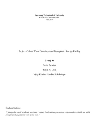
  • 2. MSE5183 Group W Project Fall 2014 2 of 34 ABSTRACT We designed and built a small robot with the purpose of identifying and retrieving a number of small round storage containers (tennis balls), and delivering them to a long term storage facility (by dropping them through a hole in the ground). To achieve this goal, we built a chassis capable of fitting within the storage shed (a 12” cube), selected sensors to identify the storage containers, the walls around the facility, and the path to the long term storage facility, and wrote code to navigate the robot through the process of picking up containers and conveying them to the storage facility, with the goal of moving up to three containers in less that one minute. INTRODUCTION The project involves the creation of an autonomous robot to operate inside a 7’x7’ surface, bounded by red lines and 7” high walls, identify waste storage containers (tennis balls), collect them, and move them to a long term storage facility (a hole in the surface of the board). The surface of the board is white, and there is a large black circular path around the center, leading to the storage facility borehole. During the demonstration, the position of the robot and up to three containment vessels will be randomly determined.   Figure  1:  Operational  surface  layout   We chose to use an Arduino Uno R3 processor as controller for the project, as it was the only platform that all members of the project group were familiar with.
  • 3. MSE5183 Group W Project Fall 2014 3 of 34 ROBOT DESIGN 1. Drivetrain and Chassis We originally hoped to find a moderately priced (under $100) chassis including motors and wheels to stand as a base from which to build the remainder of the project. We tested a number of motors of the types that are included with inexpensive chassis kits, and were not impressed with their capabilities. The few kits that did look to meet our needs far exceeded our price range. We determined that we’d likely be better off getting some higher quality motors and controllers, and building our own chassis around them. One of the group members had some motor/transmission/wheel combination modules in his basement, leftover from a previous project. He had originally considered them too large (6” wheels) for this project, but the group decided that the large diameter of the wheels could be considered a positive attribute, as they might allow the robot to ignore the hole in the board which might serve as a trap for smaller diameter wheels. The group concluded that they’d be a preferred alternative to ordering new motors and waiting for shipping. As an additional bonus, since the tall wheels have the motor/transmission connected at the top, they allow space in the bottom of the robot to collect the storage containers without having to pick them up off the surface. Unfortunately the wheel/transmission/motor assemblies were just slightly too wide (6.5”) to position them side by side within a 12” width. We explored various positions of the wheel assemblies, and eventually concluded that setting the wheels on alternate diagonal corners of the available space would provide the best performance for the least complexity. The group opted to use sliders at the opposite corners to prevent the structure tipping over and provide greater stability to the supporting portions of the robot (Arduino, motor controllers, batteries, and sensors), yet allow for movement in any direction. The easiest method to attach sliders to the base is with a long support column, which can be bolted to the base, nearly 7” up from the field surface. Rather than build a truss, or attach blocks to hold casters, we decided to use ladles, and bend the handles to bolt to the base. Ladles are already shaped properly for the least contact area with the surface, are (relatively) low friction stainless steel, are strong enough to support the weight of the robot, and yet light enough to avoid overloading the frame, and are less expensive than casters, furniture sliders, or other options that we considered. They also match with the unofficial theme of the group (Group W, from the Arlo Guthrie song “Alice’s Restaurant”). The group also had access to a number of Victor 883 Motor controllers, which have several advantages over the LM293 controllers we studied in class: 1) They are capable of controlling up to 24v at up to 60A of current. 2) They require only a single PWM input from the Arduino to control both speed and direction for each motor. 3) We didn’t have to wait for shipping, but had them immediately available.
  • 4. MSE5183 Group W Project Fall 2014 4 of 34 Figure  2:  Front  view  of  robot  showing  camera,  IR  sensors,  and  space  for  ball  collection  under  electronics.   We also identified two disadvantages: 1) They are more expensive than other motor controllers (mostly due to the enhanced current carrying capability). 2) They’re a little more complicated to control, since the speed and direction are both encoded into one signal (the same as a servo motor). We felt that the advantages outweighed the disadvantages, and decided to use these controllers rather than search for others with high enough current capability for the overly large motors we chose for the drivetrain.
  • 5. MSE5183 Group W Project Fall 2014 5 of 34 2. Gathering information for navigation (sensors) As the location of the storage containers was not originally described, we looked into the possibility of using a vision system to locate the containers. We were intrigued by the latest generation of the cmucam, the Pixy, and were impressed by the demonstration video, so we purchased one. The Pixy camera board consists of a video camera connected to a 200MHz dual-core ARM processor, running custom firmware to detect objects and report their locations through serial communications or an analog output. The fact that all of the image processing is done by the Pixy and only the location and size of the objects detected is reported to the Arduino processor was important to the decision to purchase one. We originally planned to use an ultrasound sensor to detect the distance to the balls, as the vision sensor doesn’t directly report a distance value. However, we soon discovered that due to their shape and composition, tennis balls are completely invisible to ultrasound sensors, so we decided to use a distance sensing infrared sensor instead. We also planned to use infrared sensors to detect the black line on the white surface so that we could follow the path to the hole. The original plan was to have two path following sensors, placed close enough together that the hole would be reported by both sensors sensing a lack of reflection. a. Vision Sensor (Pixy) Details The Pixy sensor provides information about objects detected by the camera with the following information, which is sent to the Arduino with SPI (Serial Peripheral Interface) protocol: Signature – The color signature of the detected object (up to 7 signatures can be set, so up to 7 different types of objects can be tracked). X – The location on the X axis of the center of the object. Y – The location on the Y axis of the center of the object. Width – the measurement (in pixels) of the width of the object. Height –measurement in pixels of the height of the object. Angle – for color codes, the angle at which the codes are aligned (not valid for normal objects).
  • 6. MSE5183 Group W Project Fall 2014 6 of 34 Figure  3:  Object  detection  overlaid  on  camera  picture.    Our  camera  is  mounted  upside  down,  but  this  picture  has  been  rotated  to   make  identification  easier.    The  captions  on  the  boxes  read  “S  =  1”  indicating  those  boxes  are  identified  as  signature  #1.    The  two   red  pixels  on  the  ball  in  the  background  indicate  that  it  is  starting  to  be  recognized,  but  has  not  yet  met  the  minimum  number  of   pixels  for  designation  as  an  object.   For this project, we’ll make use of the Signature, X, Y, Width, and Height components of the report. The Y (left/right) location will be the only one used for navigation. As a backup, we will also be able to verify the object with the IR sensor, so if the object appears to be large, but is not sensed by the IR sensor, it can safely be ignored as false. (This verification did not turn out to be necessary, so was not included in the final project). Technically, the camera could also be used to detect the red lines surrounding the playing field, especially as they have a nice bright primary color, but testing has shown that the width of the line is too small for the camera to reliably detect as an object, unless it is very close and pointing very nearly at the line. Some of the code for the Pixy demo which chases a ball is available online at: http://www.cmucam.org/boards/9/topics/2898?r=3372#message-3372 This is a good starting point for using Pixy to drive the robot toward an object (it’s incomplete as posted, because a lot of the code relies upon the physical characteristics of the robots drive system, and is only a starting point because as posted the code always tries to keep the robot at a set distance from the object, not driving over the object as we’ll require). In Figure 3, our robot would drive toward the ball on the right, as it’s object size (the white box drawn around the ball) is larger than the object size of the more distant ball.
  • 7. MSE5183 Group W Project Fall 2014 7 of 34 b. Ultrasound Sensors (HC-SR04) The HC-SR04 ultrasound sensor uses high frequency sound waves (much like a bat) to determine the distance to the nearest flat, hard surface. The distance is calculated by determining the time between the initial sound and the echo, then multiplying by the speed of sound and dividing by two (since the sound must travel out to the object, then be reflected back to the sensor). While the sensor has four pins, it is possible to operate using only three pins. In this configuration, the Trigger and Echo pins are tied together. Then the Arduino must output a pulse on the digital pin to trigger a sound, reconfigure the output as an input, and wait for the echo to be reported on the same line. The time between trigger and echo gives the distance to the object, as described above. While the ultrasound sensor is not capable of detecting the containment vessels, it is still a good measure of distance to the walls mounted around the playing field, and we intend to make use of several (3) of these to continually check the distance to the walls so that the navigation system can be aware of them and try to avoid them. c. Grove IR reflectance sensors IR reflectance sensors use an IR emitter and IR detector to determine whether an object is close. We are using them to determine the difference between a white (reflecting) object and a black (non-reflecting) object. These are digital sensors, so report only high (object detected) or low (object not detected). We are using two grove IR reflectance sensors to sense the black path leading to the long term storage facility. Initial testing shows that they should work, as long as they are mounted facing down and close (~ 2 cm) to the surface. Further testing shows that they’re not 100% accurate, and will occasionally miss the black line, or detect portions of it as not black, but with debouncing to eliminate detection of surface irregularities, they seem to be accurate enough to use for line detection. 3. Moving the storage containers As the group was initially ignorant of the initial disposition of the storage containers, we envisioned a number of methods to pick up and store the objects. However, we decided to spend most of our design time working on the chassis and known components, and to save speculation for later, when we’d know more about what was required and would be better able to develop a mechanism to move the containers. This turned out to be a good strategy, as the containers were not located on a platform from which they would need to be retrieved, but scattered randomly about the field. This meant that we could dispense with complex mechanisms to pick them up, and concentrate on methods to collect them and let the robot move them to the long term storage facility. In fact, since the long term storage facility is a hole in the playing field, that meant we didn’t need any mechanism to release the balls from their storage in the robot, we could simply drive over the hole and let them fall into it. Our chassis design was modified to include a tube running the length of the center of the robot, which would be long enough to temporarily hold 3 storage containers, which we were informed would be the maximum number of containers delivered at any one time. We felt that given the 1 minute time limit, it would be more advantageous to collect all the balls and deliver them at one time, instead of locating and delivering them one at a time. We had originally planned to use a servo motor to control a gate leading into the tube, but further experimentation has shown that it’s possible to build a passive gate that allows balls to enter, but prevents them leaving.
  • 8. MSE5183 Group W Project Fall 2014 8 of 34 Figure  4:  Gate  shown  without  and  with  a  ball.    The  ball  pushes  the  gate  open  from  the  outside,  but  the  upper  arm  of  the  gate   prevents  it  opening  in  the  other  direction.   NAVIGATION The robot navigation will differ depending on its mode. The mode will change several times during the course of its operation. It will need to seek for and collect objects (balls); seek for and follow the path to the hole, deliver the objects into the hole, and stop moving when finished. Different sensors will be used for different portions of the navigation. Searching for and collecting objects will involve the Pixy vision sensor to detect containers, with ultrasound sensors to avoid the walls, while path following will involve mainly the Grove IR sensors. Ultrasound sensors will be employed as collision prevention during the portions where the robot is not actively tracking a path or an object.
  • 9. MSE5183 Group W Project Fall 2014 9 of 34 Figure  5:  Finite  State  Machine  representation  
  • 10. MSE5183 Group W Project Fall 2014 10 of 34 A timer will be used to change navigational modes, since the motion period is limited to 60 seconds. 30 seconds will be allowed for container discovery and collection, and 30 seconds will be allowed for time to find and follow the path to the hole, and deliver the containers. When both times have expired, the robot will cease operation. DISCUSSION We encountered a number of problems while constructing and testing the robot. Here are descriptions of a few of the more memorable issues and how they were resolved. Vision Sensor issues When the Pixy arrived, we began to test it, and soon discovered that it is very dependent on lighting conditions, and on the color of the object to be tracked. It does operate very quickly, and can track a large number of objects at once, but we noticed a high number of false positives where the Pixy appears to see glare on shiny surfaces as similar to a lighter colored object, and falsely reports the glare as an object. We tried a variety of methods to identify and reject these false positives, looking at the relative stability of the image (false images tend to disappear at different angles), and the shape of the object reported (a ball should be close to square, oblong shapes can be rejected), but testing confirmed that the identification methods we chose we as likely to disallow a valid object as a false one. We also considered using a 2nd sensor to verify the existence of any object the camera reported. We originally wanted to use an ultrasound sensor to check the distance to the object, but discovered that the ultrasound sensors we tested were incapable of detecting a tennis ball, due to the shape (spherical, so very little sound is bounced back to the sensor) and surface (soft, so much of the sound is absorbed). Most other groups are using infrared sensors to detect balls, so we purchased a Sharp GP2Y0A60SZXF_E Analog infrared distance sensor from Polulu to act as backup to the vision system. Fortunately, when the actual surface became available for testing, we discovered that the false positives could be virtually eliminated by careful calibration of the brightness setting and the identification of the color (hue and balance) of the balls. Ultrasound Sensor issues We originally planned to use an ultrasound sensor to report the distance to the nearest storage container, even though the cone of detection is quite large at a distance of several feet, but testing showed that ultrasound sensors are not well suited to detect these types of storage containers. Their shape (spherical) causes the sound waves to bounce in almost every direction except back toward the sensor, and the soft, furry outer coating conspires to reduce the amplitude of any sound that is reflected back toward the sensor. The outcome is that the sensor is completely unable to sense the position of a storage container in its path, and in fact, the storage container can block the existence of other obstacles from the sensor. Our testing consisted of a hard, block shaped object located at a distance of 24” from the sensor, and a tennis ball randomly located at a variety of positions between the sensor and the block shaped object. We discovered that without the tennis ball, the distance to the block shaped object is reliably detected by the sensor. However, with the tennis ball in between the sensor and the block shaped object, the sensor might report 24”, or 25” or 60” or 200”. We assume the larger reported distances were due to the ball completely blocking or reflecting away the location pulse such that no echo was received by the sensor. We concluded that an Infrared sensor might be a better choice to detect a light colored object, and ordered a Sharp GP2Y0A60SZXF_E from Polulu for testing.
  • 11. MSE5183 Group W Project Fall 2014 11 of 34 Issues forming Acrylic We planned to make the ball corral (portion of the robot which holds collected containers) out of acrylic, as we had some on hand and one of our members had spent some time bending it on previous projects, and we thought it would be nice to be able to look through the side of the robot and see how many balls had been collected. We planned to heat it in an oven until it became flexible, then remove it and bend it over a form to take the shape of the form. We cut a 10” by 10” piece of clear acrylic, and heated it until it became ductile, but when we removed the sheet from the oven and draped it over a mold, it hardened nearly instantly. There was not enough time of workability to get more than ¼ of it shaped. We tried at least 4x before we gave up for the evening. Later, we repeated the exercise, but found a different molding form (a brick) that could put into the oven with the acrylic. We gave the brick about an hour to warm up before heating the acrylic, so the brick could be at oven temperature while we were molding the acrylic. With the oven door open to room temperature air, the acrylic still cooled to shape holding temperatures in seconds, but after three tries, we did get it molded well enough to use. It’s not pretty, but it does have the correct dimensions in the proper places. Issues discovered while testing We started by trying to test the vision system, but had some issues with the software. We decided to back up and start with the simpler software implementations first, so we tested the line following next. We originally had some issues with the IR sensors reporting imperfections in the surface as black lines, but after adding a debouncing routine, and adjusting the sensor calibration (a potentiometer is provided for this adjustment), we got the line following to work. At this time, it was taking about 15s for the robot to navigate 180 degrees of the circle and drop balls into the hole. We tested with one and two balls, and were generally successful dropping them both. We managed to resolve the issues with vision tracking by removing all other aspects of the code and testing only the object following code. Once that was working, we added back in the other sections and fixed or calibrated them to work as well. This formula got us a mostly working robot in only about two days worth of testing. With line following and vision tracking working, we quickly added some routines to navigate when there was not a line to follow or object to track. The plan for this portion of navigation is basically to go forward until close to the wall, then turn left. Since our turning is accomplished by driving the wheels in different directions for a set period of time, this effectively results in a random walk about the field. We put all the separate components together, tested to see that our timing algorithm was changing modes when it should, and started to collect balls. We had times where we could collect all three balls, but not make it to the hole before time ran out, and times where we could only collect one ball before starting to look for the path. We also had a number of occasions where we accidentally picked up a ball while navigating the path or accidentally knocked one into the hole. We discovered that the robot tended to run into the wall on occasions where it clearly should not have. Investigation showed that although we’d mounted our ultrasound sensors as low as possible on the top of the robot, and even had them sloping downward, they were placed just above the top of the wall, and could not reliably detect it when close until the robot bumped into them and changed angles. We moved the sensor facing directly forward to the underside of the top of the robot, but did not have space to move the other two.
  • 12. MSE5183 Group W Project Fall 2014 12 of 34 Over time, we found that if we increased the path following speed, it would result in only one ball dropping through the hole, even though we drove over it. We couldn’t slow the robot down without risking the ability to get to the hole, and we didn’t have a method of detecting the hole to tell us to slow down when the balls started dropping. Eventually, we figured out a way to add another ultrasound sensor to the rear of the robot, behind the ball collection corral. This sensor would detect the change in surface level as the hole went beneath it, and we could cause the robot to slowly back up and deposit the remaining balls into the hole. On the day before the final demonstration, we started to notice some problems with the IR sensors we were using to detect the line. Occasionally, the left side sensor would not detect a line as it was driven over. We attempted to adjust the sensor with it’s potentiometer, and found that the useful area of the potentiometer selection was approximately 1 degree. Any setting other than that 1 degree would always detect white, or always detect black. If time allowed we’d have replaced the sensor, but with less than 24 hours remaining, there was no chance to do so. We ended up using the sensor we had, and it performed acceptably for the demonstration, but we should have had spares from the beginning. CONCLUSIONS Although we were more worried about the dependability of the vision sensor, we actually had more problems with our other sensors. • We discovered that ultrasound sensors cannot see tennis balls. • We discovered that our wall detection sensors can only reliably detect the wall from a distance as they are mounted slightly higher than the top of the wall. • The initial placement of the downward facing infrared sensors on the sides of the ball collection corral put them far enough away from the hole that they could not be used to detect the hole, which led to us needing another ultrasound sensor placed at the rear of the robot, pointing down, to detect the hole. • One of our IR sensors developed problems the day before the demonstration, and we did not have a replacement available. We noticed that most other teams had problems with drivetrains (broken gears) and motor controllers. We used oversized motors and controllers, and drove them at low power and had no drivetrain reliability issues. We also believe that some other decisions helped to avoid major issues: • We kept construction simple, with fewer moving parts than most. • We kept our sensor and electronics power supply separate from the motor power supply. • We had overall fewer inputs and outputs (sensors and motors). We did successfully create a robot capable of finding three balls, picking them up, and dropping them into a hole in less than one minute, but the robot could still use improvements finding the path and avoiding the walls.
  • 13. MSE5183 Group W Project Fall 2014 13 of 34 APPENDIX A – ARDUINO UNO PINOUT
  • 14. MSE5183 Group W Project Fall 2014 14 of 34 APPENDIX B – REFERENCES Arduino References A nice library for timed events in Arduino (does not appear to be interrupt based) -- http://playground.arduino.cc/Code/SimpleTimer An interrupt based library for ultrasound sensors -- http://playground.arduino.cc/Code/NewPing Arduino Servo library to drive Victor 883 motor controllers -- http://arduino.cc/en/reference/servo Arduino Pixy library for Video sensor -- http://www.cmucam.org/attachments/download/1054/arduino_pixy- 0.1.3.zip Arduino Uno Simulator -- https://sites.google.com/site/unoardusim/home Pixy References Documentation: http://www.cmucam.org/projects/cmucam5/wiki/Wiki Code for Pixy kickstarter demo http://cmucam.org/boards/9/topics/2898?r=3427#message-3427 Similar use of Pixy in a robot http://www.bajdi.com/pixy-cmucam5/ Another similar use of Pixy in a robot https://learn.adafruit.com/downloads/pdf/pixy-pet-robot-color-vision-follower-using-pixycam.pdf Better description of previous project code https://learn.adafruit.com/pixy-pet-robot-color-vision-follower-using-pixycam/pixy-pet-code
  • 15. MSE5183 Group W Project Fall 2014 15 of 34 APPENDIX C – DATA SHEETS SeeedStudio Grove IR sensor – from http://www.seeedstudio.com/wiki/Grove_-_Infrared_Reflective_Sensor Specification • Voltage:4.5-5.5V • Current:14.69 - 15.35 mA • Effective Distance :4-15 mm • Detectable Length(black line) :1 mm • RPR220-Reflective photosensor: High resolution Infrared Reflective sensor. • LMV358: Rail-to-Rail Operational Amplifier. • Indicator LED: The LED will turn on when the received infrared light intensity exceeds a preset level. • Sensitivity adjusting potentiometer : adjust the light threshold of the sensor.
  • 16. MSE5183 Group W Project Fall 2014 16 of 34
  • 17. MSE5183 Group W Project Fall 2014 17 of 34
  • 18. MSE5183 Group W Project Fall 2014 18 of 34 APPENDIX E – SCHEMATIC
  • 19. MSE5183 Group W Project Fall 2014 19 of 34 APPENDIX F – SOURCE CODE /***************************************************************************/ /* MSE 5182 Final Project Fall 2014 */ /* Group W */ /* Project to detect tennis balls on a white surface, pick them up, */ /* and transport them to a hole in the surface. */ /* Robot uses two Victor 883 controllers to drive motors. */ /* A cmucam5 Pixy is used for video processing to detect balls. */ /* Two Grove IR sensors are used to detect a black line leading to the hole*/ /* Three ultrasound sensors detect the distance to the walls */ /* A fourth ultrasound sensor detects the hole */ /* */ /* This code is written to run on an Arduino Uno R3. */ /* */ /* Group W: */ /* David Bowden */ /* Salim Al Oufi */ /* Vijay Krishna Nandan Srikakolapu */ /***************************************************************************/ /* Version information */ /***************************************************************************/ /* V0.1 2014-12-03 Initial setup, first version reading Pixy data */ /* V0.2 2014-12-04 Serial print statements for debugging. */ /* V0.3 2014-12-04 Add ChooseTarget() to ignore transient Pixy objects. */ /* V0.4 2014-12-08 Add IR and ultrasound sensors, path following. */ /* V0.5 2014-12-08 Update ChooseTarget() to use ratio instead of stability.*/ /* V0.6 2014-12-10 Change Timer library for SimpleTimer library */ /* V0.7 2014-12-12 Put state machine parts together into a whole */ /* V0.8 2014-14-12 Add new state to back up when hole is detected */ /* V0.9 2014-14-12 Updates to hopefully speed up path detection */ /*V0.91 2014-15-12 Updates to path detection again, add new ultrasound */ /*V0.92 2014-15-12 Refactor state machine, rename ultrasound sensors */ /* V1.0 2014-17-12 Final version used in demonstration */ /***************************************************************************/ #include <Servo.h> /* Library for Victor 883 servo motor control */ #include <Pixy.h> /* Library for Pixy communications */ #include <SPI.h> /* Library for SPI communications (used by Pixy) */ #include <NewPing.h> /* Library for Ping ultrasound sensors */ #include <SimpleTimer.h> /* Library for time related events */ /***************************************************************************/ /* Motor and sensor definitions */ /***************************************************************************/ /* Hardware pin definitions for Arduino Uno */ #define PIXY_SPI_SCK 13 /* Serial communications pins for Pixy Camera */ #define PIXY_SPI_MISO 12 #define PIXY_SPI_MOSI 11 #define MOTOR_PIN_RIGHT 10 /* Output pin for right motor control */ #define MOTOR_PIN_LEFT 9 /* Output pin for left motor control */ #define SENSOR_PIN_LINE_RIGHT 8 /* Input pin for right side Grove IR line sensor */ #define SENSOR_PIN_LINE_LEFT 7 /* Input pin for left side Grove IR line sensor */ #define UNUSED_DIGITAL_PIN1 6 /* Unused I/O pin */ #define SENSOR_PIN_US_FRONT 5 /* I/O pin for front ultrasound distance sensor */ #define SENSOR_PIN_US_DOWN 4 /* I/O pin for down ultrasound distance sensor */ #define SENSOR_PIN_US_LEFT 3 /* I/O pin for left ultrasound distance sensor */ #define SENSOR_PIN_US_RIGHT 2 /* I/O pin for right ultrasound distance sensor */ #define USB_PIN1 1 /* Serial lines for programming/debugging */ #define USB_PIN2 0 #define SENSOR_PIN_ANALOG_IR A0 /* Analog input for Sharp IR distance sensor */ #define UNUSED_ANALOG_PIN1 A1 /* Currently unused */ #define UNUSED_ANALOG_PIN2 A2 #define UNUSED_ANALOG_PIN3 A3
  • 20. MSE5183 Group W Project Fall 2014 20 of 34 #define UNUSED_ANALOG_PIN4 A4 /* Possible I2C pin SDA for compass sensor */ #define UNUSED_ANALOG_PIN5 A5 /* Possible I2C pin SCL for compass sensor */ /* Motor speed settings */ #define MOTOR_FWD_SLOW 17 /* Motor speed values for non-vision control */ #define MOTOR_STOP 0 #define MOTOR_REV_SLOW -13 #define TURN_COUNT 40 /* Number of 20ms loops it takes to turn about 90 deg */ #define SERVO_STOP 90 /* Servo controls are measured in relation to 90 */ /* Note: MOTOR_MAX cannot exceed 90 and MOTOR_MIN cannot be less than -90 */ #define MOTOR_MAX 30 /* Maximum value allowed for motor speed control */ #define MOTOR_MIN -30 /* Minimum value allowed for motor speed control */ /* Note: SERVO_MAX cannot exceed 180 and SERVO_MIN cannot be less than 0 */ #define SERVO_MAX 105 /* Belt and suspenders to prevent too much power */ #define SERVO_MIN 80 /* Belt and suspenders to prevent too much power */ /* Motor axis settings */ #define LEFT_AXIS 0 /* Left and right axis definitions for motors */ #define RIGHT_AXIS 1 #define TRANS_AXIS 0 /* Rotation and translation axis definitions */ #define ROT_AXIS 1 /* These next two definitions determine the control points for the PD loop. Objects detected by the Pixy sensor will have their locations compared to these values, and the differences will drive the robot to move toward the object location. */ /* Note: a Y_TRACK location of 199 means that the robot should go forward towards a detected object until it is no longer visible. */ #define Y_TRACK 100 /* Desired Y (up/down) location of objects */ #define X_CENTER (320/2) /* Pixy ratio definitions: Ratio is multiplied by 1000 to get 3 significant figures */ /* A ratio of 1.0 (1000) is most desirable, as that's a square object. These values define the accepatable range for an object to track */ #define MIN_RATIO 100 /* 0.5 * 1000 */ #define MAX_RATIO 3000 /* 1.5 * 1000 */ /* Ultrasound sensor definitions */ #define SONAR_NUM 4 /* Number or sensors */ #define MAX_DISTANCE 200 /* Maximum distance (in cm) to ping */ #define PING_INTERVAL 33 /* Milliseconds between sensor pings */ /* (29ms is about the minimum interval to avoid cross-sensor echo). */ /* With four sensors reading at 33ms intervals, all sensors will update every 132 ms */ /* Define names for each sensor in the array, to make array accesses easier */ #define US_FRONT 0 /* Currently pointing front */ #define US_DOWN 1 /* Currently pointing down */ #define US_F_LEFT 2 /* Front/left */ #define US_F_RIGHT 3 /* Front/right sensor */ #define OBJECT_CLOSE 50 /* Front distance (cm) at which a turn is indicated */ #define TRUE 1 #define FALSE 0 #define LINE_LEFT 1 #define LINE_RIGHT 2 /***************************************************************************/ /* Global variable declarations */ /***************************************************************************/ /* Enumerated States for Finite State Machine */
  • 21. MSE5183 Group W Project Fall 2014 21 of 34 enum states_t { START, /* First and Last state */ SEARCH, /* Use Pixy sensor to find a ball */ FIND_LINE, /* Drive forward until the line sensors report */ TURN_TO_FOLLOW, /* Turn to align line sensors with the line */ TURN_TO_FOLLOW2, FOLLOW_LINE, /* Follow the line */ FOLLOW_LINE_LEFT, FOLLOW_LINE_RIGHT, REVERSE, /* Back up to drop balls */ FORWARD_SLOW, STOP } state = START; enum findBallState_t { BALL_GET_TARGET, BALL_CONTINUE_FWD, BALL_GO_STRAIGHT, BALL_TURN_LEFT, BALL_TURN_RIGHT } findBallState = BALL_GO_STRAIGHT; enum findLineState_t { LINE_GO_STRAIGHT, LINE_TURN_LEFT, LINE_TURN_RIGHT } findLineState = LINE_GO_STRAIGHT; /* Motor Controls */ Servo motorLeft; /* Create servo objects to control the drive wheels */ Servo motorRight; /* Pixy Camera */ Pixy pixy; /* Create pixy object to contain data from camera */ uint16_t blocks; int objNum; /* number of object voted for movement */ int objSelX; /* X coordinate of selected object */ int objErrX; /* Difference between selected x coordinate and screen center */ /* Infrared Line Sensor variables */ boolean lineSensorLeft; /* Value of the IR line tracking sensor on the left side */ boolean lineSensorRight; /* Value of the IR line tracking sensor on the right side */ /* Ultrasound distance sensor variables */ unsigned long pingTimer[SONAR_NUM]; /* Times the next ping for each sensor. */ unsigned int pingDistCm[SONAR_NUM]; /* Where the ping distances are stored. */ uint8_t currentSensor = 0; /* Keeps track of which sensor is active. */ /* Ultrasound Sensor object array. */ /* Contains each sensor's trigger pin, echo pin, and max distance to ping. */ /* Note that for this project, all trigger and echo pins are tied together */ NewPing sonar[SONAR_NUM] = { NewPing(SENSOR_PIN_US_FRONT, SENSOR_PIN_US_FRONT, MAX_DISTANCE), NewPing(SENSOR_PIN_US_DOWN, SENSOR_PIN_US_DOWN, MAX_DISTANCE), NewPing(SENSOR_PIN_US_LEFT, SENSOR_PIN_US_LEFT, MAX_DISTANCE), NewPing(SENSOR_PIN_US_RIGHT, SENSOR_PIN_US_RIGHT, MAX_DISTANCE) };
  • 22. MSE5183 Group W Project Fall 2014 22 of 34 /* Takes care of timed events */ SimpleTimer timer; /* Separates first loop from others */ boolean firstTime; boolean newBlocks; /* TRUE when new data has been received from Pixy camera */ int turnCount; /* Counts number of loops while turning */ /********************************************************************************/ /* Video tracking Motor control routines */ /* borrowed from http://www.cmucam.org/boards/9/topics/2898?r=3372#message-3372 */ /* Changes were made to the original code -- mainly, integer sizes were */ /* reduced where possible, to reduce calculation times. Also, saturation */ /* testing was moved to after axis remapping to avoid mapping issues. */ /********************************************************************************/ class MotorLoop { public: MotorLoop(uint16_t pgain, uint16_t dgain); int32_t update(int32_t error); private: int32_t m_prevError; uint16_t m_pgain; uint16_t m_dgain; }; MotorLoop::MotorLoop(uint16_t pgain, uint16_t dgain) { m_pgain = pgain; m_dgain = dgain; m_prevError = 0x80000000; /* to indicate that it's never been set */ } /* control loop update! */ int32_t MotorLoop::update(int32_t error) { int32_t vel; if (m_prevError!=0x80000000) { /* calculate proportional-derivative values based on error from desired */ vel = (error*m_pgain + (error - m_prevError)*m_dgain)/1000; /* Note: Original code from cmucam.org had the saturation clipping here, but simulations showed that clipping before axis remapping could have unintended consequences, so it was moved to after the remapping. D. Bowden 2014-12-03 */ } m_prevError = error; return vel; } /* Clip motor control values if PD values go into saturation */ int32_t clipMotorControls(int32_t driveValue) { if (driveValue > MOTOR_MAX) driveValue = MOTOR_MAX; else if (driveValue < MOTOR_MIN) driveValue = MOTOR_MIN;
  • 23. MSE5183 Group W Project Fall 2014 23 of 34 return driveValue; } /* ReMap axes! go from translational/rotational to left/right wheel space */ void axisMap(int32_t in[], int32_t out[]) { out[LEFT_AXIS] = (in[TRANS_AXIS] - in[ROT_AXIS])/2; out[LEFT_AXIS] = clipMotorControls(out[LEFT_AXIS]); out[RIGHT_AXIS] = (in[TRANS_AXIS] + in[ROT_AXIS])/2; out[RIGHT_AXIS] = clipMotorControls(out[RIGHT_AXIS]); } /*******************************************************************************/ /* NOTE: Victor 883 controllers are designed to mimic servo motors */ /* Using the Servo object to control them: 0 degrees = full reverse 90 degrees = stop 180 degrees = full forward Values between 0 and 90 degrees are reverse, slowing as they approach 90 Values between 90 and 180 are forward, speeding up as they approach 180 Note that the direction for increasing speed is negative for reverse motion. */ /*******************************************************************************/ /* Set Motor Voltage, with compensation for drivetrain nonconformities */ void setMotorVoltage(uint8_t motor, int8_t S_speed) { int16_t tempSpeed; if (S_speed < 0) { /* Reduce reverse values to make them approximately equal to forward values */ tempSpeed = (S_speed*3)/4; } else { tempSpeed = S_speed; } /* Add 90 to speed value to make it a servo value */ tempSpeed = tempSpeed + SERVO_STOP; /* Check for saturation again, belt and suspenders */ if (tempSpeed > SERVO_MAX) tempSpeed = SERVO_MAX; else if (tempSpeed < SERVO_MIN) tempSpeed = SERVO_MIN; /* Only send speed values to predefined motors */ if (motor == LEFT_AXIS) { motorLeft.write((uint8_t(tempSpeed))); //Serial.print("Motor Left = "); //Serial.print(tempSpeed); } else if (motor == RIGHT_AXIS) { /* Right side is slightly weaker than left side. Bump it up a little */ if (tempSpeed > SERVO_STOP) { motorRight.write((uint8_t(tempSpeed+3))); }
  • 24. MSE5183 Group W Project Fall 2014 24 of 34 else if (tempSpeed < SERVO_STOP) { motorRight.write((uint8_t(tempSpeed-3))); } else { motorRight.write(SERVO_STOP); } //Serial.print("Motor Right = "); //Serial.println(tempSpeed + 3); } } /***************************************************************************/ /* Motor variable declarations */ /***************************************************************************/ /* Note that these variables declarations contain the Kp and Kd constants. These constants were originally X(500,800) Y(700,900) but have been reduced since I moved the Y coordinates. I also turned off the Kd calculation for the moment. */ static MotorLoop g_transLoop(500, 0); static MotorLoop g_rotLoop(400, 0); /* Call this routine with the location (x,y) of the object to be followed */ /* It will calculate left and right wheel commands based on that location */ void combine(uint32_t x, uint32_t y) { int32_t xError, yError, axesIn[2], axesOut[2]; /* Pixy screen coordinates have their origin (0,0) at the top left of the screen, and values increase going down (Y) and to the right (X) to 199 and 319 respectively. Pixy currently uses a 320x200 pixel screen, and reports the center location of objects using the same coordinate system. */ /* Note: The Group W Pixy is mounted upside down, inverting the coordinates. */ /* To compensate, the calculation is inverted. e.g. error is calculated with (x - desired) instead of (desired - x) */ /* Calculate error between desired (center) and actual positions */ xError = x - X_CENTER; yError = y - Y_TRACK; /* Convert that error value into translation and rotation values */ /* Translation and Rotation are used here instead of left/right wheel speeds because they have a more immediate relationship to the coordinates used by the Pixy camera */ /* For rotation, positive values are to the left, negative to the right */ /* For translation, positive values are forward, negative values are reverse */ axesIn[TRANS_AXIS] = g_transLoop.update(yError); axesIn[ROT_AXIS] = g_rotLoop.update(xError); /* Remap from translation/rotation to left/right motor values */ axisMap(axesIn, axesOut); /* Command motors with the values above */ //Serial.print("Left = "); //Serial.print(axesOut[LEFT_AXIS]); //Serial.print("Right = "); //Serial.println(axesOut[RIGHT_AXIS]); setMotorVoltage(LEFT_AXIS, axesOut[LEFT_AXIS]); setMotorVoltage(RIGHT_AXIS, axesOut[RIGHT_AXIS]); }
  • 25. MSE5183 Group W Project Fall 2014 25 of 34 /* Go through reported Pixy objects and find the largest one which has the correct signature and fits the desired ratio (near square, since a ball fits a square better than an oblong). Since Pixy reports them in size order, largest first, the first one that fits the requirements will be largest. */ int ChooseTarget(void) { int i; /* loop counter */ int ratio; /* Calculated ratio of object */ objSelX = 0; /* Set nominal values for these variables until they're replaced */ objErrX = 160; /* If new blocks were received */ if (blocks > 0) { /* Check all new blocks for matching objects */ for (i = 0; i < blocks; i++) /* i counts new blocks */ { /* Ignore new blocks with the wrong signature! */ if (pixy.blocks[i].signature == 1) { /* Calculate ratio of object */ ratio = (pixy.blocks[i].width * 1000)/pixy.blocks[i].height; if ((ratio > MIN_RATIO) && (ratio < MAX_RATIO)) { /* Ratio is within acceptable bounds, follow this target */ objSelX = pixy.blocks[i].x; break; /* skip remaining objects */ } } } } else { /* No objects from which to choose */ objSelX = -1; /* No movement */ } return (objSelX); } /* Ultrasound sensor ISR */ void echoCheck() { // If ping received, set the sensor distance to array. if (sonar[currentSensor].check_timer()) pingDistCm[currentSensor] = sonar[currentSensor].ping_result / US_ROUNDTRIP_CM; } /* Called when all ultrasound sensors are done reading */ void oneSensorCycle() { // Sensor ping cycle complete, do something with the results. for (uint8_t i = 0; i < SONAR_NUM; i++) { //Serial.print(i); //Serial.print("="); //Serial.print(pingDistCm[i]); //Serial.print("cm "); } //Serial.println(); } /* Helper functions for 5ms task */ int checkForWalls(void) /* Returns closest non-zero reading, or MAX if all readings are zero */ { int frontDist;
  • 26. MSE5183 Group W Project Fall 2014 26 of 34 /* Make frontDist the smallest non-zero reading of the three forward facing ultrasound sensor distances */ frontDist = pingDistCm[US_FRONT]; if (frontDist > pingDistCm[US_F_LEFT]) { frontDist = pingDistCm[US_F_LEFT]; } if (frontDist > pingDistCm[US_F_RIGHT]) { frontDist = pingDistCm[US_F_RIGHT]; } return frontDist; } /* Time related tasks */ void task_5ms(void) { int xCoord; int yCoord; static int DownSensorCnt; static int ReverseCnt; static int FindDir; int frontDist; /* Local variable for ultrasound Distance */ Serial.print("State: "); Serial.println(state); /***********************************/ /* State Machine */ /***********************************/ switch (state) { case START: /* Start here. */ //Serial.print("Startn"); setMotorVoltage(LEFT_AXIS, MOTOR_STOP); /* Make sure motor is stopped */ setMotorVoltage(RIGHT_AXIS, MOTOR_STOP); /* Make sure motor is stopped */ state = SEARCH; //state = FIND_LINE; pingDistCm[US_FRONT] = MAX_DISTANCE; FindDir = 0; turnCount = 0; break; case SEARCH: static boolean turning; static boolean targeting; static int target_loop; Serial.print("Mode: Searchn"); /* ChooseTarget returns X coordinate (0-319) of chosen target */ if (newBlocks) /* Only run when new data has been received from Pixy */ { newBlocks = FALSE; /* Reset for next time */ xCoord = ChooseTarget(); /* Look through Pixy data for a target to track */ if (xCoord > 0) /* Object is being tracked */ { findBallState = BALL_GET_TARGET; //Serial.println("Target chosen"); } /* State machine within Search */ switch (findBallState)
  • 27. MSE5183 Group W Project Fall 2014 27 of 34 { case BALL_GET_TARGET: if (xCoord <= 0) /* Target has been lost */ { findBallState = BALL_CONTINUE_FWD; target_loop = 0; } else { /* combine takes desired xCoord and yCoord and sets motors to move in that direction. */ /* When yCoord = Y_TRACK, simply turn in place. */ yCoord = Y_TRACK; if(abs(xCoord - X_CENTER) < 20) /* If X is near the center */ yCoord = 170; /* then move forward to capture it */ //Serial.println("Seeking Target"); //Serial.print("Y = "); //Serial.print(yCoord); //Serial.print("; X = "); //Serial.println(xCoord); combine(xCoord, yCoord); } break; case BALL_CONTINUE_FWD: /* Keep moving to pick ball up after it moves off screen */ target_loop++; if (target_loop > 80) { target_loop = 0; findBallState = BALL_GO_STRAIGHT; } else { Serial.println("Continue Moving"); //Serial.println(target_loop,DEC); xCoord = X_CENTER; yCoord = 170; combine(xCoord,yCoord); } break; case BALL_GO_STRAIGHT: /* Check ultrasound sensors for closest wall distance */ frontDist = min(pingDistCm[US_FRONT], pingDistCm[US_F_LEFT]); Serial.println("Go Straight"); //Serial.println("Ultrasound Front = "); //Serial.println(frontDist,DEC); if (frontDist < OBJECT_CLOSE) { /* nearing wall, turn left */ findBallState = BALL_TURN_RIGHT; turnCount = 0; } else if (pingDistCm[US_F_RIGHT] < OBJECT_CLOSE) { /* nearing wall, turn right */ findBallState = BALL_TURN_LEFT; turnCount = 0; } else /* No walls nearby, go straight to look for target */ { //Serial.println("Go straight looking for target"); setMotorVoltage(RIGHT_AXIS, MOTOR_FWD_SLOW); setMotorVoltage(LEFT_AXIS, MOTOR_FWD_SLOW); }
  • 28. MSE5183 Group W Project Fall 2014 28 of 34 break; case BALL_TURN_LEFT: if (turnCount < TURN_COUNT) { turnCount++; Serial.println("Turn left to avoid wall"); setMotorVoltage(RIGHT_AXIS, MOTOR_FWD_SLOW); setMotorVoltage(LEFT_AXIS, MOTOR_REV_SLOW); } else { findBallState = BALL_GO_STRAIGHT; } break; case BALL_TURN_RIGHT: if (turnCount < TURN_COUNT) { turnCount++; Serial.println("Turn right to avoid wall"); setMotorVoltage(RIGHT_AXIS, MOTOR_REV_SLOW); setMotorVoltage(LEFT_AXIS, MOTOR_FWD_SLOW); } else { findBallState = BALL_GO_STRAIGHT; } break; }/* end findBallState switch */ }/* end if(newblocks) */ break; /* end Search case */ case FIND_LINE: Serial.print("Mode: Find Linen"); //Serial.print("Sensors: "); //Serial.print(lineSensorLeft); //Serial.println(lineSensorRight); ReverseCnt = 0; /* Allow reverse to work again if line is lost */ /* Grove sensors report high for no reflectance, so high = black */ if (lineSensorLeft && lineSensorRight) { /* If both sensors are high, the robot is at a right angle to the line. Turn about 90deg to follow the line */ state = TURN_TO_FOLLOW; } else if (lineSensorLeft) { /* Line has been seen */ FindDir = LINE_LEFT; } else if (lineSensorRight) { /* Line has been seen */ FindDir = LINE_RIGHT; } else { /* If neither sensor sees the black line now, check to see if one did. */ if (FindDir > 0) { /* Right or left sensor saw the line in the past, but does not see it now. We crossed a line, so assume we now straddle the line. */ Serial.print("Follow Line"); state = FOLLOW_LINE;
  • 29. MSE5183 Group W Project Fall 2014 29 of 34 DownSensorCnt = 0; turnCount = 0; FindDir = 0; } } switch (findLineState) { case LINE_GO_STRAIGHT: frontDist = pingDistCm[US_FRONT]; //Serial.print("Front Dist = "); //Serial.println(frontDist); /* Check for walls in the front */ /* If no wall is closer than 20" (50cm), move forward */ if (frontDist < 30) { /* A wall is approaching. Turn right */ turnCount = 0; findLineState = LINE_TURN_RIGHT; } else if (pingDistCm[US_F_RIGHT] < 30) { /* nearing wall, turn left */ findLineState = LINE_TURN_LEFT; turnCount = 0; } else { /* No Obstacles reported, OK to go straight */ //Serial.println("Go straight looking for line"); setMotorVoltage(RIGHT_AXIS, MOTOR_FWD_SLOW); setMotorVoltage(LEFT_AXIS, MOTOR_FWD_SLOW); } break; case LINE_TURN_LEFT: if (turnCount < 260) /* Turn about 135-180 degrees */ { turnCount++; //Serial.print("Turning Left. Turn Count ="); //Serial.println(turnCount,DEC); /* Rotate by moving wheels in opposite directions */ setMotorVoltage(RIGHT_AXIS, MOTOR_FWD_SLOW); setMotorVoltage(LEFT_AXIS, MOTOR_REV_SLOW); } else { findLineState = LINE_GO_STRAIGHT; } break; case LINE_TURN_RIGHT: if (turnCount < 260) /* Turn about 135-180 degrees */ { turnCount++; //Serial.print("Turning Right. Turn Count ="); //Serial.println(turnCount,DEC); /* Rotate by moving wheels in opposite directions */ setMotorVoltage(RIGHT_AXIS, MOTOR_REV_SLOW); setMotorVoltage(LEFT_AXIS, MOTOR_FWD_SLOW); } else { findLineState = LINE_GO_STRAIGHT; }
  • 30. MSE5183 Group W Project Fall 2014 30 of 34 break; } /* End findLineState switch */ break; /* This state should start with both sensors on (or near) the black line. */ case TURN_TO_FOLLOW: Serial.print("Turn to Follow Linen"); turnCount++; if (turnCount < 40) { /* Back up just a bit */ setMotorVoltage(RIGHT_AXIS, MOTOR_REV_SLOW); setMotorVoltage(LEFT_AXIS, MOTOR_REV_SLOW); } /* If a sensor sees the line, turn a little */ else if (lineSensorLeft || lineSensorRight) { state = TURN_TO_FOLLOW2; turnCount = 0; } else /* If neither sensor sees a line, turn until one does */ { static int count = 0; count++; if (count < 400) { /* Rotate left until one sensor sees black */ /* Rotate by moving wheels in opposite directions */ setMotorVoltage(RIGHT_AXIS, MOTOR_FWD_SLOW); setMotorVoltage(LEFT_AXIS, MOTOR_REV_SLOW); } else { /* If we rotate too far, go back to search for the line */ state = FIND_LINE; findLineState = LINE_GO_STRAIGHT; } } break; case TURN_TO_FOLLOW2: Serial.print("Turn to Follow2n"); turnCount++; /* Turn right */ if (turnCount < 210) { /* Rotate by moving wheels in opposite directions */ setMotorVoltage(RIGHT_AXIS, MOTOR_REV_SLOW); setMotorVoltage(LEFT_AXIS, MOTOR_FWD_SLOW); } else { /* Ignore all possible errors for now. Add in error checking later */ state = FOLLOW_LINE; DownSensorCnt = 0; turnCount = 0; } break; case FOLLOW_LINE: Serial.print("Follow linen"); frontDist = checkForWalls(); //Serial.print("Front Distance = "); //Serial.println(frontDist); if ((frontDist > 0) && (frontDist < 9)) /* Imminent collision -- change states */ { state = FIND_LINE; /* Let FIND_LINE determine which way to turn */
  • 31. MSE5183 Group W Project Fall 2014 31 of 34 findLineState = LINE_GO_STRAIGHT; } /* Check for the hole */ else if ((pingDistCm[US_DOWN] > 4) || (pingDistCm[US_DOWN] < 2)) { DownSensorCnt++; /* Debouncing hole sensor (5ms per loop!) */ /* (Debounce must be > 133ms as that's the max sensor read time) */ if (DownSensorCnt > 30) { state = REVERSE; turnCount = 0; } } else if (lineSensorLeft) { state = FOLLOW_LINE_LEFT; turnCount = 0; } else if (lineSensorRight) { state = FOLLOW_LINE_RIGHT; turnCount = 0; } else /* Go forward */ { setMotorVoltage(RIGHT_AXIS, MOTOR_FWD_SLOW); setMotorVoltage(LEFT_AXIS, MOTOR_FWD_SLOW); } break; case FOLLOW_LINE_LEFT: /* Check for the hole */ if ((pingDistCm[US_DOWN] > 3) || (pingDistCm[US_DOWN] < 2)) { DownSensorCnt++; /* Debouncing hole sensor (5ms per loop!) */ /* (Debounce must be > 133ms as that's the max sensor read time) */ if (DownSensorCnt > 30) { state = REVERSE; turnCount = 0; } } /* Turn toward the left sensor */ Serial.print("Follow turn leftn"); setMotorVoltage(RIGHT_AXIS, (MOTOR_FWD_SLOW * 3/4)); setMotorVoltage(LEFT_AXIS, (MOTOR_REV_SLOW * 3/4)); turnCount++; if (turnCount >= 55) { state = FOLLOW_LINE; DownSensorCnt = 0; } break; case FOLLOW_LINE_RIGHT: /* Check for the hole */ if ((pingDistCm[US_DOWN] > 3) || (pingDistCm[US_DOWN] < 2)) { DownSensorCnt++; /* Debouncing hole sensor (5ms per loop!) */ /* (Debounce must be > 133ms as that's the max sensor read time) */ if (DownSensorCnt > 28) {
  • 32. MSE5183 Group W Project Fall 2014 32 of 34 state = REVERSE; turnCount = 0; } } /* Turn toward the right sensor */ Serial.print("Follow Turn Rightn"); setMotorVoltage(LEFT_AXIS, (MOTOR_FWD_SLOW * 3/4)); setMotorVoltage(RIGHT_AXIS, (MOTOR_REV_SLOW * 3/4)); turnCount++; if (turnCount >= 55) { state = FOLLOW_LINE; DownSensorCnt = 0; } break; case REVERSE: /* Back up to try and drop balls */ //Serial.print("Reverse to drop ballsn"); if (ReverseCnt > 2) { state = FOLLOW_LINE; } else { setMotorVoltage(LEFT_AXIS, (MOTOR_REV_SLOW/2)); setMotorVoltage(RIGHT_AXIS, (MOTOR_REV_SLOW/2)); turnCount++; if (turnCount >= 200) { state = FORWARD_SLOW; turnCount = 0; ReverseCnt++; } } break; case FORWARD_SLOW: /* Back up to try and drop balls */ //Serial.print("Forward slow to drop ballsn"); setMotorVoltage(LEFT_AXIS, (MOTOR_FWD_SLOW/2)); setMotorVoltage(RIGHT_AXIS, (MOTOR_FWD_SLOW/2)); turnCount++; if (turnCount >= 200) { state = REVERSE; turnCount = 0; } break; case STOP: /* Come here at 61 sec or on unrecoverable error */ //Serial.print("Stopn"); setMotorVoltage(LEFT_AXIS, MOTOR_STOP); /* Make sure motor is stopped */ setMotorVoltage(RIGHT_AXIS, MOTOR_STOP); /* Make sure motor is stopped */ } /* end state machine */ } void getObjects(void) { /* 20 millisecond task to collect data from Pixy */ //Serial.println("GetObjects"); blocks = pixy.getBlocks(); newBlocks = TRUE; }
  • 33. MSE5183 Group W Project Fall 2014 33 of 34 void findPath(void) { /* 30 seconds have elapsed. Stop seeking containment vessels, and start searching for borehole. */ //Serial.println("FindPath"); state = FIND_LINE; turnCount = 0; } void done(void) { /* 61 seconds have elapsed. Stop all motion. The task is ended. */ Serial.println("Done"); state = STOP; } /***************************************************************************/ /* Main control routines */ /***************************************************************************/ void setup() { motorLeft.attach(MOTOR_PIN_LEFT); /* Attach the left drive motor to servo */ motorLeft.write(SERVO_STOP); /* Make sure motor is stopped */ motorRight.attach(MOTOR_PIN_RIGHT);/* Attachs the right drive motor to servo */ motorRight.write(SERVO_STOP); /* Make sure motor is stopped */ Serial.begin(115200); /* Faster speed means less delay when debugging */ Serial.print("Starting...n"); pixy.init(); /* Start SPI communication with Pixy */ /* Set up I/O for sensors */ pinMode(SENSOR_PIN_LINE_RIGHT,INPUT); pinMode(SENSOR_PIN_LINE_LEFT,INPUT); /* Start rotation of Ultrasound sensor readings */ pingTimer[0] = millis() + 75; /* First ping starts at 75ms */ for (uint8_t i = 1; i < SONAR_NUM; i++) /* Set the starting time for each sensor. */ { pingTimer[i] = pingTimer[i - 1] + PING_INTERVAL; pingDistCm[i] = MAX_DISTANCE; } /* Set up timer related functions */ /* Call 5ms task every 5ms */ timer.setInterval(5, task_5ms); /* Call getObjects task every 20ms */ timer.setInterval(20, getObjects); /* After 30 seconds (30,000 ms) have elapsed, search for path to borehole */ timer.setTimeout(30000L, findPath); /* After 61 seconds (61,000 ms) have elapsed, stop */ timer.setTimeout(61000L, done); firstTime = TRUE; newBlocks = FALSE; } /*************************************************/ void loop() { static int i = 0; int tempSensorLeft; int tempSensorRight; static int oldTempSensorLeft;
  • 34. MSE5183 Group W Project Fall 2014 34 of 34 static int oldTempSensorRight; /***********************************/ /* Sensor updates */ /***********************************/ /* Read IR line following sensor states */ tempSensorRight = digitalRead(SENSOR_PIN_LINE_RIGHT); tempSensorLeft = digitalRead(SENSOR_PIN_LINE_LEFT); /* Debounce IR sensors */ if (lineSensorRight != tempSensorRight) if (oldTempSensorRight == tempSensorRight) lineSensorRight = tempSensorRight; else oldTempSensorRight = tempSensorRight; if (lineSensorLeft != tempSensorLeft) if (oldTempSensorLeft == tempSensorLeft) lineSensorLeft = tempSensorLeft; else oldTempSensorLeft = tempSensorLeft; /* Read ultrasound sensor distances */ /* This code comes from an example in the NewPing Library */ for (uint8_t i = 0; i < SONAR_NUM; i++) /* Loop through all the sensors */ { // Is it this sensor's time to ping? if (millis() >= pingTimer[i]) { // Set next time this sensor will be pinged.state pingTimer[i] += PING_INTERVAL * SONAR_NUM; // Sensor ping cycle complete, do something with the results. if (i == 0 && currentSensor == SONAR_NUM - 1) oneSensorCycle(); { // Make sure previous timer is canceled before starting a new ping. sonar[currentSensor].timer_stop(); /* If distance is zero, no ping was returned, so make it max */ if (pingDistCm[currentSensor] == 0) pingDistCm[currentSensor] = MAX_DISTANCE; } currentSensor = i; // Sensor being accessed. // Make distance zero in case there's no ping echo for this sensor. pingDistCm[currentSensor] = MAX_DISTANCE; // Do the ping (processing continues, interrupt will call echoCheck). sonar[currentSensor].ping_timer(echoCheck); } } timer.run(); /* Update timed events */ } /* end loop */