SlideShare a Scribd company logo
1 of 6
Download to read offline
Materials 2: Properties of Materials
Materials Selection Group Assignment
Light Aircraft Landing Gear Strut
Group 6
19 December 2014
1 Introduction
Aircraft landing gears can be split into 2 parts: the solid cylindrical strut to support the
plane on the ground and withstand the forces during landing, and the damping element
to reduce those forces. This analysis seeks to determine the most suitable material the
landing gear strut of a light aircraft. A light aircraft is classified as an aircraft that has a
maximum gross takeoff weight of 5670 Kg or less. Consequently, the aircraft selected was
the Cessna TTX, a 4 passenger high performance aircraft with a maximum gross takeoff
weight of 1633 Kg.
Figure 1: Cessna TTX
Figure 1 shows the Cessna TTX with its landing gear highlighted in red. It uses a
tricycle type configuration with one gear at the front of the plane and 2 gears further back
near the wings of the plane. The landing gear of the Cessna TTX is non-retractable, which
means that it will be exposed to the elements during operation. However, the following
analysis will only consider compressive axial loading of the strut and environmental factors
such as corrosion, as other forces resulting from particulate impacts and air resistance
will be assumed to be negligible. The requirements will first be translated into a table
of constraints and objectives and then material indices will be derived for screening and
ranking. As there are multiple objectives the final ranking will be done with a penalty
function.
1
Materials selection group 6
2 Translation
Function Support the weight of a Cessna TTX aircraft during landing and
while the plane is on the ground
Constraints Specified length, L
Minimum compressive strength
Resist corrosion in water
Resist buckling during landing
Minimum fatigue endurance strength
Moderately easy to manufacture
Objectives Minimise weight
Minimise material cost
Free Variable Choice of material
Cross-sectional area, A
Table 1: Translation
Many constraints and objectives were considered for our translation table. For ex-
ample, the minimum service temperature of the material was considered but was not
implemented because it proved unnecessary seeing as the constraint did not remove any
materials. Hardness was also considered but was also rejected because any collision with
airborne particles will be unlikely to cause localised damage that will harm the integrity
of the structure.
The primary objective of this design is to minimise weight as it affects the fuel con-
sumption of the aircraft which leads to higher long-term running costs. The balance is
that the savings due to a cheaper material might outweight the future fuel savings.
3 Screening
3.1 Compressive Strength & Corrosion
After some research it was found that alloy steels and aluminium are the most common
materials for this type of strut. Therefore, in order to immediately screen out materials
that would be unsuitable for use on landing gear, a minimum compressive strength of
180MPa was applied, the lower limit stainless steels strength. This removed the weaker
materials in the Edupack library such as bamboo and removed all foams and elastomers.
Materials that were rated Limited Use or Unacceptable in fresh water we also screened
out, since the Cessna TTX would most likely experience a damp environment during its
life use, however, this only removed a very small number of materials.
3.2 Machinability
In stage 4 of the selection process another screening was applied to remove anything
with a rating for Formability, the ability of a material to be shaped or experience plastic
deformation without being damaged, lower than 3 in order to cut down the remaining
materials and so that the chosen material would be moderately easy to shape into the
required form. Again, this only removed a small number of materials. The result of
screening is shown below in Figure 2.
2
Materials selection group 6
Figure 2: Screening based on minimum compressive strength
4 Ranking
4.1 Buckling
By using the equations for the mass of a column, the minimum buckling load of a column
and the fatigue equation, two material indices can be calculated by eliminating the free
variable of the cross-sectional area. To find an index that will minimise the mass of the
strut while maximising its minimum bucking load, it is necessary to find an expression
for the cross-sectional area as a function of the mass, and rearrange the column buckling
equation to find another expression for the area.
The mass of a column is defined as:
m = ρAL, (1)
and therefore:
A =
m
ρL
(2)
Meanwhile, the expression for the minimum buckling load of a column, according to
the Euler Column Buckling formula, is
F =
π2
EI
L2
, (3)
where I is the area moment of inertia which, for a solid cylinder is defined as:
I =
πr4
4
=
A2
4π
(4)
Therefore,
F =
πEA2
4L2
(5)
3
Materials selection group 6
A =
4FL2
πE
(6)
m =
ρ
√
E
2L
F
π
(7)
Therefore, the required material index is:
M1 =
ρ
√
E
, (8)
4.2 Fatigue Strength
In order to calculate the material index to minimise the mass of the strut while maximising
the endurance toughness, it was necessary to first rearrange the fatigue equation to find
an expression for the cross-sectional area as a function of the fatigue endurance, and then
equate it with the expression for area as a function of mass.
σe =
F
A
(9)
A =
A
σe
(10)
m =
ρ
σe
F
L
(11)
This produces the material index:
M2 =
ρ
σe
, (12)
Then, the two indices are plotted together on the bubble plot in Figure 3, with M2
on the X-axis and M1 on the Y-axis. In order to minimise the mass while maximising
the buckling resistance and fatigue endurance, materials in the lower left of the chart
must be selected, as lower values of M1 and M2 indicate a high endurance and buckling
resistance relative to the density of the material. The selection curve was moved into
a position where stainless steel is on the outer edge, meaning that only other equal or
superior materials are left for selection.
4.3 Cost
More materials were removed by forming a second bubble plot that shows the material
cost per kilogram in relation to buckling strength and fatigue endurance. The material
indices for cost were the same as for mass but with ρ replaced by ρCM . The lower left
corner of the bubble plot is shown in Figure 4. The pink and yellow bubbles represent
several varieties of glass and ceramics respectively, both of which were screened out in
stage 4 by removing materials with poor manufacturability. A selection line was drawn
and moved to screen out several less desirable materials: such as Zirconia, which requires
a long and costly machining process to achieve the desired shape; Titanium alloys, which
are too brittle and expensive; and CFRP, which has low performance in moist and high
fatigue environments.
4
Materials selection group 6
Figure 3: Ranking based on specific fatgiue endurance and specific buckling strength
Figure 4: Ranking based on cost, fatigue endurance and buckling strength
The final step was to minimise the cost and weight of the material. Figure 5 shows
dotted lines to indicate potential penalty function lines where α = 300. The clear winning
material was cast magnesium alloy, since it is one of the lightest and cheapest materials,
and is easier to manufacture compared to wrought magnesium alloy.
5 Discussion
Magnesium alloys are already used in the aerospace industry, but in limited amounts.
They account for 1.0-1.5% of the average aircraft’s weight, whereas the most common
materials used for landing gear are strong and ductile specialist steels [1] and aluminium
alloys [2]. In fact, materials for aerospace are usually selected for having a high strength-
to-weight ratio and a high specific stiffness [3]. These are properties which were ranked
for in this project, meaning that the method by which the magnesium alloy was selected is
similar to that by which steels were chosen in industry. It is possible that errors were made
in this selection process. For example, it is important to note that the sources used in this
5
Materials selection group 6
Figure 5: Ranking based on cost and density
analysis of the elected material predate the development of many composite materials, and
there is a strong trend in the aerospace industry towards the use of composite materials.
It is also significant that Edupack measures the fatigue endurance as the fatigue stress
for a fatigue life of 107
cycles, whereas many forged aluminium landing gears demonstrate
lifespans of less than 6000 cycles, although these tests were carried out on much larger
commercial aircraft [2]. However, magnesium alloys are becoming increasingly prevalent
in aerospace applications and their limited use is more likely a result of implementational
inertia. Their many advantages include that they are cheaper than steel and lighter than
both steel and aluminium [4]. It is also easier to produce than aluminium alloys; which
must be heat treated, quenched and then aged by heat. The process by which aluminium
alloys are produced often distorts the metal, requiring correction by rolling [4].
6 Conclusion
In conclusion, the material best suited for use in a light aircraft landing strut is a cast
magnesium alloy, due to its superior mechanical properties, low weight and cost. Although
it is a newer material that is relatively untested for such an application, the data recording
its advantages is clear and it will likely form a much larger percentage of the weight of
aircraft in the future.
References
[1] Alexandru Nica Mechanics of Aerospace Materials. Elsevier Scientific Publishing Com-
pany, 1st edition, 1981.
[2] Alfred M Freudenthal Fatigue in Aircraft Structures. Academic Press Inc, 1st edition,
1956.
[3] Darrol Stinton The Anatomy of the Aeroplane. Blackwell Science Ltd, 2nd edition,
1998.
[4] CES Edupack datahseets. CES, 2014.
6

More Related Content

What's hot

Ultra-high performance concrete
Ultra-high performance concreteUltra-high performance concrete
Ultra-high performance concretehammad shah
 
Introduction to composite_materials in aerospace_applications
Introduction to composite_materials in aerospace_applicationsIntroduction to composite_materials in aerospace_applications
Introduction to composite_materials in aerospace_applicationsR.K. JAIN
 
Strength of materials_I
Strength of materials_IStrength of materials_I
Strength of materials_IPralhad Kore
 
Composite materials in aerospace applications
Composite materials in aerospace applicationsComposite materials in aerospace applications
Composite materials in aerospace applicationsUfuk KORTAĞ
 
ASTM E 09(COMPRESSION TEST)
ASTM E 09(COMPRESSION TEST)ASTM E 09(COMPRESSION TEST)
ASTM E 09(COMPRESSION TEST)Manthan Chavda
 
Application of composite materials in aerospace industry
Application of composite materials in aerospace industryApplication of composite materials in aerospace industry
Application of composite materials in aerospace industryAmol Chakankar
 
Cooling thrust chamber
Cooling thrust chamberCooling thrust chamber
Cooling thrust chamberVISHAL KAATAL
 
DEFLECTION OF BEAM
DEFLECTION OF BEAMDEFLECTION OF BEAM
DEFLECTION OF BEAMMEHALAS3
 
Compression test verification_for_a_wood
Compression test verification_for_a_woodCompression test verification_for_a_wood
Compression test verification_for_a_woodSumitThakur755213
 
Lec 2 stress strain diagram (lec 2)
Lec 2 stress strain diagram (lec 2)Lec 2 stress strain diagram (lec 2)
Lec 2 stress strain diagram (lec 2)Abdul Rehman Memon
 
Design of columns uniaxial load as per IS 456-2000
Design of columns  uniaxial load as per IS 456-2000Design of columns  uniaxial load as per IS 456-2000
Design of columns uniaxial load as per IS 456-2000PraveenKumar Shanmugam
 
SOM-BASIC CONCEPTS
SOM-BASIC CONCEPTSSOM-BASIC CONCEPTS
SOM-BASIC CONCEPTSDevraj152002
 
Wind load calculation
Wind load calculationWind load calculation
Wind load calculationGodfrey James
 
Shearing stress distribution_in_typical_cross
Shearing stress distribution_in_typical_crossShearing stress distribution_in_typical_cross
Shearing stress distribution_in_typical_crossMD RUKHASAR ALAM
 
Bending and Torsion A.Vinoth Jebaraj
Bending and Torsion A.Vinoth JebarajBending and Torsion A.Vinoth Jebaraj
Bending and Torsion A.Vinoth JebarajVinoth Jebaraj A
 

What's hot (20)

Ultra-high performance concrete
Ultra-high performance concreteUltra-high performance concrete
Ultra-high performance concrete
 
Introduction to composite_materials in aerospace_applications
Introduction to composite_materials in aerospace_applicationsIntroduction to composite_materials in aerospace_applications
Introduction to composite_materials in aerospace_applications
 
Application of composite materials in aerospace industry (1)
Application of composite materials in aerospace industry (1)Application of composite materials in aerospace industry (1)
Application of composite materials in aerospace industry (1)
 
Strength of materials_I
Strength of materials_IStrength of materials_I
Strength of materials_I
 
Kompozit zırh malzemeleri
Kompozit zırh malzemeleriKompozit zırh malzemeleri
Kompozit zırh malzemeleri
 
Composite materials in aerospace applications
Composite materials in aerospace applicationsComposite materials in aerospace applications
Composite materials in aerospace applications
 
Truss
TrussTruss
Truss
 
ASTM E 09(COMPRESSION TEST)
ASTM E 09(COMPRESSION TEST)ASTM E 09(COMPRESSION TEST)
ASTM E 09(COMPRESSION TEST)
 
Application of composite materials in aerospace industry
Application of composite materials in aerospace industryApplication of composite materials in aerospace industry
Application of composite materials in aerospace industry
 
Cooling thrust chamber
Cooling thrust chamberCooling thrust chamber
Cooling thrust chamber
 
DEFLECTION OF BEAM
DEFLECTION OF BEAMDEFLECTION OF BEAM
DEFLECTION OF BEAM
 
Compression test verification_for_a_wood
Compression test verification_for_a_woodCompression test verification_for_a_wood
Compression test verification_for_a_wood
 
Lec 2 stress strain diagram (lec 2)
Lec 2 stress strain diagram (lec 2)Lec 2 stress strain diagram (lec 2)
Lec 2 stress strain diagram (lec 2)
 
Design of columns uniaxial load as per IS 456-2000
Design of columns  uniaxial load as per IS 456-2000Design of columns  uniaxial load as per IS 456-2000
Design of columns uniaxial load as per IS 456-2000
 
SOM-BASIC CONCEPTS
SOM-BASIC CONCEPTSSOM-BASIC CONCEPTS
SOM-BASIC CONCEPTS
 
Wind load calculation
Wind load calculationWind load calculation
Wind load calculation
 
Unit 2 stresses in composite sections
Unit 2  stresses in composite sectionsUnit 2  stresses in composite sections
Unit 2 stresses in composite sections
 
Shearing stress distribution_in_typical_cross
Shearing stress distribution_in_typical_crossShearing stress distribution_in_typical_cross
Shearing stress distribution_in_typical_cross
 
Design of steel beams
Design of steel beamsDesign of steel beams
Design of steel beams
 
Bending and Torsion A.Vinoth Jebaraj
Bending and Torsion A.Vinoth JebarajBending and Torsion A.Vinoth Jebaraj
Bending and Torsion A.Vinoth Jebaraj
 

Similar to Light Aircraft Landing Gear Strut Group 6 Report

Carbon Fiber Fuselage Research Report
Carbon Fiber Fuselage Research ReportCarbon Fiber Fuselage Research Report
Carbon Fiber Fuselage Research ReportKristopherKerames
 
Design, Analysis and Testing of Wing Spar for Optimum Weight
Design, Analysis and Testing of Wing Spar for Optimum WeightDesign, Analysis and Testing of Wing Spar for Optimum Weight
Design, Analysis and Testing of Wing Spar for Optimum WeightRSIS International
 
IRJET- Particle Swarm Intelligence based Dynamics Economic Dispatch with Dail...
IRJET- Particle Swarm Intelligence based Dynamics Economic Dispatch with Dail...IRJET- Particle Swarm Intelligence based Dynamics Economic Dispatch with Dail...
IRJET- Particle Swarm Intelligence based Dynamics Economic Dispatch with Dail...IRJET Journal
 
A review of Carbon Nanotube Reinforced Aluminium Composite and Functionally ...
A review of Carbon Nanotube Reinforced Aluminium Composite  and Functionally ...A review of Carbon Nanotube Reinforced Aluminium Composite  and Functionally ...
A review of Carbon Nanotube Reinforced Aluminium Composite and Functionally ...IJMER
 
FEA Analyses of Kayak Paddles
FEA Analyses of Kayak PaddlesFEA Analyses of Kayak Paddles
FEA Analyses of Kayak PaddlesCampbell Simpson
 
Analysis of Stiffeners in a Semi Monocoque System of an Air Craft
Analysis of Stiffeners in a Semi Monocoque System of an Air CraftAnalysis of Stiffeners in a Semi Monocoque System of an Air Craft
Analysis of Stiffeners in a Semi Monocoque System of an Air Craftinventionjournals
 
AOE 3024 Wing Spar Design Project
AOE 3024 Wing Spar Design ProjectAOE 3024 Wing Spar Design Project
AOE 3024 Wing Spar Design ProjectMatt Kaiser
 
Studies on Strength Evaluation of Fiber Reinforced Plastic Composites
Studies on Strength Evaluation of Fiber Reinforced Plastic CompositesStudies on Strength Evaluation of Fiber Reinforced Plastic Composites
Studies on Strength Evaluation of Fiber Reinforced Plastic CompositesIJERA Editor
 
Mini Project - STRUCTURAL-ANALYSIS-AND-MATERIAL-SELECTION
Mini Project - STRUCTURAL-ANALYSIS-AND-MATERIAL-SELECTIONMini Project - STRUCTURAL-ANALYSIS-AND-MATERIAL-SELECTION
Mini Project - STRUCTURAL-ANALYSIS-AND-MATERIAL-SELECTIONdna1992
 
Investigation on Flexural Behaviour of Cold Formed Latticed Built-Up Beam
Investigation on Flexural Behaviour of Cold Formed Latticed Built-Up BeamInvestigation on Flexural Behaviour of Cold Formed Latticed Built-Up Beam
Investigation on Flexural Behaviour of Cold Formed Latticed Built-Up BeamDr. Amarjeet Singh
 
Model Optimization and structural Analysis of a Car Rim
Model Optimization and structural Analysis of a Car RimModel Optimization and structural Analysis of a Car Rim
Model Optimization and structural Analysis of a Car RimSai Narayana
 
Composite Materials in Aerospace Industry
Composite Materials in Aerospace IndustryComposite Materials in Aerospace Industry
Composite Materials in Aerospace IndustryNagababu Tallam
 
Iisrt akshata ht
Iisrt akshata htIisrt akshata ht
Iisrt akshata htIISRT
 
Aircraft Performance and Design Project
Aircraft Performance and Design ProjectAircraft Performance and Design Project
Aircraft Performance and Design ProjectElliot Farquhar
 
Finite Element Analysis of Roll Cage
Finite Element Analysis of Roll CageFinite Element Analysis of Roll Cage
Finite Element Analysis of Roll CageIJRESJOURNAL
 
IRJET- Design and Analysis of Opto Wing of an Aircraft using Ansys Workbench
IRJET- Design and Analysis of Opto Wing of an Aircraft using Ansys WorkbenchIRJET- Design and Analysis of Opto Wing of an Aircraft using Ansys Workbench
IRJET- Design and Analysis of Opto Wing of an Aircraft using Ansys WorkbenchIRJET Journal
 
Aircraft structure
Aircraft structureAircraft structure
Aircraft structuredarshakb
 

Similar to Light Aircraft Landing Gear Strut Group 6 Report (20)

Carbon Fiber Fuselage Research Report
Carbon Fiber Fuselage Research ReportCarbon Fiber Fuselage Research Report
Carbon Fiber Fuselage Research Report
 
Ac044199202
Ac044199202Ac044199202
Ac044199202
 
Application of Composite Material in Aerospace Industry
Application of Composite Material in Aerospace IndustryApplication of Composite Material in Aerospace Industry
Application of Composite Material in Aerospace Industry
 
Design, Analysis and Testing of Wing Spar for Optimum Weight
Design, Analysis and Testing of Wing Spar for Optimum WeightDesign, Analysis and Testing of Wing Spar for Optimum Weight
Design, Analysis and Testing of Wing Spar for Optimum Weight
 
IRJET- Particle Swarm Intelligence based Dynamics Economic Dispatch with Dail...
IRJET- Particle Swarm Intelligence based Dynamics Economic Dispatch with Dail...IRJET- Particle Swarm Intelligence based Dynamics Economic Dispatch with Dail...
IRJET- Particle Swarm Intelligence based Dynamics Economic Dispatch with Dail...
 
Ijett v67 i12p205
Ijett v67 i12p205Ijett v67 i12p205
Ijett v67 i12p205
 
A review of Carbon Nanotube Reinforced Aluminium Composite and Functionally ...
A review of Carbon Nanotube Reinforced Aluminium Composite  and Functionally ...A review of Carbon Nanotube Reinforced Aluminium Composite  and Functionally ...
A review of Carbon Nanotube Reinforced Aluminium Composite and Functionally ...
 
FEA Analyses of Kayak Paddles
FEA Analyses of Kayak PaddlesFEA Analyses of Kayak Paddles
FEA Analyses of Kayak Paddles
 
Analysis of Stiffeners in a Semi Monocoque System of an Air Craft
Analysis of Stiffeners in a Semi Monocoque System of an Air CraftAnalysis of Stiffeners in a Semi Monocoque System of an Air Craft
Analysis of Stiffeners in a Semi Monocoque System of an Air Craft
 
AOE 3024 Wing Spar Design Project
AOE 3024 Wing Spar Design ProjectAOE 3024 Wing Spar Design Project
AOE 3024 Wing Spar Design Project
 
Studies on Strength Evaluation of Fiber Reinforced Plastic Composites
Studies on Strength Evaluation of Fiber Reinforced Plastic CompositesStudies on Strength Evaluation of Fiber Reinforced Plastic Composites
Studies on Strength Evaluation of Fiber Reinforced Plastic Composites
 
Mini Project - STRUCTURAL-ANALYSIS-AND-MATERIAL-SELECTION
Mini Project - STRUCTURAL-ANALYSIS-AND-MATERIAL-SELECTIONMini Project - STRUCTURAL-ANALYSIS-AND-MATERIAL-SELECTION
Mini Project - STRUCTURAL-ANALYSIS-AND-MATERIAL-SELECTION
 
Investigation on Flexural Behaviour of Cold Formed Latticed Built-Up Beam
Investigation on Flexural Behaviour of Cold Formed Latticed Built-Up BeamInvestigation on Flexural Behaviour of Cold Formed Latticed Built-Up Beam
Investigation on Flexural Behaviour of Cold Formed Latticed Built-Up Beam
 
Model Optimization and structural Analysis of a Car Rim
Model Optimization and structural Analysis of a Car RimModel Optimization and structural Analysis of a Car Rim
Model Optimization and structural Analysis of a Car Rim
 
Composite Materials in Aerospace Industry
Composite Materials in Aerospace IndustryComposite Materials in Aerospace Industry
Composite Materials in Aerospace Industry
 
Iisrt akshata ht
Iisrt akshata htIisrt akshata ht
Iisrt akshata ht
 
Aircraft Performance and Design Project
Aircraft Performance and Design ProjectAircraft Performance and Design Project
Aircraft Performance and Design Project
 
Finite Element Analysis of Roll Cage
Finite Element Analysis of Roll CageFinite Element Analysis of Roll Cage
Finite Element Analysis of Roll Cage
 
IRJET- Design and Analysis of Opto Wing of an Aircraft using Ansys Workbench
IRJET- Design and Analysis of Opto Wing of an Aircraft using Ansys WorkbenchIRJET- Design and Analysis of Opto Wing of an Aircraft using Ansys Workbench
IRJET- Design and Analysis of Opto Wing of an Aircraft using Ansys Workbench
 
Aircraft structure
Aircraft structureAircraft structure
Aircraft structure
 

More from Robert Tanner (20)

Viva Voce
Viva VoceViva Voce
Viva Voce
 
Fluids-3-Report-es13906-rt13074-kp13594
Fluids-3-Report-es13906-rt13074-kp13594Fluids-3-Report-es13906-rt13074-kp13594
Fluids-3-Report-es13906-rt13074-kp13594
 
r_tanner_mp
r_tanner_mpr_tanner_mp
r_tanner_mp
 
transcript_2015-6_rt13074
transcript_2015-6_rt13074transcript_2015-6_rt13074
transcript_2015-6_rt13074
 
Robert Tanner FEA CW2 (final)
Robert Tanner FEA CW2 (final)Robert Tanner FEA CW2 (final)
Robert Tanner FEA CW2 (final)
 
Robert_Tanner_Temperature_Distribution
Robert_Tanner_Temperature_DistributionRobert_Tanner_Temperature_Distribution
Robert_Tanner_Temperature_Distribution
 
Excel+Matlab flow chart
Excel+Matlab flow chartExcel+Matlab flow chart
Excel+Matlab flow chart
 
transcript_2014-5_rt13074
transcript_2014-5_rt13074transcript_2014-5_rt13074
transcript_2014-5_rt13074
 
scholarship
scholarshipscholarship
scholarship
 
Alevel5
Alevel5Alevel5
Alevel5
 
Alevel1
Alevel1Alevel1
Alevel1
 
Alevel4
Alevel4Alevel4
Alevel4
 
Alevel3
Alevel3Alevel3
Alevel3
 
Alevel2
Alevel2Alevel2
Alevel2
 
yave
yaveyave
yave
 
robots
robotsrobots
robots
 
gcse2
gcse2gcse2
gcse2
 
leader
leaderleader
leader
 
gcse1
gcse1gcse1
gcse1
 
Lumen
LumenLumen
Lumen
 

Light Aircraft Landing Gear Strut Group 6 Report

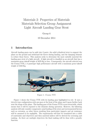
  • 1. Materials 2: Properties of Materials Materials Selection Group Assignment Light Aircraft Landing Gear Strut Group 6 19 December 2014 1 Introduction Aircraft landing gears can be split into 2 parts: the solid cylindrical strut to support the plane on the ground and withstand the forces during landing, and the damping element to reduce those forces. This analysis seeks to determine the most suitable material the landing gear strut of a light aircraft. A light aircraft is classified as an aircraft that has a maximum gross takeoff weight of 5670 Kg or less. Consequently, the aircraft selected was the Cessna TTX, a 4 passenger high performance aircraft with a maximum gross takeoff weight of 1633 Kg. Figure 1: Cessna TTX Figure 1 shows the Cessna TTX with its landing gear highlighted in red. It uses a tricycle type configuration with one gear at the front of the plane and 2 gears further back near the wings of the plane. The landing gear of the Cessna TTX is non-retractable, which means that it will be exposed to the elements during operation. However, the following analysis will only consider compressive axial loading of the strut and environmental factors such as corrosion, as other forces resulting from particulate impacts and air resistance will be assumed to be negligible. The requirements will first be translated into a table of constraints and objectives and then material indices will be derived for screening and ranking. As there are multiple objectives the final ranking will be done with a penalty function. 1
  • 2. Materials selection group 6 2 Translation Function Support the weight of a Cessna TTX aircraft during landing and while the plane is on the ground Constraints Specified length, L Minimum compressive strength Resist corrosion in water Resist buckling during landing Minimum fatigue endurance strength Moderately easy to manufacture Objectives Minimise weight Minimise material cost Free Variable Choice of material Cross-sectional area, A Table 1: Translation Many constraints and objectives were considered for our translation table. For ex- ample, the minimum service temperature of the material was considered but was not implemented because it proved unnecessary seeing as the constraint did not remove any materials. Hardness was also considered but was also rejected because any collision with airborne particles will be unlikely to cause localised damage that will harm the integrity of the structure. The primary objective of this design is to minimise weight as it affects the fuel con- sumption of the aircraft which leads to higher long-term running costs. The balance is that the savings due to a cheaper material might outweight the future fuel savings. 3 Screening 3.1 Compressive Strength & Corrosion After some research it was found that alloy steels and aluminium are the most common materials for this type of strut. Therefore, in order to immediately screen out materials that would be unsuitable for use on landing gear, a minimum compressive strength of 180MPa was applied, the lower limit stainless steels strength. This removed the weaker materials in the Edupack library such as bamboo and removed all foams and elastomers. Materials that were rated Limited Use or Unacceptable in fresh water we also screened out, since the Cessna TTX would most likely experience a damp environment during its life use, however, this only removed a very small number of materials. 3.2 Machinability In stage 4 of the selection process another screening was applied to remove anything with a rating for Formability, the ability of a material to be shaped or experience plastic deformation without being damaged, lower than 3 in order to cut down the remaining materials and so that the chosen material would be moderately easy to shape into the required form. Again, this only removed a small number of materials. The result of screening is shown below in Figure 2. 2
  • 3. Materials selection group 6 Figure 2: Screening based on minimum compressive strength 4 Ranking 4.1 Buckling By using the equations for the mass of a column, the minimum buckling load of a column and the fatigue equation, two material indices can be calculated by eliminating the free variable of the cross-sectional area. To find an index that will minimise the mass of the strut while maximising its minimum bucking load, it is necessary to find an expression for the cross-sectional area as a function of the mass, and rearrange the column buckling equation to find another expression for the area. The mass of a column is defined as: m = ρAL, (1) and therefore: A = m ρL (2) Meanwhile, the expression for the minimum buckling load of a column, according to the Euler Column Buckling formula, is F = π2 EI L2 , (3) where I is the area moment of inertia which, for a solid cylinder is defined as: I = πr4 4 = A2 4π (4) Therefore, F = πEA2 4L2 (5) 3
  • 4. Materials selection group 6 A = 4FL2 πE (6) m = ρ √ E 2L F π (7) Therefore, the required material index is: M1 = ρ √ E , (8) 4.2 Fatigue Strength In order to calculate the material index to minimise the mass of the strut while maximising the endurance toughness, it was necessary to first rearrange the fatigue equation to find an expression for the cross-sectional area as a function of the fatigue endurance, and then equate it with the expression for area as a function of mass. σe = F A (9) A = A σe (10) m = ρ σe F L (11) This produces the material index: M2 = ρ σe , (12) Then, the two indices are plotted together on the bubble plot in Figure 3, with M2 on the X-axis and M1 on the Y-axis. In order to minimise the mass while maximising the buckling resistance and fatigue endurance, materials in the lower left of the chart must be selected, as lower values of M1 and M2 indicate a high endurance and buckling resistance relative to the density of the material. The selection curve was moved into a position where stainless steel is on the outer edge, meaning that only other equal or superior materials are left for selection. 4.3 Cost More materials were removed by forming a second bubble plot that shows the material cost per kilogram in relation to buckling strength and fatigue endurance. The material indices for cost were the same as for mass but with ρ replaced by ρCM . The lower left corner of the bubble plot is shown in Figure 4. The pink and yellow bubbles represent several varieties of glass and ceramics respectively, both of which were screened out in stage 4 by removing materials with poor manufacturability. A selection line was drawn and moved to screen out several less desirable materials: such as Zirconia, which requires a long and costly machining process to achieve the desired shape; Titanium alloys, which are too brittle and expensive; and CFRP, which has low performance in moist and high fatigue environments. 4
  • 5. Materials selection group 6 Figure 3: Ranking based on specific fatgiue endurance and specific buckling strength Figure 4: Ranking based on cost, fatigue endurance and buckling strength The final step was to minimise the cost and weight of the material. Figure 5 shows dotted lines to indicate potential penalty function lines where α = 300. The clear winning material was cast magnesium alloy, since it is one of the lightest and cheapest materials, and is easier to manufacture compared to wrought magnesium alloy. 5 Discussion Magnesium alloys are already used in the aerospace industry, but in limited amounts. They account for 1.0-1.5% of the average aircraft’s weight, whereas the most common materials used for landing gear are strong and ductile specialist steels [1] and aluminium alloys [2]. In fact, materials for aerospace are usually selected for having a high strength- to-weight ratio and a high specific stiffness [3]. These are properties which were ranked for in this project, meaning that the method by which the magnesium alloy was selected is similar to that by which steels were chosen in industry. It is possible that errors were made in this selection process. For example, it is important to note that the sources used in this 5
  • 6. Materials selection group 6 Figure 5: Ranking based on cost and density analysis of the elected material predate the development of many composite materials, and there is a strong trend in the aerospace industry towards the use of composite materials. It is also significant that Edupack measures the fatigue endurance as the fatigue stress for a fatigue life of 107 cycles, whereas many forged aluminium landing gears demonstrate lifespans of less than 6000 cycles, although these tests were carried out on much larger commercial aircraft [2]. However, magnesium alloys are becoming increasingly prevalent in aerospace applications and their limited use is more likely a result of implementational inertia. Their many advantages include that they are cheaper than steel and lighter than both steel and aluminium [4]. It is also easier to produce than aluminium alloys; which must be heat treated, quenched and then aged by heat. The process by which aluminium alloys are produced often distorts the metal, requiring correction by rolling [4]. 6 Conclusion In conclusion, the material best suited for use in a light aircraft landing strut is a cast magnesium alloy, due to its superior mechanical properties, low weight and cost. Although it is a newer material that is relatively untested for such an application, the data recording its advantages is clear and it will likely form a much larger percentage of the weight of aircraft in the future. References [1] Alexandru Nica Mechanics of Aerospace Materials. Elsevier Scientific Publishing Com- pany, 1st edition, 1981. [2] Alfred M Freudenthal Fatigue in Aircraft Structures. Academic Press Inc, 1st edition, 1956. [3] Darrol Stinton The Anatomy of the Aeroplane. Blackwell Science Ltd, 2nd edition, 1998. [4] CES Edupack datahseets. CES, 2014. 6