SlideShare a Scribd company logo
1 of 10
Download to read offline
Westward Seafood’s/Ounalashka Corporation
Wind Data Assessment Report
Final Report
August 1, 2009-Unalaska, Alaska
Tower 1 SW Ridge Site-erected September 13, 2006 (data base changed September 16 and
September 21, 2006)*. Tower 1 was lowered and rewired in July 2008.
Site Description South West Corner –Pyramid Valley Ridge
Latitude/Longitude 53 50.0 North 166 31.0 West
Site Elevation 250 Feet
Load Logger and Tower Second Wind Load logger- 100 Foot NRG
Tower
DATA SYN0PIS
There are two NRG 30 meter metrological towers installed. One tower is on Westward
property (T1) and one on the adjoining property of the Ounalashka Corporation (T2). At each
site there is installed a 100’ (30 meters) guyed tower with three wind anemometers, wind
vane and temperature devices collecting data 24 hours. The wind speed anemometer at
100’ C1 has backup recording equipment at 100’ C2 and there is a third anemometer
installed at 66’ (20 meters) to evaluate wind speed and potential wind shear. The wind vane
is installed at the elevation of 80’. The data is being collected into a data base logger provided
by Second Wind Software. The data is being collected on an average interval of ten minutes.
The temperature gauge on Tower 1 was destroyed in a wind storm last winter (February
2008) and not replaced. The daily temperature data is available on Tower 2.
Each site has solar panel charger connected to a 12 volt battery and a backup 9.3 volt
alkaline battery. The wind information is recorded every 10 minutes and stored into flash
memory on site and is being down loaded weekly to a laptop computer. The flash memory ha
s data capacity of three plus years.
The Second Wind Software provides wind speed and direction for any period or time. The
time being used is Greenwich Mean Time GMT (-9 hrs) or Alaska Standard Time. The data is
being collected and reported in increments of 10 minute average time. For the purpose of
this report data will be collected and reported on a monthly basis and added monthly to the
year-to-date data base. The contract provides for a data collection period of 36 months for
Tower 1---Tower 2 was relocated to the ridge South-East of Tower 1. Tower 2 will have two
different data bases from the different locations.
The Second Wind Software also provides general information on power production capability
at each site, average speed, daily hourly wind availability (Diurnal Information) and wind direc
tion, temperature, daily, weekly and YTD energy information on a sample generator or on spe
cific generating equipment. Please note any wind turbine manufactures power curve informat
ion can be added to the software for any generator type or size. The present energy report
is utilizing the TMA 250 generator (250 Kw) power curve information provided by the
manufacturer and a comparative 250 Kw propeller type (NED) generator. This generator
comparison utilizes only data from Tower 1 located on Westward property erected in
September 2006. Wind availability is also being collected and analyzed from Tower 2 and
compared to wind availability from Tower 1 reinstalled in July 2008.
The 30 meter met towers and data loggers have been furnished by the Alaska Energy
Authority under their wind energy assessment program. Information from the assessment
report is public information and can be obtained from the consultant or the Alaska Energy
Authority.
Ounalashka Corporation Tower 2 Site
Tower 2 Pyramid Lake Site-Erected July 2008
Site Description Old military lake reservoir Pyramid Valley
Latitude/Longitude 53 59’9 North 166 33’44 West
Site Elevation 350 Feet
Load Logger and Tower Second Wind Load logger- 100 Foot NRG
Tower
A partnership between Ounalashka Corporation and Westward Seafood’s was developed to
share wind information on adjoining land. The current location of Tower 2 is near the old
military lake reservoir on the ridge above OSI and Westward. The site has ready access
from an old military road to the lake and is located on land owned by the Ounalashka Corpora
tion.
Wind Classes
Please note the following definition of wind classes attached to this report by the American
Wind Association. The article by the American Wind Association on the “Basic Principles of
Wind” outlines the different classes of wind for power production.
Basic Principles of
Wind Resource Evaluation
Wind resource evaluation is a critical element in projecting turbine performance at a given site.
The energy available in a wind stream is proportional to the cube of its speed, which means that
doubling the wind speed increases the available energy by a factor of eight. Furthermore, the
wind resource itself is seldom a steady, consistent flow. It varies with the time of day, season,
height above ground, and type of terrain. Proper siting in windy locations, away from large
obstructions, enhances a wind turbine's performance.
In general, annual average wind speeds of 5 meters per second (11 miles per hour) are required
for grid-connected applications. Annual average wind speeds of 3 to 4 m/s (7-9 mph) may be
adequate for non-connected electrical and mechanical applications such as battery charging and
water pumping. Wind resources exceeding this speed are available in many parts of the world.
Wind Power Density is a useful way to evaluate the wind resource available at a potential site.
The wind power density, measured in watts per square meter, indicates how much energy is
available at the site for conversion by a wind turbine. Classes of wind power density for two
standard wind measurement heights are listed in the table below. Wind speed generally increases
with height above ground.
Classes of Wind Power Density at 10 m and 50 m(a)
.
10 m (33 ft)
50 m (164 ft)
Wind
Power
Class
Wind
Power
Density
(W/m2 )
Speed (b)
m/s (mph)
Wind
Power
Density
(W/m2 )
Speed (b)
m/s (mph)
1
<100
<4.4 (9.8)
<200
<5.6 (12.5)
2
100 - 150
4.4 (9.8)/5.1 (11.5)
200 - 300
5.6 (12.5)/6.4 (14.3)
3
150 - 200
5.1 (11.5)/5.6 (12.5)
300 - 400
6.4 (14.3)/7.0 (15.7)
4
200 - 250
5.6 (12.5)/6.0 (13.4)
400 - 500
7.0 (15.7)/7.5 (16.8)
5
250 - 300
6.0 (13.4)/6.4 (14.3)
500 - 600
7.5 (16.8)/8.0 (17.9)
6
300 - 400
6.4 (14.3)/7.0 (15.7)
600 - 800
8.0 (17.9)/8.8 (19.7)
7
>400
>7.0 (15.7)
>800
>8.8 (19.7)
(a) Vertical extrapolation of wind speed based on the 1/7 power law
(b) Mean wind speed is based on the Rayleigh speed distribution of equivalent wind power density. Wind speed is for standard sea-level conditions. To maintain the same power density, speed increases 3%/1000 m (5%/5000 ft) of elevation.
(from the Battelle Wind Energy Resource Atlas)
In general, sites with a Wind Power Class rating of 4 or higher are now preferred for large scale wind plants. Research conducted by industry and the U.S. government
is expanding the applications of grid- connected wind technology to areas with more moderate wind speeds.
Wind data for the NRG Towers is being collected at 20 meters (66’) and 30 meters (100’).
© 1998 by the American Wind Energy Association.
May be freely distributed provided this notice is included.
All other rights reserved.
June 2009 Assessment Report
In July 2008 Tower 1 was lowered and the wind anemometers and weather vane were rewired.
The data logger was not operating and was returned to Second
Wind for evaluation. It was determined that the wet cell battery had failed. The data logger was reinstalled at the end of July
with a new battery.
In September
the data logger on T1 encountered additional voltage issues and the battery was exchanged with the T2 battery. The issue seems to be resolved but will require
constant monitoring. On June 24, 2009 the T1 system shut down with a continuing voltage issue. No attempt is being made to repair the system with the
termination of
the study by Westward Seafood on May 31, 2009.
The June, July and August 2007 monthly wind was at the lowest velocity when compared to the previous months of the study. Give
n the historical wind data,
June and July
are the normal months with the lowest wind velocity and average wind strength.
Information from Tower 2 in July 2008 and from Tower 1 and
Tower 2 i
n August supports the lower summer wind velocities. It is interesting to note on the August 2008 “Diurnal Graphs” that during the peak
evening hours
of 6:00PM to 9:00PM there
still was economic wind speeds (12 MPH) for energy production.
In September 2008 the lower wind velocities continued when compared to the prior years
. The wind capacity factor was 16% for September 2008 and 30% for
September 2007.
In mid-October the data logger failed on Tower 2 and was returned to Second Wind for repairs.
The data logger for Tower 2 was reinstalled at
the end of November
2008.
Vertical Axis Generation comparison to Horizontal Axis Generation
Westward Seafood’s has elected to consider a vertical axis generator developed by TMA in Wyoming as an option. The consultant
received the power curve
information from TMA on their 2
50Kw vertical axis generator during the month of July 2007. The consultant has incorporated the TMA power curve information
i
n
to each of the monthly study periods. The consultant has selected a NED 250 Kw propeller (horizontal axis) type generator for comparative analysis.
The
NED
wind turbine power curve was included with the Second Wind Software.
Any manufactures wind turbine power curve data can be added to the software for
calculating the energy production from the respective generating unit.
In an e-mail received from TMA the following comments have been received.
The following information is from Scott Taylor of TMA, Inc on July 27, 2007:
“My thoughts regarding the differences in the capacity factors of the TMA turbine and a similarly rated prop turbine are as follows:
The referenced prop turbine has a rotor swept area = 710 m2, while the referenced TMA turbine has a rotor swept area = 285 m2
. The prop has a 2.5X larger rotor swept area, therefore having
the ability to capture more energy from the wind. Above 20 mph, the TMA wind turbine is more efficient and is converting more kW per unit of rotor swept area, but has trouble overcoming the
large difference in rotor swept area. The formula for energy conversion of a turbine is:
Power = ½ x air density x rotor swept area x wind speed3 x turbine efficiency
The rotor swept area has a linear affect on the power conversion. Based on the cube effect of the wind speed, the TMA turbine can make up production in the higher wind speeds where the prop
efficiency drops and shuts down.
The referenced prop power curve shows a cut-out wind speed of 55 mph. In my experience, I haven’t seen a prop turbine in the 250 kW rated size, or larger for that matter, operate above 45
mph in the type of terrain that we are evaluating.
Although wind speed data is a good indicator of the power production available at a site, there are other factors that really should be considered in the evaluation.
Turbulence Intensity (TI)
: In general, it is a quantity that characterizes the intensity of gusts in the airflow. The CPP engineers have indicated that most prop manufacturers won’t even consider
placing their turbines in locations with turbulence intensities greater than 15%. Higher TI’s adversely affect the performance of the turbine and can cause excessive loads on the blades which
require shutting down the turbine at wind speeds below the cut-out speed to prevent damage. This should not be a problem for the TMA design.
Wind Shear
: The local variation of the wind vector in a given direction, i.e. change in wind speed with change in height. Excessive wind shear can also cause highly fluctuating blade load
conditions on props that may cause them to be shut down prematurely to prevent damage. It may also affect the aerodynamic performance of the rotor. This should not be a problem for the
TMA design.
Turbine Availability
: Dick’s numbers are based wind availability and on the turbines being available to operate 100% of the time that the wind is sufficient for production. I would argue that the
TMA turbine would have a higher turbine availability than a prop based on the robust design of the TMA turbine. The TMA turbine would require less downtime for maintenance and would
continue to operate in conditions that would require a prop to be shut down to prevent possible damage.
With the generator technology that we may incorporate into the turbine, the TMA power curve may not have to be “flattened out” above rated wind speeds and may continue up the available
curve until the cut-out wind speed is reached. This ability will greatly increase the amount of kWh produced by the TMA turbine
”.
The following comparison is the (Tower 1) monthly and Period to Date wind capacity information for power production from both types of
generating
units:
NED 250Kw Wind Turbine (Propeller)
Month Capacity* Capacity* Capacity*
1st Year (2006) 2nd Year (2007) 3rd Year (2008)
October 43% 29% 28%
November 49% 39% 33%
December 40% 30% 36%
January 40% 39% 25%
February 34% 30% 41%
March 40% 33% 45%
April 27% N/A 36%
May 27% N/A 14%
June 23% N/A 18%
July 6% N/A -
August 17% 9% -
September 44% 16% -
Period-To-Date
Kwh
31%
667,354
28%
399,588
31%
422,110
TMA 250Kw Vertical Axis Turbine
Month Capacity* Capacity* Capacity*
1st Year (2006) 2nd Year (2007) 3rd Year (2008)
October 27% 9% 16%
November 29% 22% 21%
December 15% 17% 21%
January 25% 21% 13%
February 19% 16% 25%
March 21% 20% 25%
April 13% N/A 20%
May 12% N/A 6%
June 10% N/A 7%
July 3% N/A -
August 8% 4% -
September 26% 7% -
Period-To-Date
Kwh 17%
362,743
15%
215,918
17%
222,418
Wind Capacity*
*The wind capacity information is calculated based on the amount of actual Kwh produced for the period noted (based on the manufactures power curves
) and
compared to
the maximum Kwh that could be produced for each period. The wind capacity formula is hours of the period times the generator’s output capacity
(
8
,760 hrs X 250 Kw) equals (2,190,000 Kwh) maximum YTD energy. The amount of Kwh actually produced (based on the manufactures power curves)
during
the YTD period i
s then divided by the maximum Kwh that could be generated to determine wind capacity. I; E, 667,354/2,190,000Kwh =s 31% wind capacity
f
or the first 12 months
of the study period. These Kilowatt-hours produced are based on the wind capacity during the initial twelve month study period.
The
above
Tower 1 data covers 32 months of the study period.
Average monthly wind capacity for the NED generator at the T1 location is 31% (winds above 7 MPH and below 55 MPH) during the initial 12 months
study
period
(Oct 2006-Sept 2007). During the 2008-09 study period wind capacity has averaged 27% for the Ned Generator. This average wind capacity
information
is based
on the NED 250Kw turbine power curves as utilized by the Second Wind Software.
Average monthly wind capacity for the TMA generator at the T1 location is 17% (winds above 10 MPH and below 60 MPH) during the first 12 months study
perio
d
(Oct 2006-Sept 2007) and 15% for the TMA unit during the second year of the study period. This wind capacity information is based on the TMA
250Kw
generator
power curve as added to the Second Wind Software. The second year of the study period utilized only eight months of actual data. In the present stu
d
y
period (July 2008-June 2009) wind capacity is averaging 17% for the TMA 250Kw VAT.
I would note there is some wind shear recorded at Tower 1 for the past monitoring periods. Wind shear or wind differential is noted between C1
at 30 meters
and wind velocities at
15 meters for C3. It is interesting to note that Tower 1 and Tower 2 have experienced class 5 to 7 winds during the study period.
Also attached is the period-to-date summary of wind direction for the Tower 2 site since July 2008. During the first 12 month study period (Oct 2006-Sept 2007)
T
ower 1
wind was from the North in general 48% of the time. The most prevalent wind direction was from the due North at 23% of the period hours.
During the
current 12 month study
the wind was predominately from the South, with South West wind was the most prevalent at 16% of the hours.
One report that is not printed is the hourly wind speed graph that is available in a scroll format for each month or the entire study period.
The average speed
data is recorded at 10
minute average increments 24/7.
Available Wind Capacity Comparison between Towers (based on a NED 250 Kw wind Turbine) propeller type
Month Tower 1 Capacity* Energy Tower 2 Capacity* Energy
July 2008 (17%) (29,202 Kwh) 17% 29,202 Kwh
August 9% 15,008 Kwh 9% 15,008 Kwh
September 16% 28,074 Kwh 16% 28,942 Kwh
October 28% 49,749 Kwh (28%) (49,749 Kwh)
November 33% 57,980 Kwh (33%) (57,980 Kwh)
December 36% 63,539 Kwh (36)% (63,539 Kwh)
January 25% 45,505 Kwh 26% 47,455 Kwh
February 41% 68,672 Kwh 40% 67,534 Kwh
March
45% 84,440 Kwh 45% 83,692 Kwh
April 36% 64,047 Kwh 38% 68,549 Kwh
May 14% 24,432 Kwh 12% 22,049 Kwh
June (18%) 32,478 Kwh 18% 32,478 Kwh
Average Wind Capacity
for
study period
27% 27%
Average Energy
For study period
563,126 Kwh 566,177 Kwh
*Percentage of the monthly hours that wind is available for power production. July data from Tower 2 was incorporated into the Tower 1 data set and utilized
for
report
ing purposes (Tower 1 data is mirroring Tower 2). In October, November and December
data from Tower 1 is inserted into Tower 2 data set for reporting
purposes. There is very little difference in the
actual wind velocity data between towers. Note the actual data from January, February, March, April, May
and
June
2009.
Attached are the copies of the June 2009 graphs from Tower 2 and wind direction summaries for the study period.
The study to date has indicated economic
wind values from September
2006 through June 2009 in excess of 12 MPH (Class 4) from Tower 1. The new Tower 2 location is mostly
a mirror image of data
being collected from Tower 1. Please note the data from T
ower 1 and Tower 2 in the above graph
The consultant would like to note the two 30 Meter towers and all equipment for the wind assessment study has been supplied
by the Alaska Energy Authority
under their wind program.
The consultant is very appreciative of the support and recommendations of the AEA staff during the wind assessment study period.
Data can be exported in a raw format in an “Excel” spreadsheet from the data base collected over the study periods.
The consultant Richard G. Peck can be reached by e-mail: rgpeck@hotmail.com or phone at 907.395.0333 or cell phone 907.741.2131.
The information from
the study can be obtained from the consultant or the Alaska Energy Authority.
Final Wind Assessment Report
Westward Seafood’s—Ounalashka Corporation
August 1, 2009
The (Westward Seafood’s-Ounalashka Corporation) wind assessment study for Pyramid Valley was concluded on June 30, 2009. The joint (Westward-OC) wind assessment
w
as for a period of one year and consisted of two
NRG 30 meter metrological towers erected on their adjoining Pyramid Valley lands.
The study area in Pyramid Valley had
excellent access on a ridge that ran in a North-Northwest to an East-Southeast direction.
Tower 1 was located at an elevation of 250’ at the Latitude 53 50.0 North and L
ongitu
de
166 3.0 West. Tower 2 was re-located at elevation of 350’ at the Latitude 53 59’9 North and L ongitude 66 33’44 West on “OC” land.
The towers and the associated
equipment were provided by the Alaska Energy Authority under their wind
tower loan program. The data loggers were manufactured by Second Wind, Inc.
The data was
collated and analyzed utilizing Second Winds’ “Nomad Software”. The
thirty-three month data from Tower 1 and twelve month data from Tower 2
has been also collected in its
raw format and is available in “Excel” spreadsheets.
The initial Westward wind assessment study started on October 2006. Tower 2 was initially installed at a lower elevation on Westward land and then relocated
to Ounalashka
Corporation land
in July 2008. Tower 2 at its initial location had winds approximate 30% less capacity when compared to Tower 1 during the first two years of the study. The
To
wer 2
wind speed at lower Westward elevation location has limited economic value.
The three year long Westward wind assessment study indicates that the monthly wind capacity has varied form a high of 49% in the winter and a low of 9%
during the
summer months
. The average yearly wind capacity during the study period was 30% at the Westward Tower 1 site. The average 30% wind capacity data
at the Tower 1
location is
based on wind speeds that are above 7 MPH and below 55 MPH.
Tower 1 and Tower 2 wind speeds and direction are a virtual mirror imagine of each other during
the past year’s
joint study.
The wind power class has averaged about Class 4 (5.6 to 6.0 M/S) or 12 MPH for the entire thirty-three month study period
according to the “American Wind Energy
Association” classification
system. June, July and August are the months with the lowest average wind capacity of about 18% during the 33 month study period .
The nine
months of October through May
often experience Class 5-7 winds, wind speeds that average in excess of 14 mph or 6.2 M/S. Note Chart
1-average wind speed for the
past thirty –three months for Westwards Tower 1 location.
Winds in Pyramid Valley have been strongly directional from the North-23% in Year one, 15% in Year two and 14% in the third year. The Pyramid Valley wind flow was not
alw
ays
laminar and wind shear was experienced
on several occasions. In depth wind shear information can be obtained by analyzing wind data form the C1-C2 anemometer (30
meters) and comparing it to the wind speeds recorded from the C-3 anemometer located at
(15 meters). There were minimal
icing conditions experienced during the study
periods due to the low elevations of the Towers at an approximate height of
about 300’ MSL. Note Chart 2-wind rose major wind directions for the Tower 1-Averaged
Nort
h 16.5%
of the time for the thirty-three month study period.
The maximum wind gust speed recorded during the study period was 98 MPH. In contacting the local weather bureau at the Dutch Harbor Airport (PADU) their records indicate
a maximum recorded wind gust of 98 Knots or
126 MPH recorded in 1995.

More Related Content

What's hot

IRJET- A Review of Power Control Strategies for DFIG based Wind Energy Conver...
IRJET- A Review of Power Control Strategies for DFIG based Wind Energy Conver...IRJET- A Review of Power Control Strategies for DFIG based Wind Energy Conver...
IRJET- A Review of Power Control Strategies for DFIG based Wind Energy Conver...IRJET Journal
 
Proposed Wind Power System in Pyay District in Myanmar
Proposed Wind Power System in Pyay District in MyanmarProposed Wind Power System in Pyay District in Myanmar
Proposed Wind Power System in Pyay District in Myanmarijtsrd
 
Design Construction, Simulation and Testing of A 300W Wind-Powered Battery Ch...
Design Construction, Simulation and Testing of A 300W Wind-Powered Battery Ch...Design Construction, Simulation and Testing of A 300W Wind-Powered Battery Ch...
Design Construction, Simulation and Testing of A 300W Wind-Powered Battery Ch...theijes
 
Optimal fuzzy-PID controller with derivative filter for load frequency contro...
Optimal fuzzy-PID controller with derivative filter for load frequency contro...Optimal fuzzy-PID controller with derivative filter for load frequency contro...
Optimal fuzzy-PID controller with derivative filter for load frequency contro...IJECEIAES
 
Modeling of Wind Energy on Isolated Area
Modeling of Wind Energy on Isolated AreaModeling of Wind Energy on Isolated Area
Modeling of Wind Energy on Isolated AreaIJPEDS-IAES
 
Review of different Fault Ride through (FRT) Control Strategies for a DFIG Wi...
Review of different Fault Ride through (FRT) Control Strategies for a DFIG Wi...Review of different Fault Ride through (FRT) Control Strategies for a DFIG Wi...
Review of different Fault Ride through (FRT) Control Strategies for a DFIG Wi...IRJET Journal
 
Modeling and simulation of dfig to grid connected wind power generation using...
Modeling and simulation of dfig to grid connected wind power generation using...Modeling and simulation of dfig to grid connected wind power generation using...
Modeling and simulation of dfig to grid connected wind power generation using...IAEME Publication
 
Fuzzy Logic Pitch Control of Variable Speed Wind Turbine
Fuzzy Logic Pitch Control of Variable Speed Wind TurbineFuzzy Logic Pitch Control of Variable Speed Wind Turbine
Fuzzy Logic Pitch Control of Variable Speed Wind TurbineIRJET Journal
 
Active and Reactive Power Control of a Doubly Fed Induction Generator
Active and Reactive Power Control of a Doubly Fed Induction GeneratorActive and Reactive Power Control of a Doubly Fed Induction Generator
Active and Reactive Power Control of a Doubly Fed Induction GeneratorIJPEDS-IAES
 
Modeling and Control of a Doubly-Fed Induction Generator for Wind Turbine-Gen...
Modeling and Control of a Doubly-Fed Induction Generator for Wind Turbine-Gen...Modeling and Control of a Doubly-Fed Induction Generator for Wind Turbine-Gen...
Modeling and Control of a Doubly-Fed Induction Generator for Wind Turbine-Gen...IJPEDS-IAES
 
10 wind turbine_generators
10 wind turbine_generators10 wind turbine_generators
10 wind turbine_generatorslakshmi durga
 
Design and Simulation Analysis of Outer Stator Inner Rotor DFIG by 2d and 3d ...
Design and Simulation Analysis of Outer Stator Inner Rotor DFIG by 2d and 3d ...Design and Simulation Analysis of Outer Stator Inner Rotor DFIG by 2d and 3d ...
Design and Simulation Analysis of Outer Stator Inner Rotor DFIG by 2d and 3d ...Mellah Hacene
 
IRJET - Thermoelectric Power Generation by Bike Silencer
IRJET - Thermoelectric Power Generation by Bike SilencerIRJET - Thermoelectric Power Generation by Bike Silencer
IRJET - Thermoelectric Power Generation by Bike SilencerIRJET Journal
 
Dynamic behavior of DFIG wind turbine under grid fault conditions (1)
Dynamic behavior of DFIG wind turbine under grid fault conditions (1)Dynamic behavior of DFIG wind turbine under grid fault conditions (1)
Dynamic behavior of DFIG wind turbine under grid fault conditions (1)Asoka Technologies
 
Design and analysis of an external rotor internal-stator doubly fed induction...
Design and analysis of an external rotor internal-stator doubly fed induction...Design and analysis of an external rotor internal-stator doubly fed induction...
Design and analysis of an external rotor internal-stator doubly fed induction...Mellah Hacene
 
3.10 eet in electrical systems
3.10 eet in electrical systems3.10 eet in electrical systems
3.10 eet in electrical systemsAnup Kiran
 
Development of controller for economic load dispatch by generating units und
Development of controller for economic load dispatch by generating units undDevelopment of controller for economic load dispatch by generating units und
Development of controller for economic load dispatch by generating units undIAEME Publication
 
001 160718 energy systems for green buildings20160718-2
001 160718 energy systems for green buildings20160718-2001 160718 energy systems for green buildings20160718-2
001 160718 energy systems for green buildings20160718-2senicsummerschool
 

What's hot (20)

IRJET- A Review of Power Control Strategies for DFIG based Wind Energy Conver...
IRJET- A Review of Power Control Strategies for DFIG based Wind Energy Conver...IRJET- A Review of Power Control Strategies for DFIG based Wind Energy Conver...
IRJET- A Review of Power Control Strategies for DFIG based Wind Energy Conver...
 
Proposed Wind Power System in Pyay District in Myanmar
Proposed Wind Power System in Pyay District in MyanmarProposed Wind Power System in Pyay District in Myanmar
Proposed Wind Power System in Pyay District in Myanmar
 
Design Construction, Simulation and Testing of A 300W Wind-Powered Battery Ch...
Design Construction, Simulation and Testing of A 300W Wind-Powered Battery Ch...Design Construction, Simulation and Testing of A 300W Wind-Powered Battery Ch...
Design Construction, Simulation and Testing of A 300W Wind-Powered Battery Ch...
 
Optimal fuzzy-PID controller with derivative filter for load frequency contro...
Optimal fuzzy-PID controller with derivative filter for load frequency contro...Optimal fuzzy-PID controller with derivative filter for load frequency contro...
Optimal fuzzy-PID controller with derivative filter for load frequency contro...
 
Modeling of Wind Energy on Isolated Area
Modeling of Wind Energy on Isolated AreaModeling of Wind Energy on Isolated Area
Modeling of Wind Energy on Isolated Area
 
Review of different Fault Ride through (FRT) Control Strategies for a DFIG Wi...
Review of different Fault Ride through (FRT) Control Strategies for a DFIG Wi...Review of different Fault Ride through (FRT) Control Strategies for a DFIG Wi...
Review of different Fault Ride through (FRT) Control Strategies for a DFIG Wi...
 
Modeling and simulation of dfig to grid connected wind power generation using...
Modeling and simulation of dfig to grid connected wind power generation using...Modeling and simulation of dfig to grid connected wind power generation using...
Modeling and simulation of dfig to grid connected wind power generation using...
 
Fuzzy Logic Pitch Control of Variable Speed Wind Turbine
Fuzzy Logic Pitch Control of Variable Speed Wind TurbineFuzzy Logic Pitch Control of Variable Speed Wind Turbine
Fuzzy Logic Pitch Control of Variable Speed Wind Turbine
 
Improved Performance of DFIG-generators for Wind Turbines Variable-speed
Improved Performance of DFIG-generators for Wind Turbines Variable-speedImproved Performance of DFIG-generators for Wind Turbines Variable-speed
Improved Performance of DFIG-generators for Wind Turbines Variable-speed
 
D03701028034
D03701028034D03701028034
D03701028034
 
Active and Reactive Power Control of a Doubly Fed Induction Generator
Active and Reactive Power Control of a Doubly Fed Induction GeneratorActive and Reactive Power Control of a Doubly Fed Induction Generator
Active and Reactive Power Control of a Doubly Fed Induction Generator
 
Modeling and Control of a Doubly-Fed Induction Generator for Wind Turbine-Gen...
Modeling and Control of a Doubly-Fed Induction Generator for Wind Turbine-Gen...Modeling and Control of a Doubly-Fed Induction Generator for Wind Turbine-Gen...
Modeling and Control of a Doubly-Fed Induction Generator for Wind Turbine-Gen...
 
10 wind turbine_generators
10 wind turbine_generators10 wind turbine_generators
10 wind turbine_generators
 
Design and Simulation Analysis of Outer Stator Inner Rotor DFIG by 2d and 3d ...
Design and Simulation Analysis of Outer Stator Inner Rotor DFIG by 2d and 3d ...Design and Simulation Analysis of Outer Stator Inner Rotor DFIG by 2d and 3d ...
Design and Simulation Analysis of Outer Stator Inner Rotor DFIG by 2d and 3d ...
 
IRJET - Thermoelectric Power Generation by Bike Silencer
IRJET - Thermoelectric Power Generation by Bike SilencerIRJET - Thermoelectric Power Generation by Bike Silencer
IRJET - Thermoelectric Power Generation by Bike Silencer
 
Dynamic behavior of DFIG wind turbine under grid fault conditions (1)
Dynamic behavior of DFIG wind turbine under grid fault conditions (1)Dynamic behavior of DFIG wind turbine under grid fault conditions (1)
Dynamic behavior of DFIG wind turbine under grid fault conditions (1)
 
Design and analysis of an external rotor internal-stator doubly fed induction...
Design and analysis of an external rotor internal-stator doubly fed induction...Design and analysis of an external rotor internal-stator doubly fed induction...
Design and analysis of an external rotor internal-stator doubly fed induction...
 
3.10 eet in electrical systems
3.10 eet in electrical systems3.10 eet in electrical systems
3.10 eet in electrical systems
 
Development of controller for economic load dispatch by generating units und
Development of controller for economic load dispatch by generating units undDevelopment of controller for economic load dispatch by generating units und
Development of controller for economic load dispatch by generating units und
 
001 160718 energy systems for green buildings20160718-2
001 160718 energy systems for green buildings20160718-2001 160718 energy systems for green buildings20160718-2
001 160718 energy systems for green buildings20160718-2
 

Similar to Westward Ounalashka Final Report R1

The stable atmospheric boundary layer a challenge for wind turbine operatio...
The stable atmospheric boundary layer   a challenge for wind turbine operatio...The stable atmospheric boundary layer   a challenge for wind turbine operatio...
The stable atmospheric boundary layer a challenge for wind turbine operatio...ndkelley
 
IRJET - Measurement and Analysis of the Voltage Current Characteristic of a M...
IRJET - Measurement and Analysis of the Voltage Current Characteristic of a M...IRJET - Measurement and Analysis of the Voltage Current Characteristic of a M...
IRJET - Measurement and Analysis of the Voltage Current Characteristic of a M...IRJET Journal
 
IRJET- A Revieiw of Wind Energy Potential in Kano State, Nigeria for the ...
IRJET-  	  A Revieiw of Wind Energy Potential in Kano State, Nigeria for the ...IRJET-  	  A Revieiw of Wind Energy Potential in Kano State, Nigeria for the ...
IRJET- A Revieiw of Wind Energy Potential in Kano State, Nigeria for the ...IRJET Journal
 
Domestic Solar - Aero - Hydro Power Generation System
Domestic Solar - Aero - Hydro Power Generation SystemDomestic Solar - Aero - Hydro Power Generation System
Domestic Solar - Aero - Hydro Power Generation SystemIOSR Journals
 
RELIABILITY EVALUATION OF A WIND POWER PLANT IN THE MID REGION OF KARNATAKA S...
RELIABILITY EVALUATION OF A WIND POWER PLANT IN THE MID REGION OF KARNATAKA S...RELIABILITY EVALUATION OF A WIND POWER PLANT IN THE MID REGION OF KARNATAKA S...
RELIABILITY EVALUATION OF A WIND POWER PLANT IN THE MID REGION OF KARNATAKA S...IRJET Journal
 
Grand Renewable Energy Conference
Grand Renewable Energy ConferenceGrand Renewable Energy Conference
Grand Renewable Energy ConferenceKaushik Sharma
 
Wireless wetherstation
Wireless wetherstationWireless wetherstation
Wireless wetherstationMohan
 
Performance Analysis of Aerodynamic Design for Wind Turbine Blade
Performance Analysis of Aerodynamic Design for Wind Turbine BladePerformance Analysis of Aerodynamic Design for Wind Turbine Blade
Performance Analysis of Aerodynamic Design for Wind Turbine BladeIRJET Journal
 
Nwtc turb sim workshop september 22 24, 2008- boundary layer dynamics and wi...
Nwtc turb sim workshop september 22 24, 2008-  boundary layer dynamics and wi...Nwtc turb sim workshop september 22 24, 2008-  boundary layer dynamics and wi...
Nwtc turb sim workshop september 22 24, 2008- boundary layer dynamics and wi...ndkelley
 
Wind Energy: Analysis and Application-Crimson Publishers
Wind Energy: Analysis and Application-Crimson PublishersWind Energy: Analysis and Application-Crimson Publishers
Wind Energy: Analysis and Application-Crimson PublishersCrimsonpublishersPRSP
 
Numerical simulation of Hybrid Generation System: a case study
Numerical simulation of Hybrid Generation System: a case studyNumerical simulation of Hybrid Generation System: a case study
Numerical simulation of Hybrid Generation System: a case studyIRJET Journal
 
Load Forecasting Using LSTM Model
Load Forecasting Using LSTM ModelLoad Forecasting Using LSTM Model
Load Forecasting Using LSTM ModelIRJET Journal
 
Feasibility Study of a Grid Connected Hybrid Wind/PV System
Feasibility Study of a Grid Connected Hybrid Wind/PV SystemFeasibility Study of a Grid Connected Hybrid Wind/PV System
Feasibility Study of a Grid Connected Hybrid Wind/PV SystemIJAPEJOURNAL
 

Similar to Westward Ounalashka Final Report R1 (20)

The stable atmospheric boundary layer a challenge for wind turbine operatio...
The stable atmospheric boundary layer   a challenge for wind turbine operatio...The stable atmospheric boundary layer   a challenge for wind turbine operatio...
The stable atmospheric boundary layer a challenge for wind turbine operatio...
 
Power from wind in india
Power from wind in indiaPower from wind in india
Power from wind in india
 
IRJET - Measurement and Analysis of the Voltage Current Characteristic of a M...
IRJET - Measurement and Analysis of the Voltage Current Characteristic of a M...IRJET - Measurement and Analysis of the Voltage Current Characteristic of a M...
IRJET - Measurement and Analysis of the Voltage Current Characteristic of a M...
 
Impact of field roughness and power losses, turbulence intensity on electrici...
Impact of field roughness and power losses, turbulence intensity on electrici...Impact of field roughness and power losses, turbulence intensity on electrici...
Impact of field roughness and power losses, turbulence intensity on electrici...
 
IRJET- A Revieiw of Wind Energy Potential in Kano State, Nigeria for the ...
IRJET-  	  A Revieiw of Wind Energy Potential in Kano State, Nigeria for the ...IRJET-  	  A Revieiw of Wind Energy Potential in Kano State, Nigeria for the ...
IRJET- A Revieiw of Wind Energy Potential in Kano State, Nigeria for the ...
 
Domestic Solar - Aero - Hydro Power Generation System
Domestic Solar - Aero - Hydro Power Generation SystemDomestic Solar - Aero - Hydro Power Generation System
Domestic Solar - Aero - Hydro Power Generation System
 
RELIABILITY EVALUATION OF A WIND POWER PLANT IN THE MID REGION OF KARNATAKA S...
RELIABILITY EVALUATION OF A WIND POWER PLANT IN THE MID REGION OF KARNATAKA S...RELIABILITY EVALUATION OF A WIND POWER PLANT IN THE MID REGION OF KARNATAKA S...
RELIABILITY EVALUATION OF A WIND POWER PLANT IN THE MID REGION OF KARNATAKA S...
 
47 iit powai_ppt
47 iit powai_ppt47 iit powai_ppt
47 iit powai_ppt
 
Grand Renewable Energy Conference
Grand Renewable Energy ConferenceGrand Renewable Energy Conference
Grand Renewable Energy Conference
 
Allen Report
Allen ReportAllen Report
Allen Report
 
Wireless wetherstation
Wireless wetherstationWireless wetherstation
Wireless wetherstation
 
Performance Analysis of Aerodynamic Design for Wind Turbine Blade
Performance Analysis of Aerodynamic Design for Wind Turbine BladePerformance Analysis of Aerodynamic Design for Wind Turbine Blade
Performance Analysis of Aerodynamic Design for Wind Turbine Blade
 
Nwtc turb sim workshop september 22 24, 2008- boundary layer dynamics and wi...
Nwtc turb sim workshop september 22 24, 2008-  boundary layer dynamics and wi...Nwtc turb sim workshop september 22 24, 2008-  boundary layer dynamics and wi...
Nwtc turb sim workshop september 22 24, 2008- boundary layer dynamics and wi...
 
Wind physics
Wind physicsWind physics
Wind physics
 
Learn about Wind Energy
Learn about Wind EnergyLearn about Wind Energy
Learn about Wind Energy
 
Wind Energy: Analysis and Application-Crimson Publishers
Wind Energy: Analysis and Application-Crimson PublishersWind Energy: Analysis and Application-Crimson Publishers
Wind Energy: Analysis and Application-Crimson Publishers
 
UNIT 3.pptx
UNIT 3.pptxUNIT 3.pptx
UNIT 3.pptx
 
Numerical simulation of Hybrid Generation System: a case study
Numerical simulation of Hybrid Generation System: a case studyNumerical simulation of Hybrid Generation System: a case study
Numerical simulation of Hybrid Generation System: a case study
 
Load Forecasting Using LSTM Model
Load Forecasting Using LSTM ModelLoad Forecasting Using LSTM Model
Load Forecasting Using LSTM Model
 
Feasibility Study of a Grid Connected Hybrid Wind/PV System
Feasibility Study of a Grid Connected Hybrid Wind/PV SystemFeasibility Study of a Grid Connected Hybrid Wind/PV System
Feasibility Study of a Grid Connected Hybrid Wind/PV System
 

Westward Ounalashka Final Report R1

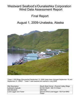
  • 1. Westward Seafood’s/Ounalashka Corporation Wind Data Assessment Report Final Report August 1, 2009-Unalaska, Alaska Tower 1 SW Ridge Site-erected September 13, 2006 (data base changed September 16 and September 21, 2006)*. Tower 1 was lowered and rewired in July 2008. Site Description South West Corner –Pyramid Valley Ridge Latitude/Longitude 53 50.0 North 166 31.0 West Site Elevation 250 Feet Load Logger and Tower Second Wind Load logger- 100 Foot NRG Tower
  • 2. DATA SYN0PIS There are two NRG 30 meter metrological towers installed. One tower is on Westward property (T1) and one on the adjoining property of the Ounalashka Corporation (T2). At each site there is installed a 100’ (30 meters) guyed tower with three wind anemometers, wind vane and temperature devices collecting data 24 hours. The wind speed anemometer at 100’ C1 has backup recording equipment at 100’ C2 and there is a third anemometer installed at 66’ (20 meters) to evaluate wind speed and potential wind shear. The wind vane is installed at the elevation of 80’. The data is being collected into a data base logger provided by Second Wind Software. The data is being collected on an average interval of ten minutes. The temperature gauge on Tower 1 was destroyed in a wind storm last winter (February 2008) and not replaced. The daily temperature data is available on Tower 2. Each site has solar panel charger connected to a 12 volt battery and a backup 9.3 volt alkaline battery. The wind information is recorded every 10 minutes and stored into flash memory on site and is being down loaded weekly to a laptop computer. The flash memory ha s data capacity of three plus years. The Second Wind Software provides wind speed and direction for any period or time. The time being used is Greenwich Mean Time GMT (-9 hrs) or Alaska Standard Time. The data is being collected and reported in increments of 10 minute average time. For the purpose of this report data will be collected and reported on a monthly basis and added monthly to the year-to-date data base. The contract provides for a data collection period of 36 months for Tower 1---Tower 2 was relocated to the ridge South-East of Tower 1. Tower 2 will have two different data bases from the different locations. The Second Wind Software also provides general information on power production capability at each site, average speed, daily hourly wind availability (Diurnal Information) and wind direc tion, temperature, daily, weekly and YTD energy information on a sample generator or on spe cific generating equipment. Please note any wind turbine manufactures power curve informat ion can be added to the software for any generator type or size. The present energy report is utilizing the TMA 250 generator (250 Kw) power curve information provided by the manufacturer and a comparative 250 Kw propeller type (NED) generator. This generator comparison utilizes only data from Tower 1 located on Westward property erected in September 2006. Wind availability is also being collected and analyzed from Tower 2 and compared to wind availability from Tower 1 reinstalled in July 2008. The 30 meter met towers and data loggers have been furnished by the Alaska Energy Authority under their wind energy assessment program. Information from the assessment report is public information and can be obtained from the consultant or the Alaska Energy Authority.
  • 3. Ounalashka Corporation Tower 2 Site Tower 2 Pyramid Lake Site-Erected July 2008 Site Description Old military lake reservoir Pyramid Valley Latitude/Longitude 53 59’9 North 166 33’44 West Site Elevation 350 Feet Load Logger and Tower Second Wind Load logger- 100 Foot NRG Tower A partnership between Ounalashka Corporation and Westward Seafood’s was developed to share wind information on adjoining land. The current location of Tower 2 is near the old military lake reservoir on the ridge above OSI and Westward. The site has ready access from an old military road to the lake and is located on land owned by the Ounalashka Corpora tion. Wind Classes Please note the following definition of wind classes attached to this report by the American Wind Association. The article by the American Wind Association on the “Basic Principles of Wind” outlines the different classes of wind for power production. Basic Principles of Wind Resource Evaluation
  • 4. Wind resource evaluation is a critical element in projecting turbine performance at a given site. The energy available in a wind stream is proportional to the cube of its speed, which means that doubling the wind speed increases the available energy by a factor of eight. Furthermore, the wind resource itself is seldom a steady, consistent flow. It varies with the time of day, season, height above ground, and type of terrain. Proper siting in windy locations, away from large obstructions, enhances a wind turbine's performance. In general, annual average wind speeds of 5 meters per second (11 miles per hour) are required for grid-connected applications. Annual average wind speeds of 3 to 4 m/s (7-9 mph) may be adequate for non-connected electrical and mechanical applications such as battery charging and water pumping. Wind resources exceeding this speed are available in many parts of the world. Wind Power Density is a useful way to evaluate the wind resource available at a potential site. The wind power density, measured in watts per square meter, indicates how much energy is available at the site for conversion by a wind turbine. Classes of wind power density for two standard wind measurement heights are listed in the table below. Wind speed generally increases with height above ground. Classes of Wind Power Density at 10 m and 50 m(a) . 10 m (33 ft) 50 m (164 ft) Wind Power Class Wind Power Density (W/m2 ) Speed (b) m/s (mph) Wind Power Density (W/m2 ) Speed (b) m/s (mph) 1 <100 <4.4 (9.8) <200 <5.6 (12.5) 2 100 - 150 4.4 (9.8)/5.1 (11.5) 200 - 300 5.6 (12.5)/6.4 (14.3) 3
  • 5. 150 - 200 5.1 (11.5)/5.6 (12.5) 300 - 400 6.4 (14.3)/7.0 (15.7) 4 200 - 250 5.6 (12.5)/6.0 (13.4) 400 - 500 7.0 (15.7)/7.5 (16.8) 5 250 - 300 6.0 (13.4)/6.4 (14.3) 500 - 600 7.5 (16.8)/8.0 (17.9) 6 300 - 400 6.4 (14.3)/7.0 (15.7) 600 - 800 8.0 (17.9)/8.8 (19.7) 7 >400 >7.0 (15.7) >800 >8.8 (19.7) (a) Vertical extrapolation of wind speed based on the 1/7 power law (b) Mean wind speed is based on the Rayleigh speed distribution of equivalent wind power density. Wind speed is for standard sea-level conditions. To maintain the same power density, speed increases 3%/1000 m (5%/5000 ft) of elevation. (from the Battelle Wind Energy Resource Atlas) In general, sites with a Wind Power Class rating of 4 or higher are now preferred for large scale wind plants. Research conducted by industry and the U.S. government is expanding the applications of grid- connected wind technology to areas with more moderate wind speeds.
  • 6. Wind data for the NRG Towers is being collected at 20 meters (66’) and 30 meters (100’). © 1998 by the American Wind Energy Association. May be freely distributed provided this notice is included. All other rights reserved. June 2009 Assessment Report In July 2008 Tower 1 was lowered and the wind anemometers and weather vane were rewired. The data logger was not operating and was returned to Second Wind for evaluation. It was determined that the wet cell battery had failed. The data logger was reinstalled at the end of July with a new battery. In September the data logger on T1 encountered additional voltage issues and the battery was exchanged with the T2 battery. The issue seems to be resolved but will require constant monitoring. On June 24, 2009 the T1 system shut down with a continuing voltage issue. No attempt is being made to repair the system with the termination of the study by Westward Seafood on May 31, 2009. The June, July and August 2007 monthly wind was at the lowest velocity when compared to the previous months of the study. Give n the historical wind data, June and July are the normal months with the lowest wind velocity and average wind strength. Information from Tower 2 in July 2008 and from Tower 1 and Tower 2 i n August supports the lower summer wind velocities. It is interesting to note on the August 2008 “Diurnal Graphs” that during the peak evening hours of 6:00PM to 9:00PM there still was economic wind speeds (12 MPH) for energy production. In September 2008 the lower wind velocities continued when compared to the prior years . The wind capacity factor was 16% for September 2008 and 30% for September 2007. In mid-October the data logger failed on Tower 2 and was returned to Second Wind for repairs. The data logger for Tower 2 was reinstalled at the end of November 2008. Vertical Axis Generation comparison to Horizontal Axis Generation Westward Seafood’s has elected to consider a vertical axis generator developed by TMA in Wyoming as an option. The consultant received the power curve information from TMA on their 2 50Kw vertical axis generator during the month of July 2007. The consultant has incorporated the TMA power curve information i n to each of the monthly study periods. The consultant has selected a NED 250 Kw propeller (horizontal axis) type generator for comparative analysis. The NED wind turbine power curve was included with the Second Wind Software. Any manufactures wind turbine power curve data can be added to the software for calculating the energy production from the respective generating unit. In an e-mail received from TMA the following comments have been received. The following information is from Scott Taylor of TMA, Inc on July 27, 2007: “My thoughts regarding the differences in the capacity factors of the TMA turbine and a similarly rated prop turbine are as follows: The referenced prop turbine has a rotor swept area = 710 m2, while the referenced TMA turbine has a rotor swept area = 285 m2 . The prop has a 2.5X larger rotor swept area, therefore having the ability to capture more energy from the wind. Above 20 mph, the TMA wind turbine is more efficient and is converting more kW per unit of rotor swept area, but has trouble overcoming the large difference in rotor swept area. The formula for energy conversion of a turbine is: Power = ½ x air density x rotor swept area x wind speed3 x turbine efficiency The rotor swept area has a linear affect on the power conversion. Based on the cube effect of the wind speed, the TMA turbine can make up production in the higher wind speeds where the prop efficiency drops and shuts down. The referenced prop power curve shows a cut-out wind speed of 55 mph. In my experience, I haven’t seen a prop turbine in the 250 kW rated size, or larger for that matter, operate above 45 mph in the type of terrain that we are evaluating. Although wind speed data is a good indicator of the power production available at a site, there are other factors that really should be considered in the evaluation. Turbulence Intensity (TI) : In general, it is a quantity that characterizes the intensity of gusts in the airflow. The CPP engineers have indicated that most prop manufacturers won’t even consider placing their turbines in locations with turbulence intensities greater than 15%. Higher TI’s adversely affect the performance of the turbine and can cause excessive loads on the blades which require shutting down the turbine at wind speeds below the cut-out speed to prevent damage. This should not be a problem for the TMA design. Wind Shear : The local variation of the wind vector in a given direction, i.e. change in wind speed with change in height. Excessive wind shear can also cause highly fluctuating blade load conditions on props that may cause them to be shut down prematurely to prevent damage. It may also affect the aerodynamic performance of the rotor. This should not be a problem for the TMA design. Turbine Availability : Dick’s numbers are based wind availability and on the turbines being available to operate 100% of the time that the wind is sufficient for production. I would argue that the
  • 7. TMA turbine would have a higher turbine availability than a prop based on the robust design of the TMA turbine. The TMA turbine would require less downtime for maintenance and would continue to operate in conditions that would require a prop to be shut down to prevent possible damage. With the generator technology that we may incorporate into the turbine, the TMA power curve may not have to be “flattened out” above rated wind speeds and may continue up the available curve until the cut-out wind speed is reached. This ability will greatly increase the amount of kWh produced by the TMA turbine ”. The following comparison is the (Tower 1) monthly and Period to Date wind capacity information for power production from both types of generating units: NED 250Kw Wind Turbine (Propeller) Month Capacity* Capacity* Capacity* 1st Year (2006) 2nd Year (2007) 3rd Year (2008) October 43% 29% 28% November 49% 39% 33% December 40% 30% 36% January 40% 39% 25% February 34% 30% 41% March 40% 33% 45% April 27% N/A 36% May 27% N/A 14% June 23% N/A 18% July 6% N/A - August 17% 9% - September 44% 16% - Period-To-Date Kwh 31% 667,354 28% 399,588 31% 422,110 TMA 250Kw Vertical Axis Turbine Month Capacity* Capacity* Capacity* 1st Year (2006) 2nd Year (2007) 3rd Year (2008) October 27% 9% 16% November 29% 22% 21% December 15% 17% 21% January 25% 21% 13% February 19% 16% 25% March 21% 20% 25% April 13% N/A 20% May 12% N/A 6% June 10% N/A 7% July 3% N/A - August 8% 4% - September 26% 7% - Period-To-Date
  • 8. Kwh 17% 362,743 15% 215,918 17% 222,418 Wind Capacity* *The wind capacity information is calculated based on the amount of actual Kwh produced for the period noted (based on the manufactures power curves ) and compared to the maximum Kwh that could be produced for each period. The wind capacity formula is hours of the period times the generator’s output capacity ( 8 ,760 hrs X 250 Kw) equals (2,190,000 Kwh) maximum YTD energy. The amount of Kwh actually produced (based on the manufactures power curves) during the YTD period i s then divided by the maximum Kwh that could be generated to determine wind capacity. I; E, 667,354/2,190,000Kwh =s 31% wind capacity f or the first 12 months of the study period. These Kilowatt-hours produced are based on the wind capacity during the initial twelve month study period. The above Tower 1 data covers 32 months of the study period. Average monthly wind capacity for the NED generator at the T1 location is 31% (winds above 7 MPH and below 55 MPH) during the initial 12 months study period (Oct 2006-Sept 2007). During the 2008-09 study period wind capacity has averaged 27% for the Ned Generator. This average wind capacity information is based on the NED 250Kw turbine power curves as utilized by the Second Wind Software. Average monthly wind capacity for the TMA generator at the T1 location is 17% (winds above 10 MPH and below 60 MPH) during the first 12 months study perio d (Oct 2006-Sept 2007) and 15% for the TMA unit during the second year of the study period. This wind capacity information is based on the TMA 250Kw generator power curve as added to the Second Wind Software. The second year of the study period utilized only eight months of actual data. In the present stu d y period (July 2008-June 2009) wind capacity is averaging 17% for the TMA 250Kw VAT. I would note there is some wind shear recorded at Tower 1 for the past monitoring periods. Wind shear or wind differential is noted between C1 at 30 meters and wind velocities at 15 meters for C3. It is interesting to note that Tower 1 and Tower 2 have experienced class 5 to 7 winds during the study period. Also attached is the period-to-date summary of wind direction for the Tower 2 site since July 2008. During the first 12 month study period (Oct 2006-Sept 2007) T ower 1 wind was from the North in general 48% of the time. The most prevalent wind direction was from the due North at 23% of the period hours. During the current 12 month study the wind was predominately from the South, with South West wind was the most prevalent at 16% of the hours. One report that is not printed is the hourly wind speed graph that is available in a scroll format for each month or the entire study period. The average speed data is recorded at 10 minute average increments 24/7. Available Wind Capacity Comparison between Towers (based on a NED 250 Kw wind Turbine) propeller type Month Tower 1 Capacity* Energy Tower 2 Capacity* Energy July 2008 (17%) (29,202 Kwh) 17% 29,202 Kwh August 9% 15,008 Kwh 9% 15,008 Kwh September 16% 28,074 Kwh 16% 28,942 Kwh October 28% 49,749 Kwh (28%) (49,749 Kwh) November 33% 57,980 Kwh (33%) (57,980 Kwh) December 36% 63,539 Kwh (36)% (63,539 Kwh) January 25% 45,505 Kwh 26% 47,455 Kwh February 41% 68,672 Kwh 40% 67,534 Kwh March
  • 9. 45% 84,440 Kwh 45% 83,692 Kwh April 36% 64,047 Kwh 38% 68,549 Kwh May 14% 24,432 Kwh 12% 22,049 Kwh June (18%) 32,478 Kwh 18% 32,478 Kwh Average Wind Capacity for study period 27% 27% Average Energy For study period 563,126 Kwh 566,177 Kwh *Percentage of the monthly hours that wind is available for power production. July data from Tower 2 was incorporated into the Tower 1 data set and utilized for report ing purposes (Tower 1 data is mirroring Tower 2). In October, November and December data from Tower 1 is inserted into Tower 2 data set for reporting purposes. There is very little difference in the actual wind velocity data between towers. Note the actual data from January, February, March, April, May and June 2009. Attached are the copies of the June 2009 graphs from Tower 2 and wind direction summaries for the study period. The study to date has indicated economic wind values from September 2006 through June 2009 in excess of 12 MPH (Class 4) from Tower 1. The new Tower 2 location is mostly a mirror image of data being collected from Tower 1. Please note the data from T ower 1 and Tower 2 in the above graph The consultant would like to note the two 30 Meter towers and all equipment for the wind assessment study has been supplied by the Alaska Energy Authority under their wind program. The consultant is very appreciative of the support and recommendations of the AEA staff during the wind assessment study period. Data can be exported in a raw format in an “Excel” spreadsheet from the data base collected over the study periods. The consultant Richard G. Peck can be reached by e-mail: rgpeck@hotmail.com or phone at 907.395.0333 or cell phone 907.741.2131. The information from the study can be obtained from the consultant or the Alaska Energy Authority. Final Wind Assessment Report Westward Seafood’s—Ounalashka Corporation August 1, 2009 The (Westward Seafood’s-Ounalashka Corporation) wind assessment study for Pyramid Valley was concluded on June 30, 2009. The joint (Westward-OC) wind assessment w as for a period of one year and consisted of two NRG 30 meter metrological towers erected on their adjoining Pyramid Valley lands. The study area in Pyramid Valley had excellent access on a ridge that ran in a North-Northwest to an East-Southeast direction. Tower 1 was located at an elevation of 250’ at the Latitude 53 50.0 North and L ongitu de 166 3.0 West. Tower 2 was re-located at elevation of 350’ at the Latitude 53 59’9 North and L ongitude 66 33’44 West on “OC” land. The towers and the associated equipment were provided by the Alaska Energy Authority under their wind tower loan program. The data loggers were manufactured by Second Wind, Inc. The data was collated and analyzed utilizing Second Winds’ “Nomad Software”. The thirty-three month data from Tower 1 and twelve month data from Tower 2 has been also collected in its raw format and is available in “Excel” spreadsheets. The initial Westward wind assessment study started on October 2006. Tower 2 was initially installed at a lower elevation on Westward land and then relocated to Ounalashka Corporation land in July 2008. Tower 2 at its initial location had winds approximate 30% less capacity when compared to Tower 1 during the first two years of the study. The To wer 2 wind speed at lower Westward elevation location has limited economic value. The three year long Westward wind assessment study indicates that the monthly wind capacity has varied form a high of 49% in the winter and a low of 9% during the summer months . The average yearly wind capacity during the study period was 30% at the Westward Tower 1 site. The average 30% wind capacity data at the Tower 1 location is based on wind speeds that are above 7 MPH and below 55 MPH. Tower 1 and Tower 2 wind speeds and direction are a virtual mirror imagine of each other during the past year’s joint study. The wind power class has averaged about Class 4 (5.6 to 6.0 M/S) or 12 MPH for the entire thirty-three month study period according to the “American Wind Energy
  • 10. Association” classification system. June, July and August are the months with the lowest average wind capacity of about 18% during the 33 month study period . The nine months of October through May often experience Class 5-7 winds, wind speeds that average in excess of 14 mph or 6.2 M/S. Note Chart 1-average wind speed for the past thirty –three months for Westwards Tower 1 location. Winds in Pyramid Valley have been strongly directional from the North-23% in Year one, 15% in Year two and 14% in the third year. The Pyramid Valley wind flow was not alw ays laminar and wind shear was experienced on several occasions. In depth wind shear information can be obtained by analyzing wind data form the C1-C2 anemometer (30 meters) and comparing it to the wind speeds recorded from the C-3 anemometer located at (15 meters). There were minimal icing conditions experienced during the study periods due to the low elevations of the Towers at an approximate height of about 300’ MSL. Note Chart 2-wind rose major wind directions for the Tower 1-Averaged Nort h 16.5% of the time for the thirty-three month study period. The maximum wind gust speed recorded during the study period was 98 MPH. In contacting the local weather bureau at the Dutch Harbor Airport (PADU) their records indicate a maximum recorded wind gust of 98 Knots or 126 MPH recorded in 1995.