Concept Study for Adaptive Gas Turbine Rotor Blade
Seawind Copenhagen Paper 20150310
1. 1
Self-installing two-bladed wind turbine systems to lower the offshore wind CoE
Silvestro Caruso, CTO, +39 342 5678859, sc@seawindtechnology.com
Martin Jakubowski, CEO, +39 342 5661939, mj@seawindtechnology.com
Summary
Today’s high cost of offshore wind energy can be significantly reduced with a radical new approach.
The new approach integrates the wind turbine and support structure into one system that can be
completely assembled at the harbor and installed at the sea site without heavy crane ships.
This cost effective design fully considers the wind turbine technology, the support structure type, the
modality of assembly and installation, the requirements of O&M, and the size of the wind turbine.
Seawind is developing an advanced 6.2 MW offshore wind turbine (Seawind 6), 126 m in diameter,
designed to produce energy at low cost with float-to-fix solutions for shallow water and floating solutions
for deep water. The simplicity of the wind turbine (e.g. no pitch mechanism) and its design, which
facilitates O&M operations and repairs onboard, are based on the requirements dictated by the offshore
environment. This is contrary to the industry’s current approach to adapt three-bladed onshore wind
turbines for offshore use.
The wind turbine technology
The Seawind 6 turbine is an upwind two-bladed, variable speed wind turbine with a teetering hinge.
Power production of the Seawind 6 is controlled by turning the turbine head into or out of the wind
(yawing), rather than turning the blades around their axis (pitching). Seawind turbines eliminate pitch
control - the major failure source of three-bladed wind turbines.
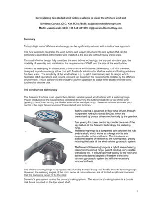
Turbine yawing is governed by four small drivers through
four parallel hydraulic closed circuits, which are
pressurized by pumps driven mechanically by the gearbox.
Fast yawing for power control is possible because of the
key feature of the Seawind technology: the teetering
hinge.
The teetering hinge is a dampened joint between the hub
and the shaft, which works as a hinge with its axis
perpendicular to the shaft axis. This introduces an
additional degree of freedom to the running rotor, greatly
reducing the loads of the wind turbine gyroscopic system.
The Seawind 6 teetering hinge is a hybrid sleeve bearing
elastomeric teetering hinge, patent pending, very reliable
with a long life. It ensures perfect stability to the rotor and
delivers the desired degree of freedom to the wind
turbine’s gyroscopic system but with the necessary
torsional stiffness.
The elastic teetering hinge is equipped with a full stop bumper being less flexible than the teetering hinge.
However, the teetering angles of the rotor, under all circumstances, are of limited amplitudes to ensure
that the bumper is never hit by the rotor.
Seawind’s yaw system is also the primary braking system. The secondary braking system is a double
disk brake mounted on the low speed shaft.
2. 2
In any case, the design of the yaw system (i.e. the controller and the monitoring system) allows under all
circumstances to bring the turbine to a standstill by yawing - even in an emergency - at a yaw rate of 10
deg/s.
The shaft, gearbox, and generator are all
“bedplate mounted”. A very stiff tubular steel
body replaces the bedplate and nacelle cover.
This creates ample space for O&M activities and
the handling of components inside the nacelle.
This tubular steel body is designed to support a
large helideck for twin-engine helicopters.
The electrical system of the Seawind 6 is based
on a squirrel cage generator coupled to a full
power converter. Converter and other electrical
equipment are arranged in the support structure
to allow for passive cooling.
The primary advantages of Seawind 6’s two-bladed teetering hinge technology versus traditional three-
bladed turbines are:
A cost effective life extension of at least 5 years (i.e. from 25 years design life to +30 years) due
to the lower fatigue of the drive train and blades;
Lighter and smaller drive train components, and lighter nacelle, due to lower torque of the drive
train with relatively higher speed (20 rpm of the rotor);
A gearbox without any bending moments at the input low-speed side, and with a well-controlled
output torque at the high-speed end;
A very spacious steel nacelle body for all O&M onboard, yet with a significantly lighter turbine
head compared to three-bladers with same rotor size;
Easy handling of the turbine in harbors during assembly operations (no large, star-shaped rotor).
The support structure type
Seawind’s support structure is designed to allow for complete assembly of the system at a pier. This
method is facilitated by the two-bladed almost mono-dimensional rotor. No large handling area is
required. For shallow waters, the support structure is a piled tetrapod construction made of bolted parts.
For deep waters, the support structure is a spar buoy fabrication also made of bolted parts.
The modality of assembly and installation
Subsequently, the system is towed out to sea with simple tug boats and installed at the site without the
need of any heavy, expensive crane equipment that is required for the industry’s state-of-the-art
procedures today.
Seawind’s complete system is fully assembled at the pier, not at sea, and installed through a simple self-
installing process.
For shallow water the system (i.e. tetrapod support structure and wind turbine on top) is assembled
vertically by a crane at the pier on a semi-submergible barge.
The assembly is completed by arranging inside the legs of the tetrapod piles with the relevant pile driving
devices or suction piles.
3. 3
For deep waters, the spar buoy support structure is assembled by two cranes, horizontally, onto the water
surface at a pier. Following this assembly, the nacelle is mounted on the horizontal spar buoy in the
water, followed by the rotor with the two-blades directed along the spar.
This complete system is towed out to sea with simple tug boats and is installed at the site by ballasting
the bottom section of the spar. The spar is then turned slowly around a horizontal axis close to the sea
surface, like a hinge, through a combination of water ballast, buoyancy, and weight of the system.
The modality of O&M
The Seawind 6 is designed to simplify any inspection, minor or major overhaul, to reduce maintenance
operation times at sea and avoid costly heavy marine equipment.
The criteria adopted are:
- Double access (via sea and via air) directly to the system;
- Ability to repair the components on board;
- Ability to lower the nacelle components onto a supply vessel or barge with simple winches
mounted on the helideck or by the rail inside the nacelle;
- Ability to lift the electrical components inside the support structure to the main door at the service
platform level and from there to lower them on a supply vessel or maintenance barge.
The wind turbine size
The present Seawind 6 (6.2 MW, 126 m diameter) was chosen in order to have initially one wind turbine
suitable for shallow and deep water deployments and to limit the loads of the floating support structure.
For shallow waters, the optimum rotor size is approximately 160 meters, which will add additional
costs/benefits.
In principle, Seawind’s technology can be uprated well beyond
6 MW of installed capacity.
The optimum turbine size, taking into consideration all factors,
which determine the cost of the kWh produced, needs to be
further investigated.
The performance and loads of the Seawind 6 turbine are based
on an extensive functional analysis carried out by the Bladed
simulation program according to IEC 61400-1 Edition 3 and considering the characteristics of Seawind’s
technology. For this purpose, Bladed was equipped with custom made software-plugins simulating the
Seawind 6 turbine controller and hydraulic yaw system.
4. 4
Conclusion
Assembling wind turbines in the offshore environment as if they were on land (i.e. by first installing the
foundation, then the tower, then the nacelle, and then the rotor of three bladed turbine) is wrong because
it is very costly.
Offshore crane or installation vessels preclude cost effective offshore wind energy production. Offshore
wind turbines and relevant support structures need to be considered and designed as one system, not a
lower part (foundation) and upper part (wind turbine).
Two-bladers can be integrated in a self-installing system allowing for complete assembly at the pier. The
complete system can be lowered at the sea site and installation into the sea bed can be done either by
pile driving or drilling or using suction piles, without the need for heavy crane or installation vessels. In
deep waters, installation can be conducted by a simple self-erecting process of the spar-buoy based
system. In this case normal mooring lines are set only to keep the unit in place. These solutions allow for
economic installations of offshore wind turbine systems in all commercially relevant water depths from
10 to 500 meters.
The introduction of a teetering hinge eliminates bending moments in the drive train, reduces fatigue and
ultimate loads, and enables the elimination of the pitch control.
The combination of these innovative assembly/installation methods with the novel two-bladed wind turbine
technology significantly lowers CAPEX and OPEX, while greatly extending the operational time of the
Seawind 6 at sea. As such, the expected result is a CoE close to the actual onshore level.
This wind turbine system is designed exclusively for offshore use. Its higher tip speed and its aesthetics
would make the deployment of such a system onshore problematic. At the same time, the ongoing
deployment of today’s three-bladed wind turbines in the offshore environment, which were initially
designed for onshore usage, is simply not the correct choice.