
Recommended
More Related Content
Similar to RAKESH PPT.pptx
Similar to RAKESH PPT.pptx (20)
Recently uploaded
Recently uploaded (20)
RAKESH PPT.pptx
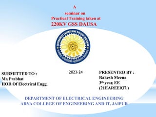
- 1. A seminar on Practical Training taken at 220KV GSS DAUSA PRESENTED BY : Rakesh Meena 3th year, EE (21EAREE037.) DEPARTMENT OF ELECTRICAL ENGINEERING ARYA COLLEGE OF ENGINEERING AND IT, JAIPUR SUBMITTED TO : Mr. Prabhat HOD Of Electrical Engg. 2023-24
- 2. Introduction Definition Of sub-Station Component Of sub-station LightningArrestor Capacitor voltage Transformer PLCC Isolater Current Transformer Circuit Breaker Bus Bar Transformer Protective relay Control room Conclusion
- 3. RVPNL is a company of Rajasthan State Electricity Board(RSEB) established by government of Rajasthan. Aim of RVPNL is to provide reliable transmission service to customers. 220 KV G.S.S., Dausa is a part of RVPNL. .
- 4. FEEDERS OUTGOING FEEDERS 220 K.V. SAW AI MADHOPUR LALSOT ALWAR BASSI -1 (PGCIL) BASSI -2 (PGCIL) SIKRAI MANDAWAR 132KV. BASSI BANDIKUI NAGAL PYARIWAS TOONGA
- 5. SINGLE LINE DIAGRAME 220KV GSS, DAUSA
- 6. Sub-station is a subsidiary station of an electric generation ,transmission and distribution system where voltage is transformed from high to low or low to high voltage using transformers. Electric Power may flow through several sub- station between generated plant and consumer and may be changed in voltage in several steps.
- 7. 1. Primary power lines 2. Ground wire 3. Overhead lines Transformer for measurement of electric voltage 1. Disconnect switch 2. Circuit breaker 3. Current Transformer 4. Lightning arrester 5. Main Transformer 6. Control building 7. Security fence 8. Secondary power lines
- 8. Lightning arrester is a protective device which provides protection against high voltage surges.A lightning arrester has two terminals viz a high voltage terminal and a ground terminal.
- 9. Capacitive voltage transformers are special kind of power transformers using capacitors to step down the voltage. capacitive voltage transformer
- 10. Wave trap A Line trap (high-frequency stopper) is a maintenance-free inductor, mounted inline on high voltageAC transmission power lines to prevent the transmission of high frequency (40 kHz to 1000 kHz) carrier signals of line communication to unwanted destinations.
- 11. PLCC for exchange of data and transfer of messages between substations, voice communication is necessary. For this purpose high frequency carrier current is transmitted over same transmission line on which power is transmitted. Hence this communication is called as power line carrier communication.
- 12. maintenance. It operates when there is no load. It is also used It isolates to change the devices bus bar line from live from main to line when reserve or there is a vise versa. 220 KV ISOLATOR
- 13. C.T. is used to measure high value of current. C.T.`s secondary is connected to relay to protect the system against Overcurrent. Current T ransformer
- 14. Circuit breaker two popular breakers used Today, most Circuit are in substation which are: V acuum Circuit breaker & SF6 Circuit breaker. Oil and Air Circuit was earlier blast breaker used in decades.
- 15. Bus Bars are common electrical component through which a large no. of feeders operating at same voltage have to be connected.
- 16. The transformer is a static apparatus, which receives power/energy at it, one circuit and transmits it to other circuit without changing the frequency and power.
- 17. 1. Primary and secondary coils (circuit) or windings. 2. Core 3. Main Tank 4. Conservator 5. Breather 6. Radiator 7. Buchholz relay 8. Bushings (HT & LT) (Primary or secondary) 9. Cooling fans 10. Tap changer (on load and off load) 11. NGR (Neutral Grounding Resistance) to minimize the earth fault current
- 18. To step-up or step-down the voltage and transfer power from one a.c. voltage to another a.c. voltage at the same frequency.
- 19. The capacitor bank provides reactive power at grid sub-station.the voltage problem frequently reduce so of circulation of reactive power.
- 20. Aprotective relay is a device that detects the fault and initiates the operation of the circuit breaker to isolator the defective element from the rest of the system.
- 21.