More Related Content
Similar to Workbenchwriteup
Similar to Workbenchwriteup (20)
Workbenchwriteup
- 1. May 9, 2006
Page 1 of 103
© 2006 –For Free Distribution –http://www3.telus.net/steve_n_shelly
Building a Cabinet Maker’s Workbench
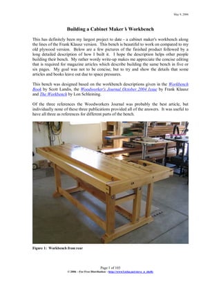
This has definitely been my largest project to date - a cabinet maker's workbench along
the lines of the Frank Klausz version. This bench is beautiful to work on compared to my
old plywood version. Below are a few pictures of the finished product followed by a
long detailed description of how I built it. I hope the description helps other people
building their bench. My rather wordy write-up makes me appreciate the concise editing
that is required for magazine articles which describe building the same bench in five or
six pages. My goal was not to be concise, but to try and show the details that some
articles and books leave out due to space pressures.
This bench was designed based on the workbench descriptions given in the Workbench
Book by Scott Landis, the Woodworker's Journal October 2004 Issue by Frank Klausz
and The Workbench by Lon Schleining.
Of the three references the Woodworkers Journal was probably the best article, but
individually none of these three publications provided all of the answers. It was useful to
have all three as references for different parts of the bench.
Figure 1: Workbench from rear
- 2. Page 2 of 103
© 2006 –For Free Distribution –http://www3.telus.net/steve_n_shelly
Figure 2: Workbench from front
Figure 3: Workbench from front
- 3. Page 3 of 103
© 2006 –For Free Distribution –http://www3.telus.net/steve_n_shelly
Figure 4: Front of shoulder vice
Figure 5: Shoulder vice end-cap
- 4. Page 4 of 103
© 2006 –For Free Distribution –http://www3.telus.net/steve_n_shelly
Figure 6: Tail vice front view
Figure 7: Tail vice –saved the best figure for the front-most board!
- 5. Page 5 of 103
© 2006 –For Free Distribution –http://www3.telus.net/steve_n_shelly
Figure 8: Tail vice dovetail and handle
Figure 9: Tail vice end-cap and rear-view
- 6. Page 6 of 103
© 2006 –For Free Distribution –http://www3.telus.net/steve_n_shelly
Figure 10: Tool tray dovetails
- 7. Page 7 of 103
© 2006 –For Free Distribution –http://www3.telus.net/steve_n_shelly
Figure 11: Cherry crotch veneered tool tray ramp
- 8. Page 8 of 103
© 2006 –For Free Distribution –http://www3.telus.net/steve_n_shelly
1 Sourcing and Rough Cutting the Wood
The first difficulty in building a bench is finding the materials. For over a year I was
keeping my eye out for some appropriate wood. One day I walked into my local
hardwood dealer and they were just putting out a new shipment of 10' long by 6 to 12"
wide 8/4 maple. The wood was lovely with almost no knots and a fair bit of nice white
sap wood. I snapped up 180 bf to build the bench with. I used almost the entire amount,
although there are a number of useable off-cuts left over. Below is an estimate showing
the amount of wood required for each piece (using approximate dimensions), along with
a cost estimate. Note –I know a lot of people out there can buy gold-plated maple at
$1.00 per bf, but you don’t live in Western Canada. It costs a lot more out here. I did
have a line on some 4/4 maple at $1/bf, but it was only 6’long and would have been two
to three times as much work dimensioning all those little boards. Prices in the following
table are in 2005 Canadian dollars. The US to Canadian exchange rate was around 1.2 to
1 at the time.
- 9. Page 9 of 103
© 2006 –For Free Distribution –http://www3.telus.net/steve_n_shelly
Wood and Cost Estimate
Dimensions in Inches
L W D
BF $/BF $
Top - 3" thick section (8/4) 89.5 16.5 3 30.8 5.95 183
Top - 4" thick doghole strip (8/4) 93 5.4 4 13.9 5.95 83
End-caps & vice arm (8/4) 94.1 3.25 4 8.5 5.95 51
Shoulder vice spacer (8/4) 8.5 6.25 2.75 1.0 5.95 6
Tool tray back board (5/4) 95.0 1 4 2.6 4.95 13
Base #1 - top and bottom arms (8/4) 72.5 3 4 6.0 5.95 36
Bases #1 & #2 - cross brace (8/4) 32.5 1.5 2.5 0.8 5.95 5
Base #1 - vice leg (8/4) 30.5 2.25 2 1.0 5.95 6
Bases #1 & #2 - main legs (8/4) 122.5 3.5 2.75 8.2 5.95 49
Base #2 - top and bottom arms (8/4) 54.5 3 4 4.5 5.95 27
Stretchers (8/4) 256 1.75 4 12.4 5.95 74
Spacers under bench (5/4) 46 3 1 1.0 4.95 5
Off-cuts & waste (8/4) 89.2 5.95 531
Tool tray bottom (1/2”maple ply) 10
Veneer for tool tray ramps 5
1 gallon white glue 15
Scandinavian vice screw and handle 97
Small welded tail vice and handle 192
Wooden bench-dogs 42
Lee valley bench bolts 60
Lee valley bed bolts 15
Leveller feet 8
5/8" threaded rod 5
Stainless #14 screws 13
1-1/8" dowel for new handle 5
Insert screws for new handle 3
Finishing supplies 70
Sub-total 1,587
GST (sales tax @ 7%) 111
Grand Total $ 1,698
Total board feet 180
- 10. Page 10 of 103
© 2006 –For Free Distribution –http://www3.telus.net/steve_n_shelly
Figure 12: Lumber Pile - Maple for Bench in Foreground –January 27, 2005
I developed a cutting strategy to maximize the use of the wood. I planned a bench about
8' long so that I could cut the nice 8' off the boards for use in the top, and use the
remaining 2' of each board for building the base and other non-visible bits of the bench.
This worked out very well, and of the 180 bf, I only ended up with about three garbage
cans full of off-cuts that were destined for the fire pit plus there are a lot of useable off-
cuts now piled up in my basement. Half of one board was so full of hidden shakes that I
could not use that board.
- 11. Page 11 of 103
© 2006 –For Free Distribution –http://www3.telus.net/steve_n_shelly
Figure 13: Enjoying the off-cuts –maple burns nicely, cherry burns with a beautiful blue flame!
Now is the time to develop a fairly detailed design. Planning ahead allows you to rough
cut your wood in a non-wasteful manner. I drew up designs for the bases and the bench
top, leaving out minor details. At this time I did not have my vice hardware - although I
knew general dimensions - but it would have been better to have had the hardware in
hand and to have done the detail design of the vices at this time! With a plan in hand, I
laid out the boards for rough cutting:
A note on the drawings in this write-up: although I built this bench from these drawings
and have tried to correct any mistakes, undoubtedly there will be mistakes and omissions.
Sorry - you get what you pay for. Having said that, each bench is slightly different due to
the dimensions of the wood you start with and the particular hardware you choose, so I
highly recommend that you make a detailed set of plans for yourself.
- 12. Page 12 of 103
© 2006 –For Free Distribution –http://www3.telus.net/steve_n_shelly
Figure 14: Developing the cutting plan (note the nice tidy basement!) –March 03, 2005
Now the dirty work began. I selected the best, whitest pieces of wood for use as the top.
I ripped the wide boards into fifteen 4 to 5" wide strips, and crosscut the remaining bits
into appropriate lengths for the legs. I did this on my 2 hp General International
contractor's saw. It had enough gumption to do the job - with the occasional breaker trip
- but a band saw would have been a much better choice. About half-way through this
project I bought a great used band saw and realized how much easier ripping these large
boards would have been if I had used a band saw instead of a table saw.
- 13. Page 13 of 103
© 2006 –For Free Distribution –http://www3.telus.net/steve_n_shelly
Figure 15: Ripping the boards (April 6, 2005)
Some of the boards wanted to warp when cutting and pinched the blade. Make sure you
use a splitter on your table saw when doing this work! I found that crosscutting the long
boards was best done using a hand-held circular saw.
- 14. Page 14 of 103
© 2006 –For Free Distribution –http://www3.telus.net/steve_n_shelly
Figure 16: Cross-cutting the boards –April 6, 2005
This is when I realized how much room I would need to store all the pieces. For most of
the year it took me to build this bench, my two car garage was 80% taken over by this
project.
- 15. Page 15 of 103
© 2006 –For Free Distribution –http://www3.telus.net/steve_n_shelly
Figure 17: Boards rough-cut April 06, 2005
2 Building the Bases
Next I turned my attention to building the bases. Every piece except for the cross-braces
was made up by laminating two 8/4 boards together. I jointed all of my stock using hand-
planes, so this was a heck of a lot of hand planing. If I was to build this bench again, I
might take the trouble to get hold of 12/4 stock. This would have significantly cut the
amount of work required. Using the 8/4 stock I was forced to dimension two pieces,
laminate them together, then dimension the finished piece. This was lots of duplicate
work. Some of the boards also seemed VERY abrasive, to the point where my plane
would be dull after 30 to 40 seconds of planing. Other boards I could plane all day
without sharpening. The difficult boards were VERY frustrating.
- 16. Page 16 of 103
© 2006 –For Free Distribution –http://www3.telus.net/steve_n_shelly
Figure 18: General Dimensions of Shoulder-Vice-End Base
The following drawing shows the shoulder-vice-end base including the bench top. The
front end of the bench top was 4”thick, while the remainder of the bench top was 3”
thick. This makes the top of this bench 34-5/8”off the ground –slightly higher than
recommended by some, but it feels comfortable for me (I’m 5’-10”tall). A 1”high
spacer block, not shown in the drawing, fills the gap between the top of the base and the
3”thick section of the bench top.
- 17. Page 17 of 103
© 2006 –For Free Distribution –http://www3.telus.net/steve_n_shelly
Figure 19: General Dimensions, including bench top thickness (front of bench is to the right)
- 18. Page 18 of 103
© 2006 –For Free Distribution –http://www3.telus.net/steve_n_shelly
Figure 20: General Dimensions of Tail-Vice-End Base
Here's a picture of the dimensioned stock...note I don't store pieces like shown in this
picture. I always stack pieces with stickers between them to allow equal air circulation
around every board. I find this helps to prevent warping.
- 19. Page 19 of 103
© 2006 –For Free Distribution –http://www3.telus.net/steve_n_shelly
Figure 21: Dimensioned stock for bases –March 19, 2005
After dimensioning the wood, I joined the pieces using through wedged mortise and
tenons. After laying out the joinery I drilled a single pilot hole in the middle of the
mortise. This gave the chips somewhere to go and let me drive the chisel more deeply
than if there were no pilot hole. The perpendicular pencil lines drawn on the mortise
were a crutch to keep my chisel square to the cut.
- 20. Page 20 of 103
© 2006 –For Free Distribution –http://www3.telus.net/steve_n_shelly
Figure 22: Chopping Mortises - drilling pilot hole
Second, I chopped towards one end, stopping just short of the end. I cleaned up the last 2
or 3 mm of the mortise after I had hogged out most of the waste.
- 21. Page 21 of 103
© 2006 –For Free Distribution –http://www3.telus.net/steve_n_shelly
Figure 23: Chopping mortises –half done
Next I chop to the other end. I had to make several passes to get a mortise 2-3" deep.
Once I was at the final depth, I chopped the ends of the mortise square and double
checked to verify that the sides and ends were parallel and square:
- 22. Page 22 of 103
© 2006 –For Free Distribution –http://www3.telus.net/steve_n_shelly
Figure 24: Chopping mortises - checking to see if ends and sides are square
This method went pretty quick. I think the pilot hole makes chopping mortises a lot
easier, and there are lots of mortises in a workbench base:
- 23. Page 23 of 103
© 2006 –For Free Distribution –http://www3.telus.net/steve_n_shelly
Figure 25: Chopping mortises –done!
The tenons were roughed out on the table saw using a tenon jig. They were too large to
cut with my tenon handsaw. As a matter of fact, they were too big for my table saw. I
finished off cutting the tenons using a panel saw, and then fine tuned the fit with a
shoulder plane. This would have been a perfect job for a band saw if I had had one at the
time.
- 24. Page 24 of 103
© 2006 –For Free Distribution –http://www3.telus.net/steve_n_shelly
Figure 26: Finishing off the tenons with a handsaw
I used wedged mortises on my base, but I don't think they're necessary. With a 4"x3"
tenon there is a huge glue surface. In the photo below I haven't cut the space for the
wedge into the tenon, but the through-mortise is complete. I cut the angled ends of the
mortise using a chisel and a 3 degree guide block. The wedges were cut out of a 1/2"
thick cherry board at a 3 degree angle using a taper jig on the tablesaw.
- 25. Page 25 of 103
© 2006 –For Free Distribution –http://www3.telus.net/steve_n_shelly
Figure 27: Through tenon - showing allowance in mortise for wedges
Here's a picture of the assembled (but not glued) bases:
Figure 28: Bases assembled –April 18, 2005
I wanted to incorporate adjustable levelling feet into the bench. Finding appropriate feet
was difficult, so I ended up with typical appliance feet; rated at something like 350 lbs
each. I used an idea promoted by Michael Fortune in The Workbench Book, and made
- 26. Page 26 of 103
© 2006 –For Free Distribution –http://www3.telus.net/steve_n_shelly
the levellers adjustable from the top of the bench. I also countersunk the feet into the
bench because I wanted a low profile look, and I didn't want the bench to be any higher
than I had already designed into the bases (ahem… another reason to plan ahead). After
installing the levellers, I cut the threaded rods down so they would be approximately
flush with the top of the sled feet.
The following is a drawing detailing installation of the levellers. My garage floor is
gently sloped, so I allowed for this slope in the drawing. These holes were drilled
freehand but, as with the band saw, I acquired a used drill press part way through this
bench project, and I now realize how much easier things would have been if I had the
proper tools at the start of the project.
Figure 29: Detail of leveller installation
- 27. Page 27 of 103
© 2006 –For Free Distribution –http://www3.telus.net/steve_n_shelly
Figure 30: Holes drilled in underside of foot for leveller
- 28. Page 28 of 103
© 2006 –For Free Distribution –http://www3.telus.net/steve_n_shelly
Figure 31: Leveller foot underside –June 18, 2005
Before gluing up the bases, I cut the profiles on the ends of the sled feet. I did this on the
band saw, cleaned up the saw marks using a spokeshave, and then finished up by sanding
the end-grain to 400 grit - smooth as a baby's bottom.
- 29. Page 29 of 103
© 2006 –For Free Distribution –http://www3.telus.net/steve_n_shelly
Figure 32: Final shaping of ends of sled feet
After profiling the ends, I trimmed the screw on the leveller feet to be flush with the foot
profile. I cut a slot into the top of the screw so that it could be adjusted with a
screwdriver. I cut the slot with an angle grinder equipped with a cut-off wheel, but a
hacksaw would have worked as well.
The last step in completing the sled feed was to cut the recess on the underside of the sled
foot. I cut this out on the bandsaw and removed the saw marks with a spokeshave and
scrapers.
- 30. Page 30 of 103
© 2006 –For Free Distribution –http://www3.telus.net/steve_n_shelly
Figure 33: Completed foot showing leveller adjustment screw
With the feet complete, it was time to glue up the bases. The shoulder-vice-end base was
a bit tricky to glue up because all three vertical legs have to line up perfectly to fit into
their mortises. This is a bit like trying to juggle cats, meanwhile your glue is skinning
over. I ended up having to pound mine together, resulting in breaking my cheap mallet.
This was a good excuse to go to Lee Valley and buy a good mallet. Luckily that metal
cylinder didn’t go flying across the room when I was pounding the base together.
- 31. Page 31 of 103
© 2006 –For Free Distribution –http://www3.telus.net/steve_n_shelly
Figure 34: Broken mallet - doesn't pay to buy cheap (or at least you shouldn’t pound on a
cheap mallet too hard).
3 Stretchers
With the bases assembled, the stretchers were the next pieces to be made. I selected the
worst boards for the stretchers –thinking they were the least important boards in the
bench –but once the finish was applied, these “worst”boards turned out to have some of
the nicest figure. The boards had several splits and checks in them but this didn’t hurt
their use as stretchers. I filled the splits with epoxy beforehand just to make sure they
didn’t spread.
Below are drawings of the stretchers. Note that the tenon on the upper stretcher is offset
downwards to move the accompanying mortise in the bench leg further away from the
end of the leg. The tenon on the lower stretcher is offset in the opposite direction.
- 32. Page 32 of 103
© 2006 –For Free Distribution –http://www3.telus.net/steve_n_shelly
Figure 35: Stretcher dimensions
The first thing I realized when trying to dimension the stretcher boards was that my
current bench was inadequate. The bench was not flat enough along its length to allow
me to accurately dimension boards as long as these stretchers. So, I spent a day levelling
my plywood bench using a floor jack and a billion shims. A piece of plywood acted as
an eight-foot long straight edge.
Figure 36: Levelling my old bench –April 18, 2005
- 33. Page 33 of 103
© 2006 –For Free Distribution –http://www3.telus.net/steve_n_shelly
Once the workbench was levelled, dimensioning and cutting the joinery on the stretchers
was easy. The stretchers are tenonned into the bases, but the tenons are not glued so that
the base can be disassembled if I ever have to move this beast. I used Lee Valley’s bench
bolts to hold the stretchers in place. They are a bit expensive, but work great and have a
nice clean appearance.
Figure 37: Lee Valley Bench Bolts (picture from Lee Valley’s web-site
http://www.leevalley.com)
Installing the bolts was another chore that would have been much easier with a drill press.
Nevertheless, with careful hand-drilling, the installation was almost perfect. Following
are some sketches of the bench bolt installations. As a general comment on all of the
sketches, some of the silly dimensions, such as drilling a 1-33/64”hole, are not what I
actually did. The hole is drawn at 1-33/64”because I eyeballed the dimension on the
sketch. When constructing the bench, I took a washer, compared the diameter to my
available stock of drill bits, and selected the next larger size bit. Instead of drilling a hole
21/32”deep, I drilled a hole around 5/8”deep, then checked to see if the hole was deep
enough so that the bolt head was completely recessed, and so on.
- 34. Page 34 of 103
© 2006 –For Free Distribution –http://www3.telus.net/steve_n_shelly
Figure 38: Upper stretcher tenon location
- 35. Page 35 of 103
© 2006 –For Free Distribution –http://www3.telus.net/steve_n_shelly
Figure 39: Lower stretcher tenon location and bench bolt installation details
Once the stretchers were installed and tightened up, the base was almost complete! The
last step was to ensure that the tops of the bases were flat and not twisted relative to each
other. These steps were easy to do with a hand-plane and some winding sticks. I noticed
that with a non-flat floor, it is easy to introduce twist into the base when relocating it.
The floor levellers should be used to re-level and untwist the base every time the base is
moved.
Time for a rest - working on a bench is exhausting:
- 36. Page 36 of 103
© 2006 –For Free Distribution –http://www3.telus.net/steve_n_shelly
Figure 40: Exhausted after a good day working on the bench
4 Assembling the Benchtop
After a good rest, the real work began –dimensioning the boards for the top. As I said, I
face and edge jointed every one of these boards by hand. Luckily - breaking my rule of
not realizing how much easier some things are if you have the right tool until after the job
is done - I had already bought a thickness planer. There was no way I was going to
thickness this many maple boards by hand. Jointing the boards by hand was enough
work. Each one of the boards was perfectly square and very close to perfectly straight
before I started the glue-up.
First I laid out the boards with two criteria, in order of importance:
1. First, the grain direction for all boards must be the same! This makes the job of
flattening the top much easier at a later date. In addition I wanted to plane from
right to left, so the grain direction of all boards was rising right to left.
2. Second, I ordered the boards for a pleasing appearance, with the whitest wood
upwards and flaws downwards.
- 37. Page 37 of 103
© 2006 –For Free Distribution –http://www3.telus.net/steve_n_shelly
3. One board was narrow enough that it ended up being less than 3”tall. I put this
board on the very back of the benchtop, and cut that board to 2-1/2”tall. This
resulted in my tool tray only being 2-1/2”deep instead of the 3”that I wanted, but
I figured that if 2-1/2” was enough for Frank Klausz, it was probably good
enough for me.
Below is a picture of the boards laid out ready for glue-up:
Figure 41: Benchtop boards laid out for best grain direction
My glue-up strategy was to glue one board at a time. I know some people can glue up all
fifteen boards in one shot, but not me. My plan was to glue the first two boards together,
dimension that piece so that it became a nice straight reference, then glue the next piece
on and so on. Once I had four boards glued together and dimensioned nice and straight, I
had a very strong reference beam which I could use when clamping and gluing future
pieces in place.
- 38. Page 38 of 103
© 2006 –For Free Distribution –http://www3.telus.net/steve_n_shelly
Figure 42: Gluing up the first course of four boards –May 29, 2005
This strategy worked very well, and the resulting glue up was very straight, non-twisted,
and required minimal clean-up work. I actually glued up the top into five sections. Each
section was three to four boards thick resulting in an assembly 8 to 10”wide. Each
section was jointed, and then run through the thickness planer so that each section was of
equal thickness, then the sections were glued together. Four of the five sections made up
the 3”thick part of the bench. The fifth section (of four boards) was the front part of the
bench which houses the doghole strip, and was four inches thick.
I drilled the hole for the shoulder vice threaded rod though each section of the benchtop
before gluing the sections together.
Below is a picture of two courses of the benchtop after glue-up:
- 39. Page 39 of 103
© 2006 –For Free Distribution –http://www3.telus.net/steve_n_shelly
Figure 43: Two courses glued up and waiting –June 12, 2005
Following is a picture of the entire 3”thick section of the bench being glued up. Note
that I had trimmed the ends of the sections to be approximately square before the glue-up.
It’s at this point that you realize how heavy this bench will be.
- 40. Page 40 of 103
© 2006 –For Free Distribution –http://www3.telus.net/steve_n_shelly
Figure 44: 3" thick part of benchtop being glued up –June 19, 2005
Three of the four 4”tall boards which form the front part of the bench were glued up, but
the fourth board was left loose until the dogholes had been machined.
5 Machining the Dogholes and Planing Stop
Forming the dogholes was one of the more enjoyable jobs on this bench even though I
typically don’t like using routers. When buying my bench hardware from Lie-Nielsen I
also bought two wooden bench dogs. I used the benchdogs as guides for building a
router template. The dogholes are installed at 88 degrees to the benchtop. I won’t
remind you to angle the dogholes in the correct direction – the reference books and
magazines do a good enough job of that!
The dogholes were carefully spaced with a number of criteria in mind:
1. A doghole should not be located over one of the bases to avoid interference.
2. The first doghole should be located close to the tail vice face (I used a 1”gap
between the tail vice face and the first doghole). Locating the first doghole close
to the tail vice face allows short pieces (as short as 2”) to be held in the tail vice.
- 41. Page 41 of 103
© 2006 –For Free Distribution –http://www3.telus.net/steve_n_shelly
3. Spacing of the remaining dogholes should be fairly close together. I aimed for a
4”spacing, but ended up with a 5”spacing to meet all of these criteria.
4. Dogholes, except for the last one, should be equally spaced for pleasing visual
appearance. My doghole spacing was different on the bench body than it was on
the tail vice (3-3/64”spacing)
5. Dogholes in the tail vice should not interfere with installation of the metal tail
vice hardware. The tail vice is screwed into the doghole strip, so I located the
dogholes so that there was no interference with these screws.
6. Frank Klausz locates the last doghole directly up against the end-cap. I didn’t like
that, so I offset my last doghole about 1”from the end-cap. I don’t know which
way is better or if it matters at all.
Below is a sketch of the top showing the benchtop, the bases, and the doghole spacing.
Figure 45: Benchtop showing doghole spacing (bench base is shown in red below the benchtop)
I used a ½”straight bit in my router to cut the dogholes. A guide bushing ran along the
inside of the router template. The template was clamped onto the doghole strip.
The top of the template was ¼”hardboard. Two pine guides (jointed 2x4s) were screwed
to the underside of the template, sandwiching the doghole strip between them.
- 42. Page 42 of 103
© 2006 –For Free Distribution –http://www3.telus.net/steve_n_shelly
Figure 46: Benchdog and benchdog router template –top view
- 43. Page 43 of 103
© 2006 –For Free Distribution –http://www3.telus.net/steve_n_shelly
Figure 47: Benchdog template clamped in place –underside view showing one of the 2x4 guides
- 44. Page 44 of 103
© 2006 –For Free Distribution –http://www3.telus.net/steve_n_shelly
Figure 48: Routing benchdog holes –September 04, 2005
- 45. Page 45 of 103
© 2006 –For Free Distribution –http://www3.telus.net/steve_n_shelly
Figure 49: Benchdog in hole
Once all of the dogholes are cut, the last benchtop strip can be glued onto the doghole
strip, covering up the dogholes. Note that I selected the nicest looking board to be the
front of my bench:
- 46. Page 46 of 103
© 2006 –For Free Distribution –http://www3.telus.net/steve_n_shelly
Figure 50: View of dogholes before cover strip glued on
Finally, the doghole strip can be glued to the rest of the benchtop and filler strips can be
added to the underside of the bench. Don’t forget to drill the hole for the shoulder vice
threaded road, and to cut the slot for the planing stop before gluing the doghole strip onto
the rest of the bench. It is also much easier to square up the tail-vice end of the doghole
strip now before it is glued to the rest of the bench.
Following is a picture of the planing stop. Like the dogholes, the planing stop was
installed at an 88 degree angle to the benchtop. I wasn’t sure I wanted this feature and at
first I had trouble figuring out what this thing was when reading through the various
books. However, I find it is very useful and I highly recommend installing this feature on
your bench. I cut the slot on my table saw using the mitre gauge set at a 2° angle. It’s a
bit hairy manoeuvring a piece of wood this large on a standard sized table especially
when a screw-up might wreck a lot of hard work.
- 47. Page 47 of 103
© 2006 –For Free Distribution –http://www3.telus.net/steve_n_shelly
Figure 51: Planing stop
- 48. Page 48 of 103
© 2006 –For Free Distribution –http://www3.telus.net/steve_n_shelly
Figure 52: Benchtop before doghole strip glued in place (view from rear of bench) –doghole strip is
4”thick, remainder of benchtop is 3”thick.
- 49. Page 49 of 103
© 2006 –For Free Distribution –http://www3.telus.net/steve_n_shelly
Figure 53: Doghole strip glue to main body of bench place. Filler strips under the 3”thick section of
the bench are in place. Hole for shoulder vice threaded rod is visible at back of benchtop. November
27, 2005
- 50. Page 50 of 103
© 2006 –For Free Distribution –http://www3.telus.net/steve_n_shelly
6 Finishing off the Top –Filler Strip
The filler strips under the bench rest on the top of the bases. To accommodate expansion
and contraction of the benchtop, only the front of the filler strip is firmly screwed to the
benchtop. The back end of the filler strip is loosely screwed in place with room for
expansion. A 1”diameter hole is drilled through the filler strip, and a matching hole is
drilled in the base to accommodate a bullet dowel which connects the benchtop to the
bases.
Figure 54: View of underside filler strip
- 51. Page 51 of 103
© 2006 –For Free Distribution –http://www3.telus.net/steve_n_shelly
Figure 55: Underside of bench showing filler strip and bullet dowel
At this point, you now have a working bench. I took the time to roughly flatten the bench
so that things were close to flat and the bench could be used to dimension stock. At this
point I also squared off the ends of the bench by clamping a straight edge across the
benchtop and trimmed the ends of the bench with a router and a 3”long ½”diameter
router bit, followed by fine tuning with a handplane.
- 52. Page 52 of 103
© 2006 –For Free Distribution –http://www3.telus.net/steve_n_shelly
7 Attaching the End-Caps
Prior to attaching the end-caps, I squared off the ends of the bench by clamping a straight
edge across the table and running a router with a straight bit along the straight edge. I
touched up the ends using a hand-plane to get perfectly square and perpendicular ends.
Precision now pays off later.
I had rough dimensioned the end-cap stock to 3-1/4”wide by 4”tall at the same time as I
built the bases. The pieces warped a bit during storage, so my end-caps came in slightly
under 3-1/4” wide once everything was straightened out. After the end-caps were
dimensioned, I cut slots into both the end-caps and the ends of the bench to accommodate
plywood splines. I used ~5/8”Baltic birch plywood as the spline material.
I cut the slots using a router with an edge guide. I always referenced the edge guide off
the top surfaces of the bench and the end-caps so that things aligned perfectly. The slots
were cut in the centre of the 3”section of the bench.
Figure 56: Spline groove formed in bench end –February 04, 2006
- 53. Page 53 of 103
© 2006 –For Free Distribution –http://www3.telus.net/steve_n_shelly
The end-caps are held in place by gluing the front 4-6”of the splines (allowing the
benchtop to expand/contract to the rear of the bench). There is also a fixed bolt near the
front of the end-cap and a bolt in a slotted hole near the rear of the end-cap.
I actually cut the slots very slightly undersize and then used a hand-plane to take shavings
off the plywood splines until the splines were a tight fit into the slots. You don’t want
any play in the splines or else your end-caps can move up and down. I found that my
first set of splines, which pressed into the grooves easily with hand pressure, allowed too
much slop in the end-cap attachment. I made a second set of splines that I had to tap
lightly into the grooves with a mallet, and these were much more acceptable. Don’t make
them too tight, however, or else when you apply glue to the splines and the splines swell
a bit, you won’t be able to get the splines into the grooves. A shaving or two makes all
the difference between too loose and too tight.
- 54. Page 54 of 103
© 2006 –For Free Distribution –http://www3.telus.net/steve_n_shelly
Figure 57: Shoulder vice end end-cap dimensions (end-cap is 3-1/8”wide by 4”tall)
- 55. Page 55 of 103
© 2006 –For Free Distribution –http://www3.telus.net/steve_n_shelly
Figure 58: Tail vice end end-cap dimensions (end-cap is 3-5/16”wide by 4”tall)
- 56. Page 56 of 103
© 2006 –For Free Distribution –http://www3.telus.net/steve_n_shelly
Figure 59: End-caps in place. Benchtop is getting very heavy. I had to turn the benchtop 180°.
With only one person, it was a difficult task.
- 57. Page 57 of 103
© 2006 –For Free Distribution –http://www3.telus.net/steve_n_shelly
Figure 60: Shoulder vice end end-cap showing bed bolt locations. Bolt at rear of bench (to left) has a
slotted hole to allow for bench expansion. Can you see the error in this picture? The yellow smudge
to the left of the slotted bolt was an oops where I drilled the bolt hole in the wrong location. I
plugged the hole, but it is slightly visible.
Note: Do not glue the end-caps in place until the shoulder vice and tool tray back-board
have been completed.
8 Assembling the Shoulder Vice
Now that the end-caps were in place, it was time to assemble the shoulder vice. This was
where the fun really began and I felt that I was doing some fine woodworking instead of
heavy timber framing.
The shoulder vice uses a single large dovetail to connect the vice arm to the end-cap. I
laid out this dovetail with 5/8”thick half-pins at the top and bottom of the joint. For
hardwood I would normally use a 1:7 ratio for the dovetail, but I found that on the large
joints such as are used on this workbench, a lower angle looked better. In the end I just
eyeballed the angle and used a proportion that was visually pleasing.
- 58. Page 58 of 103
© 2006 –For Free Distribution –http://www3.telus.net/steve_n_shelly
I made the shoulder cuts first on the tablesaw, and then cut the dovetail on the bandsaw.
This is a large piece of wood and I felt it was too large for me to do a good job with a
handsaw. I used a taper jig to ensure that the dovetail sides were nice and straight.
Figure 61: Cutting the shoulder vice dovetail –February 24, 2006
Once the tail was cut, I transferred the tail onto the pin-board. Because of the size of the
pieces this isn’t as easy as dovetailing a delicate drawer together. Since I had gone to
great lengths to ensure that the end of my bench was nice and square, I ended up
clamping the pieces to my bench at 90 degrees to each other, and transferring the
markings. This worked pretty well. One shoulder was off a bit, but that was due to my
over-exuberance with a chisel and laziness not fixing it.
- 59. Page 59 of 103
© 2006 –For Free Distribution –http://www3.telus.net/steve_n_shelly
Figure 62: Transferring dovetail markings onto pin board
I also cut the pins using the bandsaw. This was a bit trickier than cutting the tails because
I had to exactly match the angle of the pin board to match the angle of the tails. To cut
this angle, I bevelled a board to match the dovetail angle. I used two-sided tape to stick
the pin board onto the bevelled board. Note that the resulting cut in the following picture
was exactly vertical. The pin-board ran along the bandsaw fence. This set-up worked
well and even though it was a bit finicky to get right, the whole process of cutting the pin
probably took less than an hour.
- 60. Page 60 of 103
© 2006 –For Free Distribution –http://www3.telus.net/steve_n_shelly
Figure 63: Cutting the shoulder vice pin-board on the bandsaw using an angled guide. Inside cuts
were practice cuts. Outside cuts were cut very close to the line on bandsaw, then were cleaned up
with a #60-1/2 rabbet plane.
Figure 64: Assembled shoulder vice dovetail before glue-up
- 61. Page 61 of 103
© 2006 –For Free Distribution –http://www3.telus.net/steve_n_shelly
After finishing the joinery on the dovetail, I completed the shoulder vice by drilling the
hole for the shoulder vice threaded rod, profiling the end of the shoulder vice arm,
making the spacer block, and installing the shoulder vice hardware.
Figure 65: Exploded view of the shoulder vice
- 62. Page 62 of 103
© 2006 –For Free Distribution –http://www3.telus.net/steve_n_shelly
Figure 66: Shoulder vice drawing
The shoulder vice spacer block (shown above) must fit tightly between the bench and the
shoulder vice arm. My block was 8-3/4”wide by 7-5/8”long by 2-3/4”thick, made up
by face laminating two 8/4 boards. The block has a hole drilled through it through which
the threaded rod passes and grooves are milled into three sides of the spacer block for
splines.
The thickness of the spacer block determines how much room is left between the spacer
block and the top of the base. An arm off of the shoulder vice jaw rides along the top of
the base, and in my case the height of the arm was just less than 1-1/4”. This can be seen
in the following pictures.
The spacer block grain orientation is important to allow for expansion and contraction.
The grain should be aligned with the grain of the end-caps, as shown in the above picture.
Someone tried to convince me that this arrangement is necessary because it resists
compression better, but I believe the true reason for this arrangement is that it best
accommodates wood movement. When gluing the assembly together, I completely glued
- 63. Page 63 of 103
© 2006 –For Free Distribution –http://www3.telus.net/steve_n_shelly
the spline between the end-cap and the spacer block, but only glued the first four to six
inches of the cross-grain splines nearest to the end-cap.
Figure 67: Underside of shoulder vice showing vice jaw and arm riding under the spacer block.
Spacer block is allowed to expand/contract to the right side of the picture. Splines on left side of
spacer block are glued.
- 64. Page 64 of 103
© 2006 –For Free Distribution –http://www3.telus.net/steve_n_shelly
Figure 68: Side view of shoulder vice showing arm riding on top of base
Note: Do not glue up the shoulder vice assembly until you have cut the joinery for the
tool-tray backboard into the end-caps.
As a finishing touch and to add a bit of personality to the bench, I carved my name and
the year of completion into the vice arm (it would have been too complicated to
carve...“thought about building in 2003, bought wood in 2004, started construction in
2005, finished construction in 2006”). Note that I did the carving after the tail vice was
completed so that I could use the tail vice to hold the work.
- 65. Page 65 of 103
© 2006 –For Free Distribution –http://www3.telus.net/steve_n_shelly
Figure 69: Transferring the lettering to the wood using carbon paper –practice piece in basswood is
visible above the vice arm.
- 66. Page 66 of 103
© 2006 –For Free Distribution –http://www3.telus.net/steve_n_shelly
Figure 70: Lettering laid out
The problem I found with carving lettering this size was that my gouge profiles didn't fit
the curves very well, so I had to chase some of the lines using a knife and other curves I
had to do a sliding cut.
What I found really helped was using a gouge with a fingernail profile. This is against
most of the advice you read about keeping the gouge edge square, but with a fingernail
profile you can adjust the angle of attack to match the curve you are trying to carve.
I found with these 1" high letters, a 20 mm #5 fishtail gouge (with square ends), a #3
Warren fishtail gouge with a fingernail profile, and a Moor chip-carving knife were the
most useful tools. For some of the letters, such as the "6" in 2006, some of my larger
gouges were useful but, as you’ll see, the “6”is the only letter that I’m not really happy
with –I was using a large gouge and caught an edge resulting in a wider cut than I
wanted.
The font that I ended up using was Garamond 72 point photocopied at 150%.
One thing I had to watch was to keep the side angles consistent. This means that narrower
bits of the letters are not as deep as the thicker parts of the letters. I can't wait to get out
of the "2000" series of dates. It's a pain having two zeroes side by side so that any poor
- 67. Page 67 of 103
© 2006 –For Free Distribution –http://www3.telus.net/steve_n_shelly
carving, which results in minute differences between the two zeroes, is magnified by the
juxtaposition.
Figure 71: Finished carving.
9 Assembling the Tail Vice
The tail vice was the most daunting part of this project for me. I used the small welded
tail vice hardware available from Lie-Nielsen. For some bizarre reason, tail vice
suppliers think there is no need to include any instructions with their equipment. I realize
each installation might be slightly different, but to not provide any installation guidance
is questionable to me.
Almost two years before I got around to building this bench I bought the Atlas tail vice
hardware mentioned by Scott Landis in the Workbench Book. Although the hardware
was of reasonable quality, I was not satisfied with the metal handle supplied with the
vice. The metal handle just did not have the right feel for a woodworking bench. The
Atlas vice at least came with a photocopy of a photocopy copy of what might once have
been a blurry blueprint for how to assemble the vice, not to mention that the Landis book
described an installation using the same hardware.
- 68. Page 68 of 103
© 2006 –For Free Distribution –http://www3.telus.net/steve_n_shelly
When Lie-Nielsen started carrying a line of bench hardware, I decided to use that
hardware instead of the Atlas vice. The welded assembly is, I believe, easier to build
than the Atlas version because there is no core to build. The sliding tension adjustments
on the LN version are very nice. The LN hardware was machined as a completed
assembly square and true. The mounting tabs visible on the front and rear of the
assembly have been machine ground parallel, the slots for the mounting plate have little
slop in them, and the square thread screw is well machined.
The LN Hardware appears to be similar to the hardware sold by Dieter Schmid in
Germany (http://www.fine-tools.com).
Following are some pictures of the Atlas tail vice hardware and the Lie-Nielsen tail vice
hardware. I didn’t take any pictures of the Atlas hardware or the LN hardware before
installing it, so I “borrowed”pictures from their respective web-sites:
- 69. Page 69 of 103
© 2006 –For Free Distribution –http://www3.telus.net/steve_n_shelly
Figure 72: Atlas tail vice hardware (picture from Atlas Machinery web-site http://www.atlas-
machinery.com/tvh.htm)
Figure 73: Small welded tail vice hardware – view from front (picture from LN website
http://www.lie-nielsen.com)
- 70. Page 70 of 103
© 2006 –For Free Distribution –http://www3.telus.net/steve_n_shelly
Figure 74: Small welded tail vice hardware - view from backside (note I modified one of the bolts to
be shorter than the other bolt). Handle end of the vice is to the right and upper side of vice is in
foreground of picture.
The LN tail vice hardware came with two bolts, each consisting of a 10 mm diameter bolt
with a cap-screw tapped into one end of the bolt. These bolts were well machined and
fancy looking, but there was no indication as to what purpose they had. A little hint
might have helped here!
The Dieter Schmid web-site provided a very basic introduction to the small welded tail
vice hardware. However their hardware only showed one of these cap-screw bolts. Their
description of the purpose of this bolt was as follows:
“The base plate is attached to the bench with Phillips head screws.
However, the cap screw replaces one Phillips head screw in the lower left
hand hole of the base plate. The reason for this is that Phillips head
screws have a small root diameter relative to thread depth, and may allow
the body of the vise to loosen under very heavy use. The cap screw
prevents this. The cap screw, which has an outside diameter of 10 mm
(approx. 3/8") is secured at its rear with locknuts. It has an M6 internal
thread at the front, to which the base plate is secured with an M6
countersunk Allen head screw.”
However, even though this may have some truth, I don’t believe that this is the major
purpose of the bolts shipped with the LN vice. When I got around to actually building
the vice, I realized that the purpose of the bolts was probably to allow an assembled vice
to be easily installed or removed from the bench. Once the tail vice assembly is all glued
together there is no access to the right-most mounting screw holes from the front or
underside of the vice. However if you use the two bolts at the rightmost end of the vice
and use regular screws in the other holes, then the vice can be installed and removed
easily. Too bad no guidance is provided so we are forced into wild guesses and much
head-scratching about what these bolts are for.
- 71. Page 71 of 103
© 2006 –For Free Distribution –http://www3.telus.net/steve_n_shelly
The tail vice assembly is actually pretty simple, but it took me a long time to understand
how the whole shebang works and should go together. I took the time to make
dimensioned drawings of the whole assembly. Note that some of these dimensions are
very exact to fit the particular installation on my bench.
Below is a front view of the vice. One thing I would do different if I was to build this
bench again would be to make the doghole strip section of the bench 5”tall instead of 4”
tall. This would have given me more flexibility in the vertical location of the tail vice.
One thing I don’t like about the arrangement below is that, in certain positions, the tail
vice handle sticks up above the plane of the benchtop. Particularly when using a jointing
plane, the handle sometimes interferes with my planing.
Figure 75: Tail vice front view (note handle sticking up above benchtop). Tail vice hardware was
installed flush with the bottom of the bench.
Figure 76: Top view of tail vice –note 1/8”gap between end of bench and inside of tail vice end-cap
- 72. Page 72 of 103
© 2006 –For Free Distribution –http://www3.telus.net/steve_n_shelly
Figure 77: Exploded top view of tail vice and details of spacer blocks and tail vice end-cap.
- 73. Page 73 of 103
© 2006 –For Free Distribution –http://www3.telus.net/steve_n_shelly
Figure 78: Exploded end views of tail vice
The tail vice assembly is made up of eight pieces:
1. Tail vice mounting plate (the stationary part of the tail vice hardware that is
screwed and bolted onto the bench)
2. Tail vice welded assembly (the parts of the tail vice that slide back and forth
along the mounting plate)
3. Tail vice screw and handle
4. Doghole strip (the front two boards which extend the length of the tail vice
and house the dogholes)
5. Spacer block at front end of tail vice
6. Spacer block at rear end of tail vice
7. Cover plate (covers the front spacer block, the rear spacer block, and the tail
vice welded assembly)
8. End cap (end cap is dovetailed to the doghole strip).
- 74. Page 74 of 103
© 2006 –For Free Distribution –http://www3.telus.net/steve_n_shelly
The first step in assembling the tail vice is to mount the stationary mounting plate onto
the bench. On my bench I mounted the end of the plate 1-5/8”from the vice opening.
Ensure that the plate is mounted perfectly parallel to the top of the bench. Drill pilot
holes for the four screws (I used #14, 2-1/2”long stainless Robertson screws) at the left
side and middle of the plate. Drill holes for the mounting bolts at the right end of the
plate. Note that my mounting plate was slightly bowed when taken out of the welded
assembly. This had the effect of slightly shifting the hole locations. When the mounting
plate was housed within the milled slots of the welded assembly it was forced to
straighten out. I thought it was best to lay out the pilot hole locations with the mounting
plate trapped within the welded assembly.
Below is a picture of the vice location after the pilot holes had been drilled:
Figure 79: Screw and bolt holes - note the dirty marks on the wood are because I screwed the plate
into the wrong location the first time and had to plug the holes with dowels and drill new holes
Unfortunately I did not take a picture of the mounting plate bolted in place.
To make room for the mounting bolt nuts, I had to route a recess into the bottom of the
bench. I used an edge-guide on the router and a 3”long ½”straight bit. To make it
easier to get a wrench in there, I shortened the lower bolt and used a stepped hole:
- 75. Page 75 of 103
© 2006 –For Free Distribution –http://www3.telus.net/steve_n_shelly
Figure 80: Underside view of mounting bolts (mounting plate visible at bottom of picture). The
brass nut visible at the top is one of the bed-bolts holding the end-cap in place.
Once the mounting plate is in place, I measured the exact spacer block sizes required.
Two pictures of the spacer blocks, doghole strip, mounting plate, and welded assembly
are shown below. Note that the welded tabs on the front of the welded assembly were
recessed into the doghole strip.
The long grain of the spacer blocks was aligned with the long grain of the doghole strip
so a nice strong glue joint was achieved when gluing these together.
- 76. Page 76 of 103
© 2006 –For Free Distribution –http://www3.telus.net/steve_n_shelly
Figure 81: Tail vice assembly. Spacer blocks are glued to doghole strip. Then cover plate is glued
on top of spacer blocks and is screwed to the welded assembly
Before gluing the spacer blocks onto the tail vice assembly, I filed the ends of the welded
assembly exactly square and perpendicular to the doghole strip and spacer blocks. This
allowed me to butt the spacer blocks right up to the metal parts so that forces could be
transmitted through the block into the metal assembly. At this time I also drilled the hole
for the bench screw through the handle-end spacer block before gluing it in place.
Figure 82: Spacer blocks in place –March 05, 2006
Finally, I glued the cover plate to the top of the spacer blocks and to the doghole strip,
and screwed the welded assembly to the cover plate and doghole strip using #14 stainless
screws.
To attach the tail vice end-cap, I first trimmed the handle-end of the tail vice assembly to
the desired length, ensuring that the end was perfectly square. I left a 1/8”gap between
the inside of the end-cap and the end of the bench. I cut the dovetails on the tail vice end-
- 77. Page 77 of 103
© 2006 –For Free Distribution –http://www3.telus.net/steve_n_shelly
cap using the same method as was used for the shoulder vice. The finished tails are
shown below.
Figure 83: Dovetails cut for the tail vice assembly end-cap
Next I transferred the tails onto the pin board and cut out the pins:
- 78. Page 78 of 103
© 2006 –For Free Distribution –http://www3.telus.net/steve_n_shelly
Figure 84: Tail vice end-cap pins roughed out
Once the dovetail joint was complete, I profiled the end of the end-cap, drilled the hole
for the tail vice screw, and glued the dovetail joint together. I mounted the tail vice,
screwed the handle flange onto the end-cap, and adjusted the tail vice tension screws for
nice smooth operation.
As a final step, the handle supplied with the tail vice was undersized compared to the
hole through the casting. There was 7/32”of clearance (almost ¼”) between the handle
and the casting which made the handle very sloppy. The original handle was a 12”long
length of 1” diameter maple dowel. I replaced my handle with a 1-1/8” diameter
hardwood dowel which made the handle operation much nicer. A slightly larger diameter
handle would have been slightly better, but 1-1/4”was too large to fit into the casting.
- 79. Page 79 of 103
© 2006 –For Free Distribution –http://www3.telus.net/steve_n_shelly
Here are some pictures of the assembled tail vice:
Figure 85: Finished tail vice (note undersized diameter handle) –March 13, 2006
Figure 86: Underside of tail vice - partially open position
- 80. Page 80 of 103
© 2006 –For Free Distribution –http://www3.telus.net/steve_n_shelly
Figure 87: Underside of tail vice - closed position. Note that the jaws close very tightly to each other.
By ensuring that the ends of the tail vice and the dog-hole strip were perfectly square before glue-up
and assembly of the vice the jaws fit perfectly and I did not have to make any corrections.
Figure 88: Backside view of tail vice assembly at maximum opening
- 81. Page 81 of 103
© 2006 –For Free Distribution –http://www3.telus.net/steve_n_shelly
Figure 89: Tail vice at maximum opening - 8" available between jaws. Both sets of mounting screws
are accessible from the front and the two bolts are accessible from the underside of the bench
- 82. Page 82 of 103
© 2006 –For Free Distribution –http://www3.telus.net/steve_n_shelly
Figure 90: Tail vice jaw - lined with leather glued in place with 180 gram strength hide glue.
Hooray! The never-ending project was getting closer to completion! There was still a
surprising amount of work left to do –so I took another nap (my wife keeps on taking
these pictures of me; seems like I have a habit of crashing while “reading a little bit”after
a hard day’s work).
Figure 91: Asleep again after another good day in the shop
- 83. Page 83 of 103
© 2006 –For Free Distribution –http://www3.telus.net/steve_n_shelly
10 The Tool Tray
The tool tray was the second to last thing to finish, next to finishing J. I like having a
tool tray, but admit there are times when it fills with shavings and generally becomes a
mess. I played with a number of ideas such as removable lids, flip stops to prevent
shavings from getting into the tool tray, and a bunch of other crazy notions, then decided
to just get on with it and build the darn thing.
After obsessing over every little detail, I decided not to glue my tool tray into the
backboard. Instead I attached glue blocks onto the underside of my tray, which were then
screwed into the backboard.
Figure 92: Tool tray end-view dimensions
The first step was to dimension the backboard and cut the dovetail joinery. The critical
dimension for the backboard was the EXACT distance between the end-caps. This set
the distance between the dovetail baselines.
On my bench, I set my baselines a couple thousandths of an inch more than the distance
between the end-caps. When fitting the dovetails I used a skewed rabbet plane to take a
few shavings off the inside of the end-cap pins until the end-cap baseline distance exactly
matched the distance between the end-caps.
- 84. Page 84 of 103
© 2006 –For Free Distribution –http://www3.telus.net/steve_n_shelly
Figure 93: Backboard tails
- 85. Page 85 of 103
© 2006 –For Free Distribution –http://www3.telus.net/steve_n_shelly
Figure 94: End-cap pins (glue block is to support the tool-tray ramp). Note the slight shavings taken
off the inside face of the pins. This was done to get an exact fit between the back-board dovetail
baseline distance and the exact distance between the two end-caps. Don’t break off a corner of a pin
when taking the shavings off (like I did).
- 86. Page 86 of 103
© 2006 –For Free Distribution –http://www3.telus.net/steve_n_shelly
Figure 95: Completed joint before glue-up
Once the joinery was completed, I cut a ½”dado in the backboard to house the plywood
bottom. The dado passed through the lower tail on the back-board.
I glued five glue-blocks to the underside of the tray, and screwed those blocks to the
backboard. This kept the tool tray bottom fixed to the back-board. I could have glued
the tray into the back-board dado, but I wanted to keep the option of removing the tool
tray in the future. The tray turned out to be more trouble to remove that I thought it
would be, so if I were to build the bench again, I would go ahead and glue the tray
bottom to the back board.
On the other edge of the tool tray bottom, I cut ten slots for #8 screws, and loosely
screwed the tool tray bottom into the underside of the benchtop. The slotted holes should
allow the benchtop to expand and contract. I left ½”of room for the bench to expand. A
picture of the arrangement is below:
Finally, I installed some spacer blocks under the tool tray, aligned with the support bases.
- 87. Page 87 of 103
© 2006 –For Free Distribution –http://www3.telus.net/steve_n_shelly
Figure 96: Underside of bench showing tool tray bottom, glue blocks, slotted screw holes, and spacer
blocks
The tool tray ramps were the final challenge on this bench. All of the bench building
write-ups I’ve seen simply say something like “the tool tray ramps were glued in place”.
No explanation of how to handle the expansion/contraction issues is given.
If the tool tray ramp is cut to exactly the width of the space between the benchtop and the
backboard then, when the bench expands, the tool tray ramp will be pushed backwards
putting pressure on the backboard. It seemed clear to me that some allowance for
expansion/contraction had to be made. But every bench I had a chance to look at did not
make any allowance here. It didn’t make sense.
I decided that my tool tray ramps would be removable so that I could adjust their width in
the future if there was a need. I also played with the idea of allowing one ramp to flip
upwards, with a cut-out in the tool tray bottom under the ramp, so that garbage could
swept through the hole. In the end I didn’t cut the hole, but this would be easy enough to
add in the future.
I attached my tool tray ramps using two rare-earth magnets. I eye-balled the ramp angle,
and decided that 20 degrees was about correct. The angle on the upper end of the ramp
was cut on the table saw with the blade at 20 degrees. The lower end of the ramp (with
- 88. Page 88 of 103
© 2006 –For Free Distribution –http://www3.telus.net/steve_n_shelly
the acute angle) was cut with the ramp held vertically in a tenon jig with the same table-
saw angle setting.
Figure 97: Tool tray ramp arrangement
The ramp was made of 5/8”plywood. The two angled pieces under the ramp were glued
to the plywood. The approximately 1”square piece was glued to the end-caps and had
two ¼”magnets embedded into it. The square piece was cut 6-3/4”long, and was glued
tight up against the back-board –this gave the workbench top ½”of room to expand if
required. The magnets hold the ramp quite securely and I am happy with the installation.
The only weakness is that the leading edge of the ramp is quite delicate and I am sure this
edge will get beat up by tools being placed into the ramp. A glued-down ramp would not
suffer from this weakness as much.
- 89. Page 89 of 103
© 2006 –For Free Distribution –http://www3.telus.net/steve_n_shelly
Figure 98: Tool tray ramp supports
- 90. Page 90 of 103
© 2006 –For Free Distribution –http://www3.telus.net/steve_n_shelly
Figure 99: Tool tray ramp magnets (square block is glued to end-cap)
Just for fun I veneered the top of the tool tray ramp with cherry crotch veneer and the
underside of the ramp with plain-sawn cherry veneer. This was the first time I attempted
hammer veneering with hide glue and I was very impressed with the process and the
results.
- 91. Page 91 of 103
© 2006 –For Free Distribution –http://www3.telus.net/steve_n_shelly
Figure 100: Finished tool tray ramp with cherry crotch veneer (approximately 1/8" gap allowed
between plywood part of the tool tray ramp and the workbench to allow for expansion/contraction)
11 Final Glue-up and Finishing
Up to this point the end-caps had not been glued to the benchtop, the joinery for the
shoulder vice had not been glued, and the backboard had not been glued to the end-caps.
I now glued everything up, flattened the bench, and applied many coats of Lee Valley’s
polymerized Tung oil as a finish. I have to admit that I spent more than a minute or two
admiring the bench while the finish was drying. It really looked good.
I had a bit of tearout on two of the more difficult boards that made up part of the
benchtop laminate. I left this tearout because to remove it, while maintaining benchtop
flatness, I would have had to remove another 0.5 mm of thickness from the entire
benchtop. At the end of the day, it’s just a workbench… but a darn good looking one.
- 92. Page 92 of 103
© 2006 –For Free Distribution –http://www3.telus.net/steve_n_shelly
Appendix A: Drawings
Notes on drawing conventions
Sorry, I’m not a draftsman, so there will be mistakes and inconsistencies
Black lines = major equipment
Cyan lines = hidden or centre lines
Green lines = tail vice hardware
Grey lines = dimensions
Purple lines = splines
Certain details, such as showing that tenon shoulders exist on the legs, are
sometimes omitted. Some critical dimensions depend on the particular installation
and should be modified by the user to match their installation.
- 93. Page 93 of 103
© 2006 –For Free Distribution –http://www3.telus.net/steve_n_shelly
Figure 101: Top view
- 94. Page 94 of 103
© 2006 –For Free Distribution –http://www3.telus.net/steve_n_shelly
S. Odut
2006
Figure 102: Front view
- 95. Page 95 of 103
© 2006 –For Free Distribution –http://www3.telus.net/steve_n_shelly
Figure 103: Shoulder vice end base drawings
- 96. Page 96 of 103
© 2006 –For Free Distribution –http://www3.telus.net/steve_n_shelly
Figure 104: Tail vice end base
- 97. Page 97 of 103
© 2006 –For Free Distribution –http://www3.telus.net/steve_n_shelly
Figure 105: Leveller detail
- 98. Page 98 of 103
© 2006 –For Free Distribution –http://www3.telus.net/steve_n_shelly
Figure 106: Stretchers
- 99. Page 99 of 103
© 2006 –For Free Distribution –http://www3.telus.net/steve_n_shelly
Figure 107: Tail vice assembly drawing
- 100. Page 100 of 103
© 2006 –For Free Distribution –http://www3.telus.net/steve_n_shelly
Figure 108: Tail vice end-views exploded diagram
- 101. Page 101 of 103
© 2006 –For Free Distribution –http://www3.telus.net/steve_n_shelly
Figure 109: Tail vice top view detail
- 102. Page 102 of 103
© 2006 –For Free Distribution –http://www3.telus.net/steve_n_shelly
Figure 110: Shoulder vice detail top view
- 103. Page 103 of 103
© 2006 –For Free Distribution –http://www3.telus.net/steve_n_shelly
Figure 111: Tool tray