1. US 20130333769A1
(19) United States
(12) Patent Application Publication (10) Pub. No.: US 2013/0333769 A1
Zalzalah (43) Pub. Date: Dec. 19, 2013
(54)
(71)
(72)
(21)
(22)
(60)
COMBINATION TIRE VALVE CORE
REMOVAL AND FLUID FILL TOOL
Applicant: PleWs, Inc., Dixon, IL (US)
Inventor: James Zalzalah, Oregon, IL (US)
App1.No.: 13/906,018
Filed: May 30, 2013
Related US. Application Data
Provisional application No. 61/653,105, ?led on May
30, 2012.
Publication Classi?cation
(51) Int. Cl.
B60C 25/18 (2006.01)
(52) US. Cl.
CPC .................................... .. B60C 25/18 (2013.01)
USPC ................................................... .. 137/315.41
(57) ABSTRACT
A tool attachable to a valve stern of a tire grips and removes
the valve core from the valve stern prior to introduction of
sealant through the tool into the tire. Subsequently, the valve
core, Which has been stored in the tool, may be reinserted into
the valve stem. An external pressurized gas source may then
be attached to the tool so that gas may be injected through the
tool and the valve stem ofthe tire into the tire.
10. US 2013/0333769 A1
COMBINATION TIRE VALVE CORE
REMOVAL AND FLUID FILL TOOL
CROSS REFERENCE TO RELATED
APPLICATION
[0001] This is a utility application claiming priority to pro
visional application Ser. No. 611653,105 ?led May 30, 2012
entitled “Combination Tire Valve Core Removal and Fluid
Fill Tool”.
BACKGROUND OF THE INVENTION
[0002] Ina principal aspect thepresent invention comprises
a tool for sequentially removing a valve core from a pneu
matic tire valve stem, subsequently injecting a ?uid sealant
material through the valve stem into the tire, folloWed by
replacement ofthe valve core in the valve stem and ?lling the
tire by injecting air or some other gas or gas mixture through
the valve stem.
[0003] Repair of modern automotive tires often involves
removal ofan object Whichhas penetratedthe tire folloWedby
subsequent injection ofsealant into the tire to seal the opening
caused by the penetration. The technique for such repair
typically includes removal of some of the air from the tire if
the tire is not already depressurized and then injecting sealant
material into the tire. The sealant material is typically injected
through the tire valve assembly Which includes a valve core
?tted into a projecting valve stem that provides access to the
interior of the tire. Thus, the repair operation Will involve
removal of the valve core, placing a source of sealant in
communication With the valve stem opening from Which the
valve core has beenremoved, injection ofsealant through that
opening, Waiting for the sealant to at least coat the interior of
the tire, and subsequently replacing the valve core in the valve
stem and ?lling the tire With air, nitrogen or an appropriate
gas.
[0004] Removing the valve core in order to inject sealant
and then replacing the valve core are operations Which take
time and, if not performed in a professional manner, may
result in ineffective repair to the tire. Thus, there has devel
oped a need for tools Which Will enhance the process of tire
repairusing the technique ofinjecting sealant into a damaged
tire folloWed by timely pressurizing the tire. Ef?cient perfor
mance of those steps Will enable economic repair of the tire
Which is pressurized by air or some other gas and Which is
subject to failure due to penetration by an item such as a nail
or the like.
SUMMARY OF THE INVENTION
[0005] Brie?y the present invention comprises a single tool
Which enables removal ofa valve core from the valve stem of
a damaged tire and subsequent injection through the tool of
sealant folloWed by replacement ofthe valve core Which has
been retained by the tool. Further, the tool enables pressuriz
ing the tire by subsequent ?oW ofan appropriate gas through
the tool and through the valve stem to the interior of the tire.
As a consequence, multiple operations may be effected in a
timely and e?icient manner through the use ofthe single tool
Which enables removal and replacement of a valve core as
Well as the injection through the tool ofan appropriate sealant
and a pressurizing gas.
[0006] Thus, it is an object of the invention to provide an
improved, utilitarian tool Which enhances the e?iciency of
pneumatic tire repair.
Dec. 19, 2013
[0007] A further object ofthe invention is to provide a tool
Which may be attached to the valve stem of a tire, by Way of
example, and may then effect e?icient removal of the valve
core from that valve stem in a manner Which enables serial
injection of a sealant through the valve stem and pressurized
gas through the same valve stem With the valve core removed
during the injection of sealant and in place during the injec
tion of the gas.
[0008] Another object ofthe invention is to provide a single
tool for useful in the repair of tires that are damaged by
serially injecting a sealant and a pressurized gas.
[0009] Another object of the invention is to provide a tool
Which is easy to use, economical and Which enhances the
e?iciency and timeliness oftire repair.
[0010] Another object, advantage and feature ofthe inven
tion is to provide a tool Which introduces a sealant into a tire
through the valve stem ofthe tire and substantially immediate
and subsequent pressurization of the tire to facilitate disper
sion ofsealant Within the tire and effect closure ofan opening
in the tire as Well as potential curing ofthe sealant.
[0011] These and other objects, advantages and features of
the invention Will be set forth in the detailed description
Which folloWs.
BRIEF DESCRIPTION OF THE DRAWING
[0012] in the description Which folloWs, reference Will be
made to the draWing comprised ofthe folloWing ?gures:
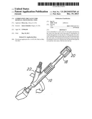
[0013] FIG. 1 is an isometric vieW ofthe tool ofthe inven
tion Which is designed for attachment to the valve stem of a
tire to remove a valve core from the valve stem and retain the
valve core While ?lling sealant and other liquids through the
open valve stem into the tire. The tool also enables replace
ment of the valve core into the valve stem and in?ation or
de?ation ofthe tire Without being dismounted from the valve
stem;
[0014] FIG. 2 is a plan vieW of the tool of FIG. 1;
[0015] FIG. 3 is an exploded isometric vieW of the tool of
FIG. 1;
[0016] FIG. 3A is a pictorial vieW of a locking mechanism
Which ensures engagement or coupling of a piston member
With a valve stem to enable removal ofthe valve core from the
valve stem;
[0017] FIG. 4 is a plan sectional vieW ofthe tool ofFIG. 1;
[0018] FIG. 4A is a partial sectional vieW similar to FIG. 4
depicting engagement of a valve stem by a piston member;
[0019] FIG. 5 is a partial sectional vieW of FIG. 4;
[0020] FIG. 5a is a partial sectional vieW of an alternative
construction ofthe control knob assembly for the tool ofFIG.
5;
[0021] FIG. 6 is a planvieW ofthe tool ofFIG. 1 Whereinthe
tool is positioned for mounting on a valve stem;
[0022] FIG. 7 is an isometric vieW depicting the attachment
ofthe tool of the invention on the valve stem of a tire;
[0023] FIG. 8 is a sectional vieW of the tool depicting the
manner in Which the tool engages the valve core of a valve
stem to Which it is attached;
[0024] FIG. 9 is an enlarged perspective vieW ofthe manner
of engagement of the tool With a valve core of a valve stem;
[0025] FIG. 10 is a sectional plan vieW ofthe tool Wherein
the valve core ofthe valve stem has been engagedto enable air
or gas to be released through the tool;
[0026] FIG. 11 illustrates the mechanism of the tool for
engaging the valve core ofa valve stem prior to release of air
through the valve core to the atmosphere;
11. US 2013/0333769 A1
[0027] FIG. 12 is a sectional vieW similar to FIG. 11
wherein the tool has been manipulated to engage the valve
core of a valve stem in order to release air through the tool
from the tire to Which the valve stern is attached;
[0028] FIG. 13 is a sectional vieW illustrating the removal
ofa valve core from a valve stem by manipulating the tool to
engage the valve core;
[0029] FIG. 14 is a sectional vieW of the tool Wherein the
tool has been manipulated to retract the valve core from the
valve stem subsequent to engagement as illustrated in FIG.
13;
[0030] FIG. 15 is a sectional vieW of the tool Wherein the
valve core has been removed from the valve stem and sealant
is introduced through the tool for ?oW through the valve stem
to the interior of a tire to Which the valve stem is attached;
[0031] FIG. 16 is a sectional vieW ofthe tool Wherein air is
injected throughthe tool to force sealant from the tool into the
tire through the valve stem prior to insertion ofthe valve core;
[0032] FIG. 17 is a sectional vieW illustrating manipulation
of the tool to engage and position the valve core Within the
valve stem subsequent to introduction of sealant through the
tool and to illustrate the forcing ofresidual sealant through the
valve stem due to movement of the valve core;
[0033] FIG. 18 is a sectional vieW of the tool Wherein the
tool is manipulated to engage the plunger ofthe valve core to
open the air passageWay through the tool and the valve stern
for pressuriZing the tire by supply ofair through an air entry
passage;
[0034] FIG. 19 is an enlarged sectional vieW ofthe position
of the valve core prior to engaging the plunger of the valve
core by the tool for injecting of air as depicted in FIGS. 17;
and
[0035] FIG. 20 is a partial sectional vieW illustrating the
engagement of the plunger of the valve core by the tool to
open the air passageWay through the valve core to the interior
of the tire as depicted in FIG. 18.
DETAILED DESCRIPTION OF EMBODIMENTS
OF THE INVENTION
[0036] The attached draWings illustrate an embodiment of
the invention and various alternate aspects ofan embodiment.
FIG. 1 is an isometric vieW of one embodiment ofthe inven
tion. The tool is designed to engage the valve core in the valve
stem ofa tire and cause at least partial de?ation ofthe tire. The
tool may then be manipulated to engage and remove the valve
core from the valve stem ofthe pneumatic tire. The valve core
is then removed from the valve stem and stored Within the
tool. Such removal is effected prior to introduction of sealant
through an auxiliary passage of the tool and the valve stem
into the tire. Subsequently, gas may be injected through the
auxiliary or inlet passage ofthe tool to force sealant inthe tool
through the valve stem into the tire. Then the valve core,
Which had been removed from the valve stem of the tire and
housed Within the tool during sealant ?oW through the tool,
may be reinserted into the valve stem by the means ofthe tool.
The valve core is then engaged and opened by manipulating
the tool to provide a gas ?oW passage through the auxiliary
passage and valve stem into the tire. An external pressurized
gas source, such as an air or nitrogen source, attached to the
separate inlet passage of the tool may thereby inject gas
through the tool and the valve stem to in?ate the tire. Finally,
When the tire is in?ated, the tool may be by unthreading from
the valve stem.
Dec. 19,2013
[0037] The tool includes is a body 10 With a longitudinal
valve core storage passage 12 into Which an annular piston 14
is ?tted. The annular piston 14 includes a central passage 16
into Which a pusher or valve core actuating rod or stem 17 is
positioned. At the outer end ofthe passage 12, a ?rst knob 18
is mounted or attached by a pin or screW 36 in passage 36A to
engage and enable driving or moving the piston 14 longitu
dinally oraxially along axis 27 by pushing orpullingtheknob
18. In one embodiment as shoWn in FIG. 5, upper end 14A of
piston 14 is con?gured in a shape keyed or compatible With
opening 18A ofknob 18 so that upon rotation ofknob 18 the
piston 14 is simultaneously rotated. A stem engaging knob 20
component of knob 18 is slidably ?tted on knob 18 and is
designed to engage the top of the stem or rod 17 to move it
longitudinally Within the cylindrical passage 16 ofthe piston
14. A transverse gas ?oW or gas and sealant inlet connector 22
connects With the longitudinal passage 12 in the body 10.
[0038] Further referring to FIGS. 1 and 2, the gas ?oW or
gas inlet and sealant connector passage 22 is in the form of a
conduit having a ?oW passage 22A With an axis 23. The
passage 22A is connectable to a gas or air source through a
threaded connector 25. The main section of body 10 and
longitudinal passage 12 is comprised of a substantially
straight, linear axis 27 Which forms an angle in the range of
20°-40', preferably in the range of about 25°, With the con
nector passage 22A and axis 23. The connector 22 thus
de?nes a projection from the body 10 Which may be gripped
to facilitate rotation ofthe body 10 about axis 27 When attach
ing or threading outlet end 28 ofthe tool to a valve stem, such
as the valve stem 24 depicted in various ?gures. That is, the
tool is applied to the valve stem 24 by threading it onto the
valve stem 24 at the threaded outlet end 28 of the body 10.
[0039] The component parts of the tool are illustrated in
greater detail in FIG. 3. In one embodiment the knob 18
comprises a generally cylindrical, molded component part
Which slidably receives air knob 20. The air knob 20 includes
generally parallel, longitudinal projecting spaced legs 29 and
30 that ?t over and slide along the outer surface of the knob
18. The range ofsliding motion is restricted by pin 60 ofknob
18 in slot 62 of air control knob 62 (FIG. 4). The legs 29 and
30 terminate at their distal endWithprojecting tabs 32, such as
shoWn in FIG. 18, as tabs 32. The tabs 32 are designed to
engage an annular slot 34 in the upper end of the body 10 or
alternately, in a second embodiment slots 32A Which, upon
depressing air knob 20 longitudinally along axis 27 against
the force of spring 38 and rotation about axis 27, Will engage
and lock slots 34B ofthe air knob 20 With projections 34A as
shoWn in FIG. 3A.
[0040] In the embodiment of FIG. 4, the knob 18, Which is
attached to piston 14, is slidably mounted on the valve core
pusher or rod 17. Further a pin 60 through air knob 20 ?ts in
longitudinal slots 62 in air knob 20 over the upper end ofstem
17 to limit travel ofrod or stem 17 biased axially by spring 38
in the axial direction aWay from end 28. Thus the stem or
pusher 17 ?ts into the generally cylindrical central passage 16
of the piston 14 and is biased by a spring 38 in an axial
direction aWay from the outlet end 28 ofthe body 10. The slot
62 Which engages pin 64 limits the axial travel of stem 17.
Alternately, stem 17 may be keyed to cap 68 at the outer ortop
ofstem engaging knob 20 as shoWn in FIG. 5A. Thus stem 17
Which is biased longitudinally toWard cap 68 by spring 38 is
also keyed to the knob 20 and thus rotates With knob 20 and
12. US 2013/0333769 A1
may move longitudinally against the force of spring 38 inde
pendently from movement ofpiston 14 in the embodiment of
FIG. 4 or FIG. 4A,
[0041] The piston 24 Will generally move inunison With the
pusher or stem 17, except When the slots 62 or slots 62A are
limited by pin 60 ofair knob 20. As explained hereinafter, the
pusher or stem 17 may be extended into the passage 12
independently from the piston 14 to thereby longitudinally or
axially extend and engage a plunger of a valve core 21 to
release air from a tire or to permit the injection of air into the
tire. Thus pusher or stem 17 may move independently in an
axial direction along axis 27 to engage the valve member ofa
valve core 21 in the valve stem 24. TWo embodiments of the
knob construction employing this concept are disclosed;
namely, the approach or structure depicted in FIG. 3 and FIG.
5 as Well as FIG. 3A and FIG. 5A.
[0042] The piston 14 includes multiple O-rings, such as
O-ring 39 in grooves in the outer surface of the piston 14.
Further, the piston 14 includes a projecting end section 40
Which receives a valve core holder 42 retained tightly joined
to the projecting end or ?ngers comprising end section 40 by
means of an O-ring 44. The holder 42, Which is illustrated in
greater detail in FIG. 13, comprises a partially annular mem
ber that includes a slot 70 and is con?gured to ?t under and
engage a plunger 46 ofa valve core 21 and may engage a lug
72 of a valve core 21 to enable release by rotation and
unthreading or threading by reverse rotation ofthe valve core
21. Thus the O-ring 44 positioned around the projecting end
or ?ngers 40 ofthe piston 14 compresses the valve core holder
42 in a manner Which enables it to ?t under the head of the
plunger 46 and grip the plunger 46 as Well as the valve core 22
in a fashion Which enables that valve core 21 to be rotated,
either clockWise or counterclockwise as the piston 14 is
rotated by tWisting knobs 18, 20.
[0043] The body 10 includes a piston brake or stopper 48
Which limits the travel that the piston 14 may move axially
into the body 10, but does not limit the movement ofthe valve
core stem pusher 17. That is, the valve core pusher or stem 17
moves at least partially independently Within the piston 14 in
the manner previously described to engage a valve core
plunger 46. Stem or pusher 17 movement is effected by
engaging the knobs 18 and 20 and depressing those knobs
axially in the direction of the outlet end 28 of the body 10.
This distinction or difference in the axial distance of travel
betWeen the valve rod stem or pusher 17 and the piston 14 is
effected by the axial movement ofknob 20 relative to knob 18
and becomes important inasmuch as it represents the ability
and capability ofthe stem orpusher 17 to independently move
to engage the valve core plunger 46, even though the travel of
the piston 14 is limited by stopper 48. Note that the tabs 32
Which lock in the slot 34 are locked in that slot 34, or groove
34, Whenever the valve core pusher 17 is engaged With a
plunger 46 of a valve core 21. Releasing the tabs 32 from the
groove 34 effects release of the pusher or stem 17 from
engaging the plunger 46 inasmuch as the spring 38 biases the
pusher or stem 17 axially aWay from the valve core 21.
[0044] The operational steps of the use of the tool and the
sequence of potential operations are illustrated beginning
With FIG. 4. In FIG. 4 the knobs 18 and 20 are locked to the
groove 34. More particularly, the tabs 32 are engaged With the
groove 34. In this circumstance, a plunger 46 of a valve core
is effectively engaged and pusher 17 may be depressed to
drain or release air from a valve stem of a tire through the
central passage 16 and the connector passage 22. The distinc
Dec. 19,2013
tion betWeen the positions ofthe end ofthe pusher or stein 17
With respect to engagement ofa plunger 46 ofa valve core 21
is depicted in the sequential FIGS. 11 and 12. FIG. 11 illus
trates the condition of the position of the end of the stein or
pusher 17 Which engages the plunger 46 to permit air ?oW
through the valve core 21.
[0045] Assuming adequate air has been released from the
tire by actuation of the valve core 21 positioned Within the
valve stem 24 by pusher or stem 17, the next step is to insure
that the valve core 21 is properly gripped by the holder 42
mounted at the end ofthe piston 14. Pushing the knobs 18 and
20 doWnWardly effects this operation. The valve core 21
being engaged may be removed by rotating piston 14 and
unthreading or releasing valve core 21.
[0046] FIG. 6 illustrates the manner in Which the piston 14
may be WithdraWn outWardly axially in the passage 12. That
is, as described, the bottom end or holder of the piston 14 is
moved axially doWnWard to engage the valve core 21. This
movement doWnWard is illustrated in FIG. 8. FIG. 9 illus
trates the manner in Which the holder 42 engages the plunger
46 ofthe valve core 21. FIG. 13 illustrates in further detail the
manner in Which the valve core is engaged by the holder 42.
Removal is effected by counterclockWise rotation of the
knobs 18 and 20. The valve core 21 is then lifted into passage
12 to a position Which exposes the gas ?oW passage 21. This
is illustrated in FIG. 15. A sealant source is next attached to
the passage 22A and sealant can then be fed through the
connector 22, central passage 12, valve stem 24 and into the
tire as shoWn in FIG. 15. Subsequently, the sealant source is
removed from connection to the connector 22 as shoWn in
FIG. 16 and air is injected through that passage 22A to trans
fer the residual sealing material through the valve stem 24 in
to the tire. The plunger or piston 14 is then loWered through
the passage 12 forcing the remaining sealant to How into the
tire and the knobs 18 and 20 are manipulated and locked to or
engaged With the tool body 10 by means of the tabs 32
engaging the groove or slot 34. Pusher 17 may engage plunger
46 ofvalve core 21. Engagement causes the plunger 46 to be
opened through the valve core 21 Which has been rotated in
order to reinsert the valve core in the stem. Air may then be
inserted through the connector 22 and passage 22A and the
longitudinal passage 12 at end 28 of the tool into the tire.
[0047] In summary referring to FIG. 3, the piston 14 is
designed to slide Within the passage 12 of the body 10 and
includes an element or clamp at its inner end that engages a
valve core 21 located in a valve stem 24. The engagement
thereof enables the valve core 21 to be rotated in a clockWise
or counterclockWise direction to insert or remove the valve
core 21 from the valve stem 24 and to position the valve core
21 in a distal or spaced relation to the entry in the valve stein
24. The knob 18, 20 is designed to engage and drive the piston
14 and stem 17 longitudinally and to a limited extent inde
pendently.
[0048] The valve core stem or rod or pusher 17, Which is
slidably positioned Within the passage 16 through the piston
14, is designed to engage the head or outer tip plunger 46 of
the valve core 21 in order to release pressure from the tire 26
Which is being repaired. The valve core stem orpusher 17 thus
extends through an opening 28 in the knob 18 and may be
engaged by the air rod drive knob 20 Which is a component of
knob 18.
[0049] In revieW, the sequence of operations When repair
ing a tire is to ?rst place the tool body 10 over the valve stem
24 by threading it onto the valve stem 24. The piston 14 may
13. US 2013/0333769 A1
then be engaged With the valve core 21. The valve core pusher
or rod 17 may then be depressed to release air or gas from the
tire through the valve stem 24. The rod actuating knob 20,
piston knob 18 and piston 14 may then be rotated to release
the valve core 21 from the valve stem 24. The piston knob 18
and integral stein engaging knob 20 may then be axially
WithdraWn to position the valve core 21 from the valve stem
24 into passage 16 ofbody 10. The connector 22 and passage
22A may then be connected to a sealant source. The sealant
Will then ?oW through the passage 22A and valve stem 24 into
the tire.
[0050] Subsequently, the piston 14 and pusher 17 may be
moved axially and longitudinally to reinsert the valve core 21
by appropriately rotating the valve core 21 back into the valve
stem 24. This operation also transports any residual sealant
through the valve stem 24 and into the tire. The connector 22
may then be connected to an air or gas source and the valve
stem 24 depressed by means of movement of the pusher 17
and knob 20. The tire may thus be easily and adequately gas
?lled and pressuriZed. Release of the air engaging knob 20
Will release the valve core 21 from engagement by spring
biased rod or pusher 17. The entire tool may then be removed
from the valve stem 24 by reversing orunthreading the tool 10
from the valve stem 24,
[0051] While there has been set forth an embodiment and
alternatives of the invention, the invention is to be limited
only by the folloWing claims and equivalents.
What is claimed is:
1. A combination tire valve removal and ?uid ?ll tool
comprising:
(a) a valve body including an elongate, generally linear
valve core passage having a valve stem engaging open
end and a piston receiving opposite end, said valve body
further including a lateral ?uid ?oW passage connected
to the valve core passage ofthe body adjacent the valve
stem engaging end;
(b) a valve core removal assembly longitudinally moveable
in the valve core passage; said valve core removal
assembly including a rotatable and longitudinally move
able piston With a center passage, said piston thriller
including a valve stem engaging end and an opposite
manual driven end, said piston further including a valve
core engaging element on the valve stem engaging end
ofsaid piston, said removal assembly further including a
longitudinally moveable stern member in said piston
center passage and a drive assembly at the driven end for
rotational and longitudinally positioning said piston and
stem member in said valve core passage, and for inde
pendently longitudinally moving said stem member in
said piston passage.
Dec. 19,2013
2. The tool of claim 1 Wherein the drive assembly is uni
tary.
3. The tool ofclaim 1 Wherein said drive assembly includes
a body attachment element to limit longitudinal movement of
said drive assembly.
4. The tool of claim 3 Wherein said body attachment ele
ment comprises a prong and said body includes a groove for
receiving said prong guide for rotational movement of said
drive assembly.
5. The tool of claim 1 further including a biasing element
for biasing the drive assembly and stem longitudinally aWay
from the valve core engaging end of the piston.
6. The tool of claim 1 Wherein the valve stem engaging
element comprises an annular gasket compatible With the
valve core plunger.
7. The tool of claim 1 Wherein the body member piston
receiving end includes a stop projection element to limit
longitudinal movement of said piston.
8. The tool ofclaim 1 Wherein the lateral ?uid ?oW passage
section forms an acute angle With the valve core passage.
9. A combination tire valve removal and ?uid ?ll tool
comprising;
(a) a valve body including an elongate, generally linear
valve core passage having a valve stem engaging open
end and a pistonreceiving opposite end, said valve body
further including a lateral ?uid ?oW passage connected
to the valve core passage ofthe body adjacent the valve
stem engaging end;
(b) a valve core removal assembly longitudinally moveable
in the valve core passage;
said valve core removal assembly including a rotatable and
longitudinally moveable piston With a center passage,
said piston further including a valve stem engaging end
and an opposite manual driven end, said piston further
including a valve core engaging element on the valve
stem engaging end ofsaidpiston, saidremoval assembly
further including a longitudinally moveable stem mem
ber in said piston center passage and a drive assembly at
the driven end for rotational and longitudinally position
ing, said piston and stem member in said valve core
passage, and for independently longitudinally moving
said stem member in said piston passage Whereby said
piston engaging element is engageable to a valve core
and rotatable to remove or insert said valve core in a
valve stem, and Wherein said piston and stem member
are longitudinally moveable in said valve core passage
to open and close access to said valve core passage from
said lateral ?uid ?oW passage, and said stein member is
independently longitudinally moveable in said center
passage to open and close a valve core.
* * * * *