1. TECHNICAL SERVICE BULLETIN
SEPTEMBER 2016
Ford Application: Alternator
GenCom and GenMon Signals
The Ford Smart Charge System was introduced in the 1999 Ford Windstar and has
continually evolved to include all applications as well as additional modules, sensors
and strategies. By understanding the alternator command and feedback signals, referred
to as GenCom and GenMon, you’ll be better able to diagnosis charging system
issues. Because charging system codes do not turn on the check engine light, scan tool
diagnosis is always required.
Default Charging
Before conducting any tests, retrieve all diagnostic codes. Diagnostic testing will cause
codes to set, which can later be misinterpreted as a vehicle concern. The alternator
will default charge at ~13.7 volts when there are vehicle concerns with GenCom or
GenMon. Depending upon the type of failure, the PCM may command a high voltage
set point, and then switch to default at timed intervals, making the voltage fluctuate.
To manually put the vehicle in a fixed default mode, disconnect the 3-pin regulator
connector at the alternator, start the vehicle, and increase engine rpm to 2500 briefly.
The alternator will default charge at ~13.7 volts depending upon vehicle electrical
demands. While the vehicle is in default mode, load the alternator and perform power
and ground voltage drop tests.
GenCom Diagnosis
GenCom is the PCM-commanded voltage set point sent to the regulator (within
the alternator). The voltage source for the signal originates at the regulator, and the
PCM modulates the signal to ground with a variable duty cycle signal. The signal
is approximately 128 Hz, but varies based on specific regulator. The duty cycle
command varies from 3 - 95%. The higher the duty cycle, the higher the commanded
voltage set point. It is important to remember that most versions of Ford Smart Charge
will have no command present if the alternator is performing as desired.
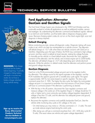
• With the key in the off position, disconnect the 3-pin regulator connector and
measure voltage in the center pin of the regulator (Figure 1). Voltage should be 7.5
volts or higher and is most commonly near battery voltage (regulator dependent). If
voltage is less than 7.5 volts, and the alternator has adequate power and ground,
replace the alternator.
• Reconnect the regulator connector and carefully backprobe GenCom. Start the
vehicle while monitoring duty cycle or DC voltage on the wire.
- On initial startup you may notice a ~3% duty command (~.3 - .5 volts). This start-
up mode reduces engine load during the crank cycle.
- After startup you will see a command anywhere from ~35 – 65% duty cycle (4 –
9 volts). (The exact values are vehicle and system voltage dependent.)
(Figure 1)
Sign up to receive the
Remy Aftermarket
Products Technical
Service Bulletin at
remyautoparts.com
REMINDER: Fully charge
and load test the battery
before beginning. A partially
charged or failing battery
will result in incorrect test
results. Do not have a
battery charger attached
during vehicle testing.
Sense
GenCom
GenMon
2. Technical Support
Monday-Friday, 8am-8pm EST
800-854-0076
tcs@remyinc.com
remyautoparts.com
• Once the vehicle is stable, add loads by turning on the headlamps, wipers and other accessories. The value
should rise in both duty cycle and voltage. Remember, the command may not always be present. If there is no
command, adding loads to the vehicle should always result in a new PCM command.
- If duty cycle and/or voltage remain high and do not fluctuate, check the GenCom wire for an open, or a
potential PCM failure.
- If duty cycle and/or voltage are low and do not fluctuate, check the regulator connector for open, GenCom
for short to ground, and—although very unlikely—a failed PCM.
- If duty cycle and/or voltage respond similar to the above description, GenCom is operating normally.
However, problems in the GenMon circuit can result in GenCom codes because the PCM cannot verify the
command was received by the regulator.
GenMon Diagnosis
GenMon is the alternator load information provided to the PCM by the regulator. The voltage source for the
signal originates at the PCM, and the regulator modulates the signal to ground with a variable duty cycle signal.
The signal is approximately 128 Hz, but varies based on specific regulator. The duty cycle command varies from
5 - 95%. The higher the duty cycle, the higher the load. GenMon should have a signal anytime the alternator is
operating.
• With the key in the off position, disconnect the 3-pin regulator
connector, turn the key to the on position, and measure voltage on the
GenMon pin of the wiring harness connector, (Figure 2). The voltage
should be near battery voltage. If voltage is low check the GenMon
circuit for short to ground or high resistance short. If the harness checks
ok, the PCM is likely failed.
• Turn the key off and reconnect the regulator connector. Carefully
backprobe the GenMon terminal (Figures 1 2). Start the vehicle and
monitor the duty cycle and/or voltage. There is no fixed value—it is
dependent upon battery SOC and vehicle loads. Once the vehicle
has stabilized, add loads. The duty cycle and/or voltage should rise.
Turning off loads should result in a decrease.
- If the duty cycle and/or voltage do not rise and fall with
corresponding changes in loads, inspect the alternator connector,
verify alternator power and ground circuits, and replace the
alternator.
Sense Circuit, B+ Power and Ground Circuits
Fluctuating, low and high voltage can all be caused by the sense circuit, as well as alternator B+ and ground.
These conditions—common in Ford applications—are diagnosed daily by the technical support team. Applied
voltage must match system voltage, and more importantly, voltage drop cannot exceed .5 volts in each of these
circuits.
Need help? Contact Technical Support at 800-854-0076.
Want to learn more? Ask your sales representative about Remy Products training courses.
(Figure 2)