1. Dave Bothman- Faculty Advisor
Stephen Laguette - UCSB ME Department
Alex Russell - Advising Teaching Assistant/Tester
Tyler Ray, Scott Fergusen - Testers
Grant Kimzey - Darren Freitas – Pierre Chesnot – Rhys Freitas – Ryan McQueen
UCSB, in association with the Soh laboratory, is currently involved in
cutting edge microfluidic research. In order to produce these high
end microfluidic devices, researchers have to accurately and
precisely drill holes in silicon wafers and glass microscope slides by
utilizing a bench top CNC mill. Because these microfluidic devices
require such high precision drilling, a time-intensive set up
procedure is essential for optimal results.
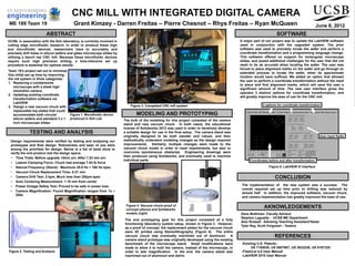
Figure 2. Testing and Analysis
Figure 3. Completed CNC mill system
A major part of our project was to update the LabVIEW software
used in conjunction with the upgraded system. The prior
software was used to precisely locate the wafer and perform a
coordinate transformation and a programming language change.
This software offered no support for rectangular microscope
slides, and posed additional challenges for the user that did not
need to be as accurate when locating the wafer. The user was
forced to place alignment marks on the wafer and go through an
extended process to locate the wafer, when its approximate
location would have sufficed. We added an option that allowed
the user to perform a coordinate transformation without the need
to place and find alignment marks, which will save the user a
significant amount of time. The new user interface gives the
operator 3 distinct options for coordinate transformation, and
will greatly improve the ease of use for the CNC mill.
-Existing U.S. Patents :
US 7155030, US 5857667, US 3833230, US 6167325
-Flashcut 4.0 User Manual
-LabVIEW 2010 User Manual
Design requirements were verified by testing and analyzing our
prototypes and final design. Robustness and ease of use were
among the priorities for design. Below is a list of tests done to
verify the end product met the design specs.
• Time Trials- Before upgrade 15min avr. After 7.53 min avr.
• Lateral Clamping Force- Chuck had average 7.04 lb force
• Natural Frequency (Stand)- Maximum 25.6 Hz < 168 Hz spec
• Vacuum Chuck Replacement Time- 4:21 min
• Camera Drift Test- 2.4µm, Much less than 250µm spec
• Auto Centering Measurement- 1.18 mm from center
• Power Outage Safety Test- Proved to be safe in power loss
• Camera Magnification- Found Magnification ranged from 1x –
200x
June 8, 2012ME 189 Team 19
Figure 1. Microfluidic device
produced in Soh Lab
The implementation of the new system was a success. The
overall required set up time prior to drilling was reduced by
almost half. In addition, the improved software, vacuum chuck,
and camera implementation has greatly improved the ease of use.
Team 19’s project set out to minimize
this initial set up time by improving
the old system in three categories:
1. Replacing a cumbersome
microscope with a sleek high
resolution camera
2. Updating existing coordinate
transformation software via
LabVIEW
3. Design a new vacuum chuck with
replaceable top plates that could
accommodate both circular
silicon wafers and standard 3 x 1
inch microscope slides
The bulk of the modeling for this project consisted of the camera
stand and new vacuum chuck. In both cases, the educational
license of Solidworks 2012 was used in order to iteratively develop
a suitable design for use in the final setup. The camera stand was
originally designed to be both slender and robust, and then
methodically underwent modeling changes as the design required
improvements. Similarly, multiple changes were made to the
vacuum chuck model in order to meet requirements, but also to
overcome spontaneous obstacles. Engineering drawings were
then produced using Solidworks, and eventually used to machine
individual parts.
The end prototyping goal for this project consisted of a fully
functioning laboratory system setup, shown in Figure 3. However,
as a proof of concept, the replacement plates for the vacuum chuck
were 3D printed using Stereolithography (Figure 4). The entire
vacuum chuck was eventually machined out of aluminum. A
camera stand prototype was originally developed using the existing
benchmark of the microscope stand. Small modifications were
made to allow it to hold the camera, instead of the microscope, in
order to test magnification. In the end, the camera stand was
machined out of aluminum and delrin.
Figure 4. Vacuum chuck proof of
concept (above) and Solidworks
models (right)
Coordinates before and after transformation
3 options for coordinate transformation
User input fields
Figure 5. LabVIEW VI Interface