Reduce part count (integrate components, eliminate fasteners)
More maintainable (no loose or missing fasteners)
Lower radar signature (fewer structural discontinuities)
Lighter weight (eliminate fasteners)
Lower cost (less touch labor, eliminate fasteners)
Composites – Metals – Hybrid - Multifunctional
A close relationship with the chemical company Dynamit AG in Troisdorf had developed during the construction of the H II. The materials "Mipolan" and "Astralon" were made available for various curved parts, which worked out so well that it appeared the time had come to try to build an entire aircraft from these new materials.
As a final test, a pair of wings for the primary glider "Hor's der Teufel" were built entirely from synthetic materials. Conventional construction methods were used. Since fewer brackets and other metal parts were needed, a weight saving of 15% was realized, with no loss in strength. The building material consisted mainly of phenol resins; the filler was ordinary paper. No wood at all was used in the wings. The wing bolts were simply inserted into holes drilled in the spar without brackets or bushings. The D-tube was formed by sheets made the same way; the remainder of the wing was fabric covered.
The glider was test flown in May 1936. After the flight tests, one wing was static loaded until it broke, the other left outside without fabric cover for six months, to test its weather resistance. Thereafter it was load tested with special emphasis on its glue joints.
With our new experience, our attention was directed toward the prospects and problems of molded parts, which promised to greatly reduce production time and cost.
Our Air Ministry was interested in a combat aircraft with an unobstructed rearward gun position. The British already had such a machine. Our proposal was a machine with two pusher propellers, and a gun position between them, pointing aft. The Hirth engine factory could deliver an 60 HP engine with both left and right rotation. We would use these on a two place aircraft mat would be tailless, and if possible, a pure flying wing, without a cockpit bubble.
We wanted slow Right characteristics as good as conventional aircraft. This required flaps, which severely altered the pitch moment. To counteract this, we chose rotating wing tips as elevons. A two step leading edge sweepback would approach the ideal parabola shape, and reduce the "Middle-effect" drag.
There were many problems during production. The material would separate due to temperature changes, glue would dissolve protective varnish, insufficient stiffness of molded parts etc.
The first flight assured us that the problems with the "middle effect" was minimal, and the flight was stable. The tests were unfortunately interrupted when an engine failed during takeoff and a wing tip touched the ground, causing a total loss of the aircraft.
It was decided that another H V should be built as quickly as possible, this time from steel tubes and wood to conserve time, while Dynamit A G proceeded with composite material research on their own.
The contrarotating propellers were made of wood, and coated with "Lignofol". These masterpieces were handmade by Peter Kumpel, who also made the "Habicht" propeller.
From (http://www.nurflugel.com/Nurflugel/Horten_Nurflugels/horten_nurflugels.html)
Google search defines Mipolan as an industrial grade linoleum.
Astralon found at www.astralon.com some sort of acetate material?
The second Ho V was started in Cologne in 1937. Our new knowledge about the "middle-effect" allowed us to build a canopy over the cockpit, and put the pilots in a more upright position. It was believed that the uncomfortable reclining position was a contributing factor in the Ho V a crash. We also returned to the normal elevon configuration, and increased the wing span by six feet. The airfoil and the stepped leading edge sweepback were retained. The landing gear was a fixed tricycle type. A split flap on the center section was connected to trailing edge flaps along the inboard half of each wing.
The flight characteristics were excellent in all respects. During landing, a surprising discovery was made; air trapped in ground effect between the deep center section and the flaps rotated the aircraft slightly and lowered it gently to the ground. The pilot needed only to pull the stick all the way back and wait. It was impossible to make a hard landing!
Modifications to single seater (Ho V c) performed in 1942 and flight testing resumed, finally abandoned altogether in 1943, more pressing things in the shop.
Automated tape placement and uni-directional prepreg used to fabricate the 66’ main wing spar of the A400M.
The Polaris A2 had a 1,500 mile range, weighed 32,500 pounds and was 31 feet long. It was the same diameter as the Polaris A1 -- four-and-a-half feet--and could be launched from the same tubes inside a submarine. The first A2 traveled more than 1,400 miles from Cape Canaveral, Florida, when it was launched on November 10, 1960. It became operational on June 26, 1962, with the initial deployment of the Ethan Allen, the first submarine of its class designed from the keel up as an SSBN, a nuclear-powered, ballistic missile submarine.
SPO on 28 November 1958 directed initiation of the second-generation missile, POLARIS A2 (1500 nm), to be loaded on the sixth SSBN in October 1961. The Polaris A2 was dimensionally quite similar to Polaris A1 except the first stage was 30 in. longer. With a total weight 32,500 Ib and a length of 31 ft; the A-2 had a range approximately 1450 nm. The first stage (22,400 lb) used a steel motor case; polyurethane propellant (19,200 lb) with ammonium perchlorate (oxidizer) and aluminum additives. The second stage (9,300 lb) used a fiberglass motor case; composite modified double base propellant (7,400 lb), DDT-70 motor designed by ABL with rotating nozzles and a Mk I guidance system (23S Ib);
To achieve a 1500 nm POLARIS A2, the most obvious way would be to make some components of the missile lighter and improve the performance of the propellants. After evaluating the most practical approach for maximum improvements with minimum risks, it was decided to concentrate on the second stage, reducing its associated inert weights and improving the specific impulse of the second stage motor. Reduction of second stage inert weight would result in eight times more increase of a range increment than a similar reduction in the first stage.
The Alleghany Ballistics Laboratory (ABL) under the operation of Hercules Powder Company, took on the development of an improved propellant, a cast-in-case double base (nitrocellulose/nitroglycerin) propellant to which was added the aluminum fuel and ammonium perchlorate oxidizer. The motor chamber's weight was reduced by the use of a glass filament-wound approach versus steel. It consisted of continuously wound glass fibers with epoxy resins.
With the improvement in propellant in the second stage came an increase of thrust plume temperature. There had been previous problems with jetevators on Al's; so an alternate thrust vector control [TVC] system was developed (e.g., rotatable nozzles). This concept employed a unique feature in that the axis of rotation on each of four nozzles was set at an angle and produced pure axial thrust when the nozzle was in the null position. When the nozzle was rotated about its axis, the jet stream was deflected relative to the centerline of the motor, thus permitting TVC with a minimum loss in axial thrust. Two opposite nozzles fuming together produced a component of side force in the direction toward which they were rotated. If they were rotated in opposite but equal directions, roll-control torque was produced.
In addition to the second stage improvements, the POLARIS A1 first stage motor design was lengthened by 30 in. but the same A1 propellant was retained along with jetevators for TVC.
The A2 missile had considerably less development problems than the A1. The A2, being an extension of the A1 in many aspects, had greater maturity when it entered the flight test stage. With the primary difference in the two missiles being in the second stage motor, it was not surprising, however, that some pre-flight problems should arise in that area of the A2. The new rotating nozzles, replacing the A1 jetevators, had a tendency to stick in static motor tests. Considerable effort was expended to correct this fault. Fortunately, by the time A2X-1 was flight tested, the problem had virtually disappeared. The comparatively few flight anomalies which the A2X experienced were in the main random type failures.
The launch of the first A2X missile at Cape Canaveral on 11 November 1960, signaled the beginning of an extremely successful test program. The entire A2X flight test program consisted of 28 vehicles, of which 19 were successful, 6 partially successful and 3 failures. However, 8 of these A2Xs were reconfigured for the purpose of testing Mk II guidance and reentry vehicle materials (both for A3X application) and these were fired at various times in late 1961 and during 1962. They had designations such as A2G, A2M, and A2MG.
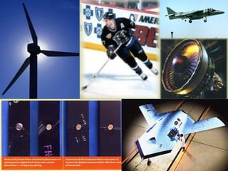
With the advent of the A2X program came the first experience with flame attenuation of radio frequency communications during the boost phase. The new propellant used in SS motors contained a high percentage of aluminum which caused ionized particles in the exhaust plume. When this ionized cloud came between the missile and the ground-based radio frequency facilities, blackout of telemetry, destruct, and tracking functions occurred. The problem was solved by relaying to down-range stations in front of the missile and the ionized plume.
The first successful submerged launch of the POLARIS A2 came from the USS Ethan Allen (SSBN-608) on 23 October 1961 off the Florida coast. On 26 June 1962, the POLARIS A2 began its initial operational patrol when the USS Ethan Allen departed Charleston, South Carolina.
The USS James Monroe (SSBN-622) on 9 January 1968 became the first submarine with POLARIS A2's to enter overhaul and to receive POLARIS A3 capability. The USS John Marshall (SSBN-611) became the last submarine to give up her POLARIS A2's for POLARIS A3 capability when she went into overhaul on 1 November 1974.
Penetration aids for the FBM reentry vehicles came under consideration several times to counter potential improvements in the Soviet's ABM defense system. The first of these Pen-Aids was PX-1 for POLARIS A2 during the 1961 -62 time frame. This was followed by PX-2 for POLARIS A3 during the 1963 to 65 era. These programs consisted of concept studies and testing. In the case of PX-1, the program proceeded through development and into production. One SSBN load of missiles was deployed with PX-1 Pen-Aids but was off-loaded when the perceived ABM threat did not emerge. The range of the A2 was reduced when loaded with PX-1. Offloading restored the A2's capability.
The Polaris A3 missile was the first to have a range for 2,500 miles, and, while like the A2, it was 31 feet long (1.5 in. longer than A2) and four-and-a-half feet in diameter, it weighed 35,700 pounds--4,000 more than the A2. The design of the POLARIS A3 was restricted in size by the volume available in the submarine's (SSBN) launch tube. Thus the A3 was limited to being approximately the same size as A2 but was to fly 2500 nm versus 1500 nm. Therefore, the A3 was basically a new design missile, rather than an evolution, as was A1 to A2.
The first stage (24,600 lb) used a fiberglass motor case and nitroplasticized polyurethane propellant (21,800 lb). The second stage (10,800 lb) also used a fiberglass motor case; composite modified double base propellant (9,000 Ib), EJC (Hercules), and a Mk 11 guidance system (80 Ib). The reentry system consisted of three reentry vehicles which tilted outboard and are ejected by small rocket motor.
The A3's first test flight took place at Cape Canaveral on August 7, 1962,k and the first A3s went on patrol on September 28, 1964, when the USS Daniel Webster began its initial deployment from Charleston, South Carolina. The A3 was the first Polaris to have multiple reentry vehicles.
The 2500 nm range of the POLARIS A3 extended FBM submarines operations to the Pacific Ocean, providing greater sea room and operating area to offset the expanding Soviet anti-submarine capabilities. Another consideration for the POLARIS A3 was the need for improved accuracy from the longer-range and increased-penetrability capability against the Soviet's emerging anti-ballistic missile defense.
To meet these objectives, the A3's design included reentry vehicle concepts, improved guidance, fire control, and navigation systems; penetration aids (PenAids); and missile trajectory shaping techniques. New technologies were also considered such as, advancements in propellants, electronics, materials, and TVC concepts.
Several A2X test vehicles were launched in late 1961 and 1962 for the purpose of testing improved guidance systems and reentry vehicles for the A3. So even before POLARIS A2 became operational, POLARIS A3 design and component testing was underway.
Two POLARIS A1 missiles, AlX-50 and 51, were reconfigured for tests of an advanced TVC system based upon injection of high-density fluid (Freon 114) into the exit cone of the nozzle, creating a shock pattern and causing the main exhaust stream to deflect. On 29 September 1961, this system was successfully demonstrated during second stage flight and, after a second test 2 months later, was chosen as the baseline TVC system for the A3 second stage. The outstanding advantages of the fluid injection system were its low effective inert weight, its insensitivity to the propellant flame temperature, and the negligible constraint imposed on primary nozzle design. At this time, the rotatable nozzle concept was retained for the first stage.
Guidance required significant development with the systems weight and volume allocation set at less than half that allowed in the earlier A1 and A2 missiles. Increased component accuracy was also a requirement at the longer A3 ranges. To demonstrate the effectiveness of the new inertial instruments and a simplified computer mechanization, the proposed system was flown with excellent results on seven special A2 tests during a 1-year period, starting in November 1961.
An attempt was also made to obtain data on reentry vehicle materials. A special A2 flight test missile evaluated the nylon-phenolic ablative heat shield which had been selected following an extensive ground test program.
Also included in the innovations which provided the major gain in performance of the POLARIS A3 over the A2 were improvements in propellants, chamber materials, and alternate velocity control techniques. The first stage chamber material was changed from steel to high-strength resin-impregnated glass roving, and the propellants were changed to formulations with higher specific impulse and density. Another significant development was the replacement of the single warhead with three reentry vehicles at fixed spacings for more efficient target coverage and reduced vulnerability to possible defenses.
The first A3 flight test was conducted at Cape Canaveral on 7 August 1962. Considering the challenge and redesign involved in the development of the A3 missile, it was not until the seventh development flight that complete success was achieved. It was during the A3 development program that the concept of incorporating production components/processing was first introduced into the development phase of a program (A3X- 18) . (This approach was later to be called "production disciplines.")
During June 1963, the A3X was successfully tested for the first time in a tube-launched firing at sea from the USS Observation Island (EAG-154). The first launching of a POLARIS A3 missile from a submerged submarine, the USS Andrew Jackson (SSBN-619), took place on 26 October 1963.
The A3X flight test program started on 7 August 1962 and was completed on 2 July 1964. There were a total of 38 flights, of which 20 were successful, 16 partially successful, and 2 failures. Of the 20 successes, only 15 had successful reentry vehicle operation and ejection. It was only until the 15 A3X flights that the program began to have a continuous series of success. The first stage at Aerojet was plagued, in early phases, by a most negative reaction between the propellant and the nozzles. The inability to retain a set of nozzles for full duration in static firings delayed the beginning of an examination of nozzle rotation. By using a "cooler" propellant ANP 9969 (about 6000 F flame temperature) and by beefing up the nozzles to massive proportions, using tungsten throats, the nozzle erosion problem could be solved, but at the loss of some 90 rim in range. A3X-14, which was launched from EAG-154, suffered "brain scrambling" of its guidance computer, resulting in early dumping of the missile (command destructed at 17 sec). This anomaly was given the code name of CLIP. The phenomenon was found to occur at the time of umbilical disconnect and to be generated at the missile/ground support interface.
The A3X Reentry System had a series of problems which required a major effort to correct. For one, the heatshield (between ES and reentry vehicle structure) lacked structural integrity. On A3X-33 it failed, no doubt due to the thermal environment created by the reentry vehicle rocket blasts, which were more severe than originally calculated. The severe environment was confirmed in heatshield tests at Rye Canyon, under simulated altitude conditions. Deriving from these and other tests, extensive modifications were made to the heatshield to make it stronger.
The POLARIS A3 missile became operational on 28 September 1964 when the USS Daniel Webster (SSBN-626) began her initial operational patrol with 16 A3 missiles. And another milestone was reached on 25 December 1964 when the USS Daniel Boone (SSBN-629) departed Apra Harbor, Guam and began the first Pacific Ocean operational patrol. With all the Eurasian land mass covered by the 2500-mile range of the POLARIS A3 missile, the FBM System became, for the first time, a true global deterrent.
The POLARIS (A3) Operational Test (OT) program which began in September 1965 had effectiveness results which were significantly less satisfactory than those of the A3 DASO. The POLARIS A3 OT program was suspended in January 1966 and on 17 March 1966, RADM Levering Smith (Director, SPO) convened a special A3 Blue Ribbon Committee to investigate. The Blue Ribbon Committee findings and recommendations were provided during 29 August to 2 September 1966. Preparations to implement the recommendations were conducted between September and December 1966. The POLARIS A3 Blue Ribbon Phase II Recertification (corrective action implementation) program began at POMFLANT, Charleston, South Carolina, on all delivered/deployed A3 missiles in February 1967 and was completed prior to the start of the POLARIS A3T conversion program (October 1968). The POLARIS A3 OT program resumed in November 1967 with greatly improved results.
When compared to C4, for the D5 to achieve the longer range with its larger, heavier payload, improvements in rocket motor performance would be required plus reductions in the weight of the missile's components. To improve rocket motor performance, there was a solid-propellant change. The motor case material on the D5's first stage and second stage became graphite/epoxy versus the Kevlar epoxy of C4, an inert weight saver. The TS motor was to be Kevlar epoxy but, midway through the development program (1988), it was changed to graphite/epoxy. The change was a range gainer (reduced inert weight) plus eliminated any electrical static potential associated with Kevlar and graphite. There was also a change in all D5 rocket motor nozzles' throat material from segmented rings of pyrolytic graphite in the entrance and throat of the C4 nozzle to a one-piece integral throat and entrance (ITE) of carbon-carbon on D5. This change was for reliability purposes.
More info: http://www.fas.org/nuke/guide/usa/slbm/d-5.htm
RSRM info: http://www.thiokol.com/rsrm.htm
Hexcel IM7 fiber is the current standard for filament wound solid rocket motors in the U.S. In the late 1970's our standard modulus fibers were first introduced to the solid rocket motor industry in advanced designs for a lighter filament wound case for the space shuttle solid rocket motor and initially for the Trident II (D5) missile. In the early 1980's with the introduction of IM7, intermediate modulus fiber replaced AS4 in the D5. By the late 1980's IM7 had become the standard fiber for the Delta II, Delta III, Delta IV, Pegasus and Titan IV solid rocket motor cases. Our IM7 fiber is now also used in the M51 solid rocket motor, produced in France.
http://www.hexcelfibers.com/Markets/Markets/Space.htm
Delta II comprises a large and growing family of expendable rockets that can be configured as two- or three-stage vehicles, depending on mission needs. Delta II payload delivery options range from about 1-2 metric tons (1,980 to 4,550 lb) to geosynchronous transfer orbit (GTO) and 2.7 to 5.8 metric tons (6,020 to 12,820 lb) to low-Earth orbit (LEO). Two-stage Delta II rockets typically fly LEO missions, while three-stage Delta II vehicles generally deliver payloads to GTO or are used for deep space explorations such as NASA's recent Mars missions.
Delta II DescriptionThe first stage is powered by the Boeing Rocketdyne-built RS-27A main engine and by Alliant Techsystems' solid rocket strap-on graphite-epoxy motors (GEMs) for added boost during liftoff.
Since the start of the program in 1989, Delta II has been launching U.S. Air Force, NASA, and commercial missions with a lifetime reliability record of nearly 98 percent. As of July 2001, there have been 97 Delta II launches, including government and commercial satellite deployments and scientific missions considered space exploration landmarks. Some of these have included Earth observations (EO-1/SAC-C), studies of the solar wind (WIND), stellar particles (STARDUST), asteroid make-up (NEAR), and Earth's geological forces (RADARSAT).
The Boeing-built RS-27A main engine, first used on Delta in 1974, has powered the Delta II since its inception. Three strap-on solid rocket boosters were added to the Delta in 1964, and later the number increased to six. Currently, the Delta II 7925 version uses nine solid rocket graphite-epoxy motors (GEMs) to boost up to approximately 2,200 kg (4,800 lb) to geosynchronous transfer orbit (GTO) and 5,136 kg (11,300 lb) to low-Earth orbit (LEO).
Between late 1996 and early 1999, Delta II rockets launched four NASA missions to Mars, including the widely publicized July 1997 landing of Mars Pathfinder, which sent spectacular pictures of the Martian surface back to Earth.
Info from: http://www.boeing.com/defense-space/space/delta/flash.html
Hexcel IM7 fiber is the current standard for filament wound solid rocket motors in the U.S. In the late 1970's our standard modulus fibers were first introduced to the solid rocket motor industry in advanced designs for a lighter filament wound case for the space shuttle solid rocket motor and initially for the Trident II (D5) missile. In the early 1980's with the introduction of IM7, intermediate modulus fiber replaced AS4 in the D5. By the late 1980's IM7 had become the standard fiber for the Delta II, Delta III, Delta IV, Pegasus and Titan IV solid rocket motor cases. Our IM7 fiber is now also used in the M51 solid rocket motor, produced in France.
http://www.hexcelfibers.com/Markets/Markets/Space.htm
Titan IV, produced and launched for the U.S. Air Force by Lockheed Martin, is the nation's largest, most powerful expendable space launch vehicle. It provides primary access to space for critical national security and civil payloads and is launched from the East and West Coasts.
Titan launch systems have a better than 95% operational success rate. Titan IV is capable of placing 47,800 lb into low-Earth orbit or more than 12,700 lb into geosynchronous orbit - 22,300 miles above the Earth.
Titan IV consists of two solid-propellant stage "O" motors, a liquid propellant 2-stage core and a 16.7-ft diameter payload fairing. Upgraded 3-segment solid rocket motors increase the vehicle's payload capability by approximately 25%.
The first launch of the new, upgraded configuration called the Titan IV B was Feb. 23, 1997. The Titan IV B features upgraded solid rocket motors with three segments instead of seven for greater reliability, and casings of graphite epoxy rather than steel.
http://www.ast.lmco.com/launch_titanIVfacts.shtml
Terminated in FY06 due to budget constraints – cost effectiveness. . .
Helios is a solar-electric UAV flying wing designed to operate comfortably at extreme altitudes. World record on August 13, 2001 sustained flight at an altitude of 96,863 ft for over 40 minutes. “Atmospheric satellite” designed to provide a low cost, rapidly deployable, local access solution for broadband data and other telecommunications applications. . . Lost to in-flight mishap June 26, 2003.
CHICAGO, Dec. 05, 2005 -- The Boeing Company's [NYSE: BA] second canard rotor/wing (CRW) technology demonstrator - the X-50A Dragonfly unmanned air vehicle - has successfully completed a four-minute hover flight at the U.S. Army's Yuma Proving Ground in southwest Arizona. The aircraft reached an altitude of about 20 feet above ground.
Second only to natural gas power plants, wind farms were the largest source of new power built in 2005 (1st Quarter Market Report from the American Wind Energy Assn.) Growth has continued despite concern about radar interference, a known problem that has slowed and even halted some projects. Wind turbines and radar facilities already coexist successfully in locations at home and abroad, such as Warren AFB in Cheyenne, WY and Guantanamo Bay, Cuba.
The Joint Unmanned Combat Air Systems (J-UCAS) program is a joint DARPA/Air Force/Navy effort to demonstrate the technical feasibility, military utility and operational value for a networked system of high performance, weaponized unmanned air vehicles to effectively and affordably prosecute 21st century combat missions, including Suppression of Enemy Air Defenses (SEAD), surveillance, and precision strike within the emerging global command and control architecture.
The J-UCAS program combines the efforts that were previously known as the DARPA/USAF Unmanned Combat Air Vehicle (UCAV) and the DARPA/USN Naval Unmanned Combat Air Vehicle (UCAV-N) programs.