Fuel flow meters Eurosens - Operation manual
•
1 like•501 views

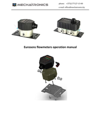
How to choose, install and make service of Eurosens fuel consumption flow meters from Mechatronics

Recommended
More Related Content
What's hot
What's hot (20)
Similar to Fuel flow meters Eurosens - Operation manual
Similar to Fuel flow meters Eurosens - Operation manual (15)
More from Pawel Elenski
More from Pawel Elenski (20)
Recently uploaded
Recently uploaded (20)
Fuel flow meters Eurosens - Operation manual
- 2. EUROSENS Fuel flow meters. Operation manual. ver. 1.6 www.mechatronics.by Page 2 | 30 TABLE OF CONTENTS TABLE OF CONTENTS...................................................................................................................... 2 1. INTRODUCTION .......................................................................................................................... 3 2. DESCRIPTION AND OPERATION OF FLOW METERS ................................................................... 3 2.1. Use .............................................................................................................................................................. 3 2.2. Designation .............................................................................................................................................. 4 2.3. Application ............................................................................................................................................... 4 2.4. Operation parameters and recommendations for model selection.................................... 5 2.5. Dimensions .............................................................................................................................................. 6 2.6. Specification ............................................................................................................................................ 6 2.7. Contents of package .......................................................................................................................... 10 2.8. Flow meter design and operation ................................................................................................ 11 3. WARRANTY............................................................................................................................... 15 4. INSTALLATION RECOMMENDATIONS FOR EUROSENS FLOWMETER ...................................... 16 4.1. Visual inspection of fuel flow meter ............................................................................................ 16 4.2. Estimation of vehicle condition ..................................................................................................... 16 4.3. Common installation recommendations ................................................................................... 17 4.4. Installation schemes of Eurosens fuel flow meters ................................................................ 18 5. DIAGNOSTICS AND TROUBLESHOOTING.................................................................................. 24 6. STORAGE .................................................................................................................................. 28 7. TRANSPORTATION.................................................................................................................... 28 8. UTILIZATION/RECYCLING.......................................................................................................... 29 9. DIMENSIONS............................................................................................................................. 29
- 3. EUROSENS Fuel flow meters. Operation manual. ver. 1.6 www.mechatronics.by Page 3 | 30 1. INTRODUCTION The Operation Manual contains guidelines and rules which refer to Eurosens fuel flow meters (hereinafter Flowmeter), developed by JSC Mechatronics, Vilejka, Belarus (mechatronics.by). The Manual is intended for specialists who are familiar with automobile repair, mounting and maintenance and possess professional knowledge in the field of electrical and electronic equipment of various vehicles. For quality installation and operation it is recommended to train installers in the manufacturing company or in the specialized centers. The installer and the person responsible for the maintenance of flowmeters should know the structure of fuel systems and their operating features. The sources of danger during the installation and operation of the flow sensors are electrical current and working fluid, which can be pressurized to 2.5 MPa and have temperature up to 85 ° C. WARNING! The manufacturer reserves the right to change the technical characteristics of the flow sensors without compromising with the consumer, without leading to a deterioration in their consumer qualities. Installation and deinstallation of flow sensors must be carried out with completely no excess pressure in the pipeline. 2. DESCRIPTION AND OPERATION OF FLOW METERS 2.1. Use Eurosens flowmeters are designed to control a volume flow and the volume of oil products that flow through the flow sensor, operate in frigid and mild climate. The sensors are installed on stationary or mobile units for fuel consumption control and for automatic flow control and regulation in different branches of industry, agriculture and transport.
- 4. EUROSENS Fuel flow meters. Operation manual. ver. 1.6 www.mechatronics.by Page 4 | 30 2.2. Designation Table 1 Brand Type Interface type Autonomous feature Flow rate Доп. функция EUROSENS Delta PN A 250 05. I Number of measuring chambers Output interface Autonomous operation without external power supply Max fuel flow rate in each measuring chamber, liters/hour Improved precision: max error +‐ 0,5% I – LCD display Delta – 2 P or PH – unnormalized pulse (only for Direct) А – possible 100 No symbol – LCD is not installed Direct – 1 PN – normalized pulse No symbol – not possible 250 232 – normalized pulse + RS232 interface 500 485 – normalized pulse + RS485 interface RS – normalized pulse + interface RS232 and RS485 CAN – normalized pulse + CAN interface No symbol – without interface 2.3. Application Use of Eurosens flow meters: current fuel consumption records; registration of machinery working time; normalizing of fuel consumption limitations; fuel theft detection and prevention; real‐time monitoring and fuel consumption optimization; fuel consumption tests for engines.
- 5. EUROSENS Fuel flow meters. Operation manual. ver. 1.6 www.mechatronics.by Page 5 | 30 2.4. Operation parameters and recommendations for model selection Fuel flow meters Eurosens can measure flow of the following liquids: Table 2 Diesel fuel heating oil motor fuel biofuels Other liquid fuels and mineral oil with a kinematic viscosity of 1.5 to 6 mm2 / s. WARNING! 1) All the flowmeters are calibrated for diesel fuel by the manufacturer. If you order it to measure another type of fluid, please indicate its viscosity. 2) When working with the liquid kinematic viscosity of which is more than 6 mm 2/s, the upper limit of the measuring range of flow meters passport will be lower, and the pressure drop across the flow sensor ‐ higher. 3) The amount of impurities in the liquid should be no more than 0.1 mm. 4) Flowmeter is made of materials resistant to gasoline. However, when working with gasoline operation life of flowmeter may be shorter. All risks associated with the safe operation of the Eurosens sensors on petrol engines are assigned to the installer of the equipment. Fuel flowmeters Eurosens Direct(Delta) РN(RS) is a unique equipment that allows to set individually any vehicle (or other type of fuel) with the help of service kit Eurosens Destination, taking into account their individual characteristics (air in the return line, hammering, temperature in the supply and return lines, etc.). Flow sensors Eurosens Delta can be used in differential mode (default setting), and in the summation mode or direct signals delivery from the working chambers (in this case differential flowmeter can measure up to 1000 liters/hour total fuel rate). Methods of settings are described in the service manual (see para.6). Recommendations for Eurosens Direct models selection depending on the power of the engine or boiler productivity. Table 3 Power of engine, KW(HP) Boiler productivity, KW Recommended models Direct XXX PN(PN I, P, RS) Less 100(136) Less 600 100 From 100(136) to 250(340) From 600 to 1200 250 From 250(340) to 600(816) From 1200 to 3500 500 WARNING! 1) It is not recommended to use the flow meter with the max. upper limit.
- 6. EUROSENS Fuel flow meters. Operation manual. ver. 1.6 www.mechatronics.by Page 6 | 30 2) It is recommended to take a final decision on the choice of the model after engine/boiler inspection. 3) Before choosing the model of flowmeter you must choose installation scheme in fuel line (direct measurement or differential). Recommendations for Eurosens Delta models selections depending on the values of fuel consumption in the supply and return fuel lines Table 4 Minimum flow rate , l/h Maximum flow rate, l/h Recommended models Delta XXX PN(PN I), XXX 5 100 100 10 250 250 25 500 500 WARNING! 1) It is not recommended to use the flow meter with the max. upper limit. 2) It is recommended to take a final decision on the choice of the model after engine/boiler inspection. 3) It is not recommended to install the flowmeter when there is an air in the supply or return line, and also in the fuel system with high‐capacity pomp, when the fuel consumption is not large. 2.5. Dimensions See para.10. 2.6. Specification Table 5. Eurosens flow meter modifications Eurosens flow meters Qstart, liters/hour Qmin, liters/hour Qnom, liters/hour Qmax, liters/hour Amount pulses/liter Accuracy Direct PH 100 0,5 2 50 100 98…102 ± 2% Direct PH 250 0,5 5 125 250 98…102 ± 2% Direct PH 500 1,0 10 250 500 48…52 ± 2% Single‐gate Direct PH meters have a pulse output. Are used in the design of the sensors of Direct PH of Waiting. This makes them insensitive to the effects of the external magnetic field and increases the reliability of the flow meter. Table 5. ‐ continue Eurosens flow meters Qstart, liters/hour Qmin, liters/hour Qnom, liters/hour Qmax, liters/hour Amount pulses/liter Accuracy Direct PN 100 0,5 1 50 100 200 ± 1% Direct PN 250 0,5 2 125 250 100 ± 1% Direct PN 500 1,0 5 250 500 50 ± 1%
- 7. EUROSENS Fuel flow meters. Operation manual. ver. 1.6 www.mechatronics.by Page 7 | 30 Eurosens flow meters Qstart, liters/hour Qmin, liters/hour Qnom, liters/hour Qmax, liters/hour Amount pulses/liter Accuracy Direct PN 100.05 0,5 1 50 100 200 ± 0,5% Direct PN 250.05 0,5 2 125 250 100 ± 0,5% Direct PN 500.05 1,0 5 250 500 50 ± 0,5% Direct PN 100 I 0,5 1 50 100 200 ± 1% Direct PN 250 I 0,5 2 125 250 100 ± 1% Direct PN 500 I 1,0 5 250 500 50 ± 1% Direct PN 100.05 I 0,5 1 50 100 200 ± 0,5% Direct PN 250.05 I 0,5 2 125 250 100 ± 0,5% Direct PN 500.05 I 1,0 5 250 500 50 ± 0,5% I ‐ integrated LCD display 05 ‐ higher accuracy PN ‐ meter with an electronic circuit in a powerful STM32 microprocessor. The electronic circuit provides the following benefits: 1. Improved accuracy. 2. Smart processing signals from Hall sensors. 3. The control intervention in the operation of the meter. 4. The flowmeter can measure not only the fuel consumption, but also the derived parameters: the engine is running (boiler), the fuel consumption and the operating time in different modes, during the handling, etc. These parameters can be considered either via the K‐ line interface (PN.) Or via RS232 / RS485 / CAN in RS / CAN flowmeters. 5. PN flow unlike all competitive samples can be installed without the use of a check valve, since the algorithm determines the direction of the fuel flow. This significantly increases the reliability of trouble‐free engine operation with the modified fuel circuit. Table 5. ‐ continue Eurosens flow meters Qstart, liters/hour Qmin, liters/hour Qnom, liters/hour Qmax, liters/hour Amount pulses/liter Accuracy Direct 100 I 0,5 1 50 100 ‐ ± 1% Direct 250 I 0,5 2 125 250 ‐ ± 1% Direct 500 I 1,0 5 250 500 ‐ ± 1% Direct A 100 I 0,5 1 50 100 ‐ ± 1% Direct A 250 I 0,5 2 125 250 ‐ ± 1% Direct A 500 I 1,0 5 250 500 ‐ ± 1% Direct PN A 100 I 0,5 1 50 100 200 ± 1% Direct PN A 250 I 0,5 2 125 250 100 ± 1% Direct PN A 500 I 1,0 5 250 500 50 ± 1% A ‐ autonomous counter, built‐in battery power I‐ integrated LCD display
- 8. EUROSENS Fuel flow meters. Operation manual. ver. 1.6 www.mechatronics.by Page 8 | 30 Direct model flowmeters were intended to display local information, have no pulse output. Requires an external power supply. Flowmeters with index A are also built into the battery and allow the meter to operate independently within three years. Direct Consumption Indicators A single me of the full range of blade switches function instead of the Hall sensor, which is caused by considerations of minimal power consumption. Direct consumption indicators PN A I can be powered either by external power supply and the internal battery. Have a pulse output and display. Table 5. ‐ continue Eurosens flow meters Qstart, liters/hour Qmin, liters/hour Qnom, liters/hour Qmax, liters/hour Amount pulses/liter Accuracy Delta PN 100 0,5 10 50 100 200 ± 1,2%* Delta PN 250 0,5 20 125 250 100 ± 1,2%** Delta PN 500 1,0 40 250 500 50 ± 1,5%*** Delta PN 100 I 0,5 10 50 100 200 ± 1,2%* Delta PN 250 I 0,5 20 125 250 100 ± 1,2%** Delta PN 500 I 1,0 40 250 500 50 ± 1,5%*** Delta PN A 100 I 0,5 10 50 100 200 ± 1,2%* Delta PN A 250 I 0,5 20 125 250 100 ± 1,2%** Delta PN A 500 I 1,0 40 250 500 50 ± 1,5%*** Flows to supply / consumption in liters / hour: * 45/10 ** 90/20 *** 160/30 A ‐ autonomous counter, built‐in battery power I‐ integrated LCD display PN ‐ Normalized pulse. Processor built‐in. The Eurosens Delta Differential Thesaurus has the following unique characteristics: 1. Payment fuel temperature differs in both chambers. 2. The use of Hall sensors provides high reliability and resistance to the external magnetic field. 3. Materials High quality camera and machining allows you to set a 3 year warranty period without limiting the camera resource. 4. Ability to add fuel flow instead of subtraction. 5. Measuring not only the fuel consumption, but also the operating timer, and the operating time and fuel consumption in the partial engine operating modes, which are set limit. Table 5. ‐ continue Eurosens flow meters Qstart, liters/hour Qmin, liters/hour Qnom, liters/hour Qmax, liters/hour Amount pulses/liter Accuracy Direct RS 100 0,5 1 50 100 200 ± 1% Direct RS 250 0,5 2 125 250 100 ± 1% Direct RS 500 1,0 5 250 500 50 ± 1% Direct CAN 100 0,5 1 50 100 200 ± 0,5% Direct CAN 250.05 0,5 2 125 250 100 ± 0,5%
- 9. EUROSENS Fuel flow meters. Operation manual. ver. 1.6 www.mechatronics.by Page 9 | 30 Eurosens flow meters Qstart, liters/hour Qmin, liters/hour Qnom, liters/hour Qmax, liters/hour Amount pulses/liter Accuracy Direct CAN 500.05 1,0 5 250 500 50 ± 0,5% Direct RS 100 I 0,5 1 50 100 200 ± 1% Direct RS 250 I 0,5 2 125 250 100 ± 1% Direct RS 500 I 1,0 5 250 500 50 ± 1% Direct CAN 100 I 0,5 1 50 100 200 ± 0,5% Direct CAN 250 I 0,5 2 125 250 100 ± 0,5% Direct CAN 500 I 1,0 5 250 500 50 ± 0,5% Delta RS 100 0,5 10 50 100 200 ± 1,2%* Delta RS 250 0,5 20 125 250 100 ± 1,2%** Delta RS 500 1,0 40 250 500 50 ± 1,5%*** Delta RS 100 I 0,5 10 50 100 200 ± 1,2%* Delta RS 250 I 0,5 20 125 250 100 ± 1,2%** Delta RS 500 I 1,0 40 250 500 50 ± 1,5%*** Delta CAN 100 0,5 10 50 100 200 ± 1,2%* Delta CAN 250 0,5 20 125 250 100 ± 1,2%** Delta CAN 500 1,0 40 250 500 50 ± 1,5%*** Delta CAN 100 I 0,5 10 50 100 200 ± 1,2%* Delta CAN 250 I 0,5 20 125 250 100 ± 1,2%** Delta CAN 500 I 1,0 40 250 500 50 ± 1,5%*** Flows to supply / consumption in liters / hour: * 45/10 ** 90/20 *** 160/30 I ‐ CAN LCD integrated display ‐ CAN interface RS ‐ RS232 / RS485 interface Eurosens flowmeters can also have a series of RS232 / RS485 data interfaces, as well as the CAN interface by RS232 / RS485 operation of the data interface protocol is possible Eurosens Delta or MODBUS. CAN interface is in accordance with the SAE J1939 specification. Table.6. Main specifications Parameter, measurement units Value Max pressure, MPa 2.5 Nominal pressure, MPa 0.2 Filtering degree of measured fluid, mm, not more than 0.08 Connection thread M14x1.5 M16x1.5 Pressure drop at maximum flow rate, nominal pressure, diesel fuel at 20 °С, MPa, not more than 0.02 Supply voltage range, V from 10 to 50 (from 9 to 32)*
- 10. EUROSENS Fuel flow meters. Operation manual. ver. 1.6 www.mechatronics.by Page 10 | 30 Parameter, measurement units Value Current consumption at 12 V, mA, not more than 50 Current consumption at 24 V, mA, not more than 25 Temperature range, °С from ‐40 to +80** Environment relative humidity at t 40 °C, %, not more than 95 Vibration resistance Max. acceleration to 100 m/s2 in the frequency range from 5 to 250 Hz Resistance to aggressive environments Oil and petrol resistance Electromagnetic compatibility ECE Regulations 10.04 Overall dimensions See para. 10 * for flow meters types Direct P (PH). ** Data is displayed in environment temperature range from ‐20 to +60 °C for flow meters with built‐in display. 2.7. Contents of package Table 7 № Position Quantity 1. Flowmeter eurosens 1 2. Passport 1 3. Cable* 1 * Can be supplied separately.
- 11. EUROSENS Fuel flow meters. Operation manual. ver. 1.6 www.mechatronics.by Page 11 | 30 2.8. Flow meter design and operation 2.8.1.Operation principle The flow sensor measures the amount of fuel flowing through the measuring chamber. Pressurized fluid coming through the inlet nozzle flow sensor in the inlet of the measuring chamber, the piston slides along the inner surface of the chamber and simultaneously slides along the jumper. The piston displaces fluid enclosed in it inside and outside of the piston chamber through its outlet to the outlet port (see. Fig.1). The enclosure provides the orientation of the rotation axes of the cover pin with the magnets and the hub of the piston, thanks to the number of dimensions of the cover and the housing which provides the optimum rotation of the ring chamber. During one rotation of the piston volume of liquid equal to the volume of chamber is displaced. In this case, the electronic position sensors generate pulses as the turnover of the piston, which are transmitted to the electronic control unit for the selected interface. Fig. 1. EUROSENS measuring chamber operation: 1 – inlet, 2 – outlet, ‐ fluid is entering the measuring chamber, ‐ fluid in measurement process, ‐ fluid is going to leave the measuring chamber. 2.8.2.Operation modes Table 8 Flow meter modification Flow rate, l/hour Interference eurosens XYZV, где Y(max. flow rate)= l/hour Normal flow rate Q0 < Q ≤Qmax Tampering The impact of constant magnetic field for more than 10 seconds Idle Normal operation Overload 100 < 2 2‐70 70‐100 > 100 Attempts are fixed 250 < 5 5‐200 200‐250 > 250 500 < 10 10‐400 400‐500 > 500
- 12. EUROSENS Fuel flow meters. Operation manual. ver. 1.6 www.mechatronics.by Page 12 | 30 2.8.3.Information screens (flow meters with LCD display) Table 9 Direct I* Delta I* № Screen Parameter № Screen Parameter 1 2 3 4 5 6 7 8 9 10 11 12 Total consumption, l Idle consumption l Consumption under nominal load, l Overload consumption l Cheat consumption, l / h Negative volume, l Total operating time, Hour** Intervention time, hour *** Flow rate Chamber temperature, deg., C Battery charge,% Firmware version 1 2 3 4 5 6 7 8 9 10 11 12 13 14 15 16 17 18 19 Total consumption, l Idle consumption l Consumption under nominal load, l Overload consumption, l Cheat consumption, l Negative volume , l Total operating time, h ** Intervention time, h*** Supply flow rate, l / h The total volume of supply, l Cheat volume of supply chamber, l Supply flow rate, l / h Temperature in supply chamber, C The total volume of return, l Cheat volume of return chamber, l Return flow rate, l / h Temperature in return chamber, C Battery charge, % Firmware version * These parameters (plus some additional) are also displayed in configuration software on all flow meters PN (RS) (Eurosens Destination service kit is needed). ** for all models, aside Autonomous ***only for Autonomous modifications 2.8.4. Cheat protection features. In order to avoid cheating of flow sensor, its damage or blocking Delta and Direct PN, RS models has the following modes of protection against cheating actions of third parties: 1) Mode "Cheat" ‐ protection against cheating in order to increase the counter value of the consumed fuel (eg. air blowing). Cheat usually leads to a rapid increase in fuel consumption that exceeds the maximum one. Electronic circuit board of a flow sensor detects overstated costs, while fuel meter operation is stopped and counter "Cheat" is activated, which records the amount of fuel flown through the flow sensor at high speed. Mode "Cheat" is automatically exited in few seconds after the normalization of conditions of flow sensor work.
- 13. EUROSENS Fuel flow meters. Operation manual. ver. 1.6 www.mechatronics.by Page 13 | 30 2) Mode "Intervention" ‐ under the influence of an external magnetic field, the flow sensor detects an attempt to interfere and as the result the sensor itself is operating in standard mode and the exposure time is recorded in a special counter "Intervention time." Mode “Intervention” is automatically exited in few seconds after the end of attempts to interfere. 3) Sealing of connections ‐ mounting accessories (fuel connectors, clamps, etc.) supplied by JSC Mechatronics have holes for sealing, that allows to determine the facts of unauthorized interference in the fuel system after the installation of the flow sensor. 2.8.5. Characteristics of the pulse signal of Eurosens Flow meter with non‐standard pulse (model P) has an output pulse signal shown in Fig.2. For each flow meter the number of pulses generated by flowing of 1 liter of fuel through the measuring chamber is shown in the data sheet for the product (passport). The type and characteristics of the output signals EUROSENS X P (PN) ZV are shown in Figures 2, 3 and tables 10, 11 (see below). Characteristics of the output signals EUROSENS X RS ZV match the specified item in the digital protocols. Fig. 2. Output signal of EUROSENS X Р(PH) Z V (also see tables 10,11).
- 14. EUROSENS Fuel flow meters. Operation manual. ver. 1.6 www.mechatronics.by Page 14 | 30 Fig. 3. Output signal of EUROSENS X РN(RS) Z V (also see tables 10,11) Table 10 Output signal of EUROSENS X РN(PH, Р) Z V Modification U high,V U low, V Direct P(PH) 100 0.9Ubat* 0.7 V Direct P(PH) 250 0.9Ubat* 0.7 V Direct P(PH) 500 0.9Ubat* 0.7 V Direct PN (A) 100 0.7(Ubat – 0.4)** 1.4 V Direct PN (A) 250 0.7(Ubat – 0.4)** 1.4 V Direct PN (A) 500 0.7(Ubat – 0.4)** 1.4 V Delta PN (A) 100 0.6(Ubat – 0.8)*** 0.7 V Delta PN (A) 250 0.6(Ubat – 0.8)*** 0.7 V Delta PN (A) 500 0.6(Ubat – 0.8)*** 0.7 V * When the input load resistance (for example, the input of gps‐tracker is near 50 kiloohm) ** When the pull‐up output to power circuit (Ubat) is on for Direct PN. *** When the pull‐up output to power circuit is on (Ubat) for Delta PN. In the latest versions of sensors 0.8(Ubat – 0.8).
- 15. EUROSENS Fuel flow meters. Operation manual. ver. 1.6 www.mechatronics.by Page 15 | 30 Table 11. Output signal of EUROSENS X РN(P) Z V Modification Signal parameters,ms Tpulse max Tpulse min Tlow max (0,6 Tpuls) Tlow max (0,5Tpuls) Tlow max (0,4Tpuls) Tlow min (0,6Tpuls) Tlow min (0,5Tpuls) Tlow min (0,4Tpuls) Direct P 100 9000 180 5400 4500 3600 108 90 72 Direct P 250 7200 144 4320 3600 2880 86,4 72 57,6 Direct P 500 7200 144 4320 3600 2880 86,4 72 57,6 Direct PH 100 9000 180 4500 90 Direct PH 250 7200 144 3600 72 Direct PH 500 7200 144 3600 72 Direct PN (A) 100 18000 180 500 90 Direct PN (A) 250 7200 144 500 72 Direct PN (A) 500 7200 144 500 72 Delta PN (A) 100 18000 180 500 90 Delta PN (A) 250 36000 144 500 72 Delta PN (A) 500 72000 144 500 72 The actual information about the compatibility of particular models of gps‐tracker with Eurosens fuel flowmeters and also the recommendations on their connection and adjustment you can see on our web‐site – www.mechatronics.by 3. WARRANTY 1)The manufacturer guarantees the compliance of Eurosens fuel flowmeters with the present technical requirements, provided that storage, transport and operation conditions are observed, and also the instructions for use that set out in this technical requirement are observed as well. 2)Product warranty period ‐ 36 months from the manufacturing date. 3)Guaranteed storage life ‐ 6 months from the manufacturing date. 4)In case when sensors are supplied as components between enterprises, guaranteed service and storage life should be specified in the Contract between these enterprises. 5)No warranty is made: ‐ if there is a mechanical, chemical, thermal, electric or other damage of device; ‐ in the case of warranty seals and labels absence; ‐ in the case of device breakdown because of inappropriate storage, installation or mishandling; ‐ in the case of device breakdown because of its installation on the vehicle (or other fuel consumer) that is not in good repair or because of device operation on the fuel consumers that are not in good repair, what led directly to the damage of the device; ‐ in the case of opening, repair, installation or modernization of device by unauthorized persons; ‐ when the device operates under conditions that do not correspond to passport characteristics of the device; ‐ In the case when there isn’t held a periodic maintenance in accordance with para.6 of this operation manual;
- 16. EUROSENS Fuel flow meters. Operation manual. ver. 1.6 www.mechatronics.by Page 16 | 30 ‐in the case passport on device (specification) absence. 4. INSTALLATION RECOMMENDATIONS FOR EUROSENS FLOWMETER This section contains general recommendations on Eurosens flowmeter installation. 4.1. Visual inspection of fuel flow meter Before starting flowmeter installation, it is required to inspect it visually for the presence of the possible defects that can be resulted from transportation, storage or careless use: ‐ visible damages of the meter body, fittings, bracket, display, interface cable and connector; ‐ the play of component parts relative to each other and the gaps between them; ‐ immediately before installation it is recommended to check the connection of flowmeter to power supply by the minimal amount of fuel or air supplying (10‐40 lh, pressure – not more than 0.3 atm) and checking the blinking on the sensor cover during the supply of alarm LEds. Contact the supplier if any defects are detected. 4.2. Estimation of vehicle condition Before flowmeter installation the vehicle condition should be estimated to make a conclusion regarding installation possibility. Table 12. Sequence of actions № Action Normal state Recommendations in case of mismatch condition 1. To inspect the fuel lines for damages or fuel leaks No leaks The Customer eliminates the leaks 2. To check the engine operation for (5…10) minutes at idle The engine should work regularly, does not fail (stall); there shouldn’t be any loss of power under load The Customer eliminates the malfunctions 3. To check the engine operation for (5…10) minutes under load or motion The engine should work regularly, foes not fail (stall) The Customer eliminates the malfunctions 4. To check a system voltage by voltmeter For the system voltage 12 V the operating voltage should be in the range of 10 to 18 V. For the system voltage 24 V the operating voltage should be in the range of 10 to 32 V. The Customer eliminates the malfunctions 5. When installing Delta fuel flowmeters ‐ to check if there is an air in return line There shouldn’t be any air It is needed to install Deaerator or The Customer eliminates the malfunctions 6. To check the amount of fuel surpluses, that are removed If the amount of fuel surpluses is significant, the accuracy of To inform the Customer; if possible – to make
- 17. EUROSENS Fuel flow meters. Operation manual. ver. 1.6 www.mechatronics.by Page 17 | 30 № Action Normal state Recommendations in case of mismatch condition from the engine nozzles through the return fuel line measurement decreases, as fuel surpluses flow back in the tank and are recounted by fuel flowmeter amendments in recording system setup 7. To check the pressure in fuel system with the help of manometer Hydraulic resistance of the chosen sensor in nominal mode shouldn’t reduce the pressure by more than 5 % To compare with pressure after flowmeter installation 8. Check the vehicle ground The resistance between connection point and clamp “‐“of battery terminal shouldn’t exceed 1 Ohm. The Customer eliminates malfunctions Vehicle inspection Report should be made and signed based on the inspection results. The customer should eliminate any malfunctions recorded to the report before flowmeter installation. WARNING! 1. The values of maximum and minimal fuel consumption in supply and return lines could be known from the passport or operation characteristics of capacity of the pomp that is installed at the vehicle, or by experimental method – by connection of fuel flowmeter with display (for example, Direct PN A I) to the scheme. 2. It is not recommended to install differential fuel flowmeters in the fuel system with high‐performance pomp and small fuel consumption. For example, if pomp performance is 300 lh, fuel consumption is (5…6) lh and relative measurement error in supply and return lines is 1 %, then the absolute measurement error can be up to 6 lh. What is equal to the amount of fuel consumed by engine. 3. Contraindication to differential flowmeter is the fact of air presence in the supply or return fuel line. 4.3. Common installation recommendations WARNING! This chapter provides the special cases of engine operation schemes. Carefully read the technical documentation of the vehicle on which the flowmeter is installed, before making a decision of its compatibility with the vehicle. To install the flowmeter you need: • a flowmeter • Service kit Eurosens Destination • PC • mounting kit (sold separately); • Hand tools (wrenches, screwdrivers). The flow sensor can be mounted in any position: vertically, horizontally or inclined. Do not kink the cable and fuel pipes (fuel supply lines). It is recommended to mount the sensor
- 18. EUROSENS Fuel flow meters. Operation manual. ver. 1.6 www.mechatronics.by Page 18 | 30 horizontally for the best operation. The sensor should be secured by at least three points on the plane. WARNING! When setting up on a vehicle it is prohibited to drill the base frame! If it's impossible to mount the mounting plate with screws, you can use spot welding. Please observe the following rules: 1. When installing the flowmeter on any equipment in order to avoid the entry of dirt, rubber particles, cord and metals that are resulted from line cutting and thread screwing, IT IS NEEDED to install additional plastic ( or if the pressure in system is high – metallic) fuel filters just before every chamber and the first start‐up to make with them. After half an hour’s working of the system the filters could be accurately dismantled. 2. If the fuel system is highly contaminated, it is needed: ‐ to perform a maintenance work with replacing the regular filter ‐ to install additional filters, if there are no regular ones 3. Flanges and threaded connections must be clean during connection. 4. When installing, use only new copper sealing from the mounting kit. 5. Fuel lines must be protected from external destructive effects. 6. It is not allowed to reduce the internal cross section of the fuel lines on the bends. 7. Fuel hoses on the vehicle must be fixed every 0.5 m. 8. Fuel hoses in length should have a small length margin to compensate temperature changes. 9. Do not install a flow sensor on the elements of the vehicle, subject to strong vibrations and heat. 10. The rubber fuel line should be connected to the fuel system elements with the help of pivot bracket or flow‐through fitting and to be fastened with clamp or crimp sleeve (it is advisable) of required diameter. 11. After flow sensor is installed it is necessary to remove air from the fuel system. 12. All detachable and threaded connections that are situated on the fuel line section “engine – flowmeter, flowmeter –engine” (including a relief valve) should be securely sealed! 13. Do not use flowmeter with maximum flow rate lower than the actual one on the equipped vehicle or diesel generator. 14. It is not recommended to use internal or external filters with petrol gauze (the cell area is less than 0.6 microns) in the wiring scheme. There could be failures in work of fuel system at subzero temperatures. 4.4. Installation schemes of Eurosens fuel flow meters 4.4.1. Typical fuel supply system The most common scheme of the fuel system of diesel engine is shown on the Fig.4.
- 19. EUROSENS Fuel flow meters. Operation manual. ver. 1.6 www.mechatronics.by Page 19 | 30 Fig.4. Typical fuel system Fuel backup pump (hereinafter – supply pump) supplies to the inlet of fuel injection pump (hereinafter ‐ fuel pump) significantly larger amount of fuel than is consumed in each cycle of operation of the engine. Excess fuel from the fuel pump and injectors of the engine is discharged back into the tank through relief valve. 4.4.2 Installation of fuel flow meters Eurosens Direct "On pressure side" scheme Installation of fuel flow sensor Eurosens Direct "On pressure side" scheme intends the installation of a flow sensor between fuel fine filter and fuel pump, where fuel is flown under pressure. Fig.5. Eurosens Direct installation «On pressure side». Check valve is necessary only for “Direct P” serie.
- 20. EUROSENS Fuel flow meters. Operation manual. ver. 1.6 www.mechatronics.by Page 20 | 30 Fuel pump return line should be changed to circulate fuel in a smaller circle: move the return line from the output of the high pressure pump to the fine filter and lock the output of the high pressure pump. For correct operation of the modified fuel system you need to move bypass valve from fuel pump that maintain the required constant pressure (1 ... 1.5) bar in the area of the fine fuel filter and inlet of high pressure pump. At the output of the flow sensor a check valve (0.15 ... 0.5) atm should be installed, which prevents the fuel flow through the flow sensor in the opposite direction, as well as reduces the impact of hydrocracks in fuel system. Thus, excess fuel from supply pump will go back to the tank from the inlet of fine filter and through eurosens Direct will flow only the amount of fuel which is consumed by engine. Advantages of the scheme "on pressure side": • Eurosens Direct is set after the regular fuel fine filter; • Reduced flow resistance on the supply pump suction side. • Return flow heats fuel in the tank. Disadvantages of the scheme "on pressure side": • cooling of fuel pump decreases a little; • return line temperature is lower than in the standard fuel scheme. 4.4.3 Installation of Eurosens fuel flow meter under "suction scheme" Installation of fuel meter "on suction side" supposes the installation of a flow sensor in the area of the fuel system, where the fuel flow is forced by suction created by supply pump. WARNING! Installation of Eurosens Direct flow meter "on suction side" requires an additional fuel filter on the fuel line from the tank to the flow sensor. A special case of Direct flow meter installation under "suction scheme": To install the Direct under scheme "on suction" in the engine fuel system with fuel backup pump (see. Fig.6), it is necessary to use the site between the fuel pre‐filter and the inlet of fuel backup pump.
- 21. EUROSENS Fuel flow meters. Operation manual. ver. 1.6 www.mechatronics.by Page 21 | 30 Fig.6. Installation under scheme «on suction side» with fuel supply pump Under successful operation of the injectors their return flow is not more than 0.1% of fuel consumption, so it can be neglected. To prevent measuring the volume of fuel returned to the fuel tank it is necessary to change the circuit return line. For this special case, it is necessary to change the fuel pump return line so that the fuel is circulated in a small circle without return to the fuel tank. This is done by connecting the return to the input of the fuel supply pump. Thus, to the inlet of supply pump two lines are connected: 1) supply from the tank, passing through the flow sensor; 2) The return fuel pump. Thus, through the flow sensor Direct goes only the amount of fuel which is consumed by the engine. WARNING! One of the advantages of fuel return to the tank through the fuel line is heating the rest of fuel in the tank. Therefore, if vehicles work at low temperatures it is recommended not to change the scheme of the fuel but to use differential flow sensor Delta, or install extra fuel heater. To install Eurosens Direct "on suction side" in the engine fuel system without the fuel supply pump (see. Fig.7), it is necessary to place the flow meter between the fuel pre‐filter and the fuel pump bypass valve. At the same time, an additional fine filter in the area between the place of installation of the flow sensor and the pre‐filter should be installed.
- 22. EUROSENS Fuel flow meters. Operation manual. ver. 1.6 www.mechatronics.by Page 22 | 30 Fig.7. Eurosens Direct «on suction side» installation scheme without fuel supply pump Check valve is necessary only for “Direct P” series. Advantages of the scheme "under suction": minimum intervention in the fuel system easy installation applicable to the most of engines Disadvantages of the scheme "under suction": additional fuel fine filter is needed, that increases the cost of installation; increased pressure on the fuel pump the fuel in the tank isn’t heated by the fuel from the return line (sometimes it is needed to install an additional heater) 4.4.4 Installation of Eurosens Delta under "Differential" scheme In differential scheme the measuring circuit of fuel circulating in the fuel system is not changed. Supply chamber of Delta sensor is installed in fuel supply line, return chamber – in return line. Fuel consumption is thus determined as the difference between the measured values of flows in the supply and return cambers. Particular cases of Delta installation under differential scheme: 1) The supply chamber is installed in the fuel line after supply pump and fine fuel filter (on pressure side). See Fig.8. 2) Supply chamber is installed in the fuel line before supply pump (on suction side). In this case, the installation of an additional fine filter is necessary (see. Fig.9).
- 23. EUROSENS Fuel flow meters. Operation manual. ver. 1.6 www.mechatronics.by Page 23 | 30 Return chamber of Delta flow meter in both cases is installed in return line " high‐ pressure fuel pump inlet ‐ fuel tank." Fig.8. Eurosens Delta installation with supply chamber “on pressure side” Fig.9. Eurosens Delta installation with supply chamber “on suction side” Advantages of differential installation scheme: • No changes in the fuel system; • It can be mounted on the motors under warranty. Disadvantages of the "Differential" scheme: • higher cost; • Higher fuel consumption measurement error;
- 24. EUROSENS Fuel flow meters. Operation manual. ver. 1.6 www.mechatronics.by Page 24 | 30 4.4.5 Electric connection Eurosens fuel flow sensors are powered from on‐board vehicle circuit. WARNING! 1) When connecting Eurosens flow meter to onboard power source it is necessary to connect power “+” and ground “‐” wires to the same sockets where appropriate wires of recording devices are connected. 2) Before starting electrical connection of the sensor special attention must be paid to the quality of the vehicle ground. Resistance between any point of the ground and the negative clamp of the battery must not exceed 1 Ohm. 3) It is strictly recommended to lay Eurosens sensor cable together with standard electrical wiring of the vehicle with mandatory fixing with buckles every 50 cm. Make electrical connection in accordance to the passport for the product. pin circuit Color wires in the cable 1 VBAT green 2 GND black 3 K‐LINE/OUT blue 4 NC no connected 5 NC no connected 6 NC no connected 7 NC no connected Fig.10 Wiring in fuel sensors EUROSENS X P(PH, PN) pin circuit Color wires in the cable 1 VBAT red 2 GND brown 3 K‐LINE/OUT blue 4 RS 232Rx black 5 RS 232Tx white 6 RS 485A yellow 7 RS 485B green Fig.11 Wiring in fuel sensors EUROSENS X RS 5. DIAGNOSTICS AND TROUBLESHOOTING In case of malfunction of flow sensors Eurosens please contact your dealer. Eurosens sensors can be repaired only by certified service center or manufacturer. Initial diagnosis can be carried out by installer in accordance with Fig. 12‐13 (for Direct series) or with Fig. 14‐15 (for Delta series). For several steps the USB Destination 01 may be needed.
- 25. EUROSENS Fuel flow meters. Operation manual. ver. 1.6 www.mechatronics.by Page 25 | 30 It is recommended to contact “Mechatronics” technical support or the nearest service center, all contact you can find on our web‐site: http://www.mechatronics.by/ Fig.12. Simple diagnostics of Eurosens Direct P(PN) flow meters
- 26. EUROSENS Fuel flow meters. Operation manual. ver. 1.6 www.mechatronics.by Page 26 | 30 Fig.13. Simple diagnostics of the Eurosens Direct P(PN) flow meters (continuation)
- 27. EUROSENS Fuel flow meters. Operation manual. ver. 1.6 www.mechatronics.by Page 27 | 30 Fig.14. Simple diagnostics of the Eurosens Delta PN flow meters
- 28. EUROSENS Fuel flow meters. Operation manual. ver. 1.6 www.mechatronics.by Page 28 | 30 Fig.15. Simple diagnostics of the Eurosens Delta PN flow meters (continuation) 6. STORAGE Flow sensors eurosens should be stored in closed, dry premises. Storage of flow sensors eurosens is allowed only in original package at temperature from ‐50 to +40 ° C and relative humidity up to 100% at 25° C. Do not store Eurosens flow sensors in the same room with substances that cause corrosion of the metal and / or contain active agents. Storage life of eurosens flow sensors should not exceed 12 months. 7. TRANSPORTATION It is recommended to transport Eurosens fuel flow sensors in closed transport that provides protection for sensors from mechanical damage and precipitation. Air environment in transportation compartments should not contain acid, alkaline and other aggressive impurities.
- 29. EUROSENS Fuel flow meters. Operation manual. ver. 1.6 www.mechatronics.by Page 29 | 30 Shipping containers with packed flow meters should be sealed. 8. UTILIZATION/RECYCLING Eurosens fuel flow meters does not contain harmful substances and ingredients that are dangerous to human health and environment during and after the end of life and recycling. Eurosens fuel flow meters do not contain precious metals in amount that should be recorded. 9. DIMENSIONS The sizes for different sensor models are shown below in Figures 16, 17. Fig.16. Dimensions of the EUROSENS Direct P (PH, PN, RS, CAN)
- 30. EUROSENS Fuel flow meters. Operation manual. ver. 1.6 www.mechatronics.by Page 30 | 30 Fig.17. Dimensions of the EUROSENS Delta PN (RS, CAN) F – Forward (supply flow), R – Return/(return flow)