More Related Content
Similar to ZapuskalovEnglish
Similar to ZapuskalovEnglish (20)
ZapuskalovEnglish
- 1. 1. Introduction
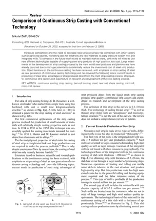
The idea of strip casting belongs to H. Bessemer, a well-
known steelmaker who started from simple tests using two
hardened rolls and a small nine kilogram-capacity
crucible,1)
as shown in Fig. 1(a). A little later, in 1865 he
obtained a patent for the strip casting of steel and iron2)
as
shown in Fig. 1(b).
The first commercial applications of the strip casting
process involved the production of small amounts of mate-
rials with relatively simple casting properties such as cast
iron. In 1934 to 1950 in the USSR this technique was suc-
cessfully applied for casting iron sheets intended for roof-
ing.3–5)
In 1950 J. Hunter and W. Lauener started to cast
strips from aluminum and its alloys.6,7)
The thermal-physical properties of steel make the casting
of steel strip a complicated task and large production runs
are required to make the process profitable.8)
That is why,
despite enormous efforts by researchers, the casting of steel
strip has only recently become feasible.9–12)
Literature based on business, scientific and research pub-
lications on the continuous casting has been reviewed, with
emphasis on strip casting of steel as new generation of con-
tinuous casting technology and covers the following topics:
current trends in production of steel strip; advantages of
strip produced direct from the liquid steel; strip casting
process; strip quality; commercial strip casters and expen-
diture on research and development of the strip casting
process.
The definition of thin strip in this review is 0.1–5.0 mm
thick. The technology of casting thicker strip13–15)
as well as
thinner strip (foils) with an “amorphous” and microcrys-
talline structure,16)
is not the aim of this review. The review
does not include a comprehensive review of patents.
2. Current Trends in Production of Steel Strip
Nowadays steel strip is made at two types of mills, differ-
ing not only in size but also in production “philosophy”.17)
The first type of the mills is the integrated mill with usu-
ally 3–5 million ton per year production capacity.18)
Such
mills are oriented to large consumers demanding high steel
quality as well as large tonnage. Location of the integrated
mills is not bound with their consumers geographically. The
technological basis of the integrated mills is the continuous
casting of slab with thickness ϳ200 mm19,20)
as shown in
Fig. 2. For obtaining strip with thickness of 3–20 mm, the
slab has to run through a large number of processing steps.
Numerous operations of heating and rolling can rectify
some defects inherent in the cast structure and produce
high-quality strip. But this production route has high asso-
ciated costs due to the powerful rolling and heating equip-
ment required and the labor intensive nature of the
process.22)
This type of mill is profitable if the production
tonnage is several million ton per annum.8,23)
The second type of mill includes the mini-mills with pro-
duction capacity of 0.5–2.0 million ton per annum.18,24)
Such mills are located near the customers, who are not in
need of large tonnage and high steel surface quality re-
quirements. The technological basis of the mini mill is the
continuous casting of a thin slab with a thickness of ap-
proximately 50 mm19,25)
as illustrated in Fig. 2. Thin slab
casting reduces production costs by eliminating several pro-
ISIJ International, Vol. 43 (2003), No. 8, pp. 1115–1127
1115 © 2003 ISIJ
Review
Comparison of Continuous Strip Casting with Conventional
Technology
Nikolai ZAPUSKALOV
Consulting, 6/29 Halstead st, Coorparoo, Qld 4151, Australia. E-mail: zapuskalov@inbox.ru
(Receiverd on October 28, 2002; accepted in final form on February 3, 2003)
Increased competition and the need to decrease steel product prices has combined with other factors
such as growing salaries, increasing cost for electricity and raw materials to apply pressure to both mini and
integrated mills. To compete in the future market and to maintain market share, both mills will need to use
new efficient technologies capable of supplying steel strip products of high quality at low cost. Large invest-
ments in the development of strip casting process by the main world steel produces and plantmakers have
already occurred due to its huge potential to substantially reduce the investment cost of steel strip produc-
tion. Open literature on the continuous casting has been reviewed, with emphasis on strip casting of steel
as new generation of continuous casting technology and has covered the following topics: current trends in
production of steel strip; advantages of strip produced direct from the melt; strip casting process; strip quali-
ty; commercial strip casters and expenditure on research and development of the strip casting process.
KEY WORDS: continuous casting; strip casting; twin-roll casting, steel; near net shape casting; mini mill;
micro mill; review.
Fig. 1. (a) Sketch of strip caster was drawn by H. Bessemer in
18561)
and (b) his strip caster patented in 1865.2)
- 2. cessing steps such as hot rolling and intermediate heat-
ing.22,26,27)
At such a mill the production process is com-
pact, easy to control and does not require large investment
in either equipment and personnel.26,27)
However, along
with a shorter processing route, the possibilities of correct-
ing potential defects of the cast slab are also decreased.
That is why only steel of a certain chemical composition is
suitable for the casting of a thin slab.28)
The mini mill is
found to be the most profitable when steel scrap can be
sourced from within a 200-km region around the mill and
products can be sold in a vicinity of up to 500-km ra-
dius.29,30)
The mini mill process is most suited to the pro-
duction of ordinary grades of steel typically medium and
low carbon steels and HSLA grades.31)
The first mini-mill
was built in the USA by Nucor and SMS in 1989.32)
Year by year, the share of mini mills is growing,33)
but in
the near future this growth may slow, due to the following
reasons.
Currently more than half of the metallurgical equipment
operating at large steel manufactures throughout the world
has been in use for over a quarter of a century34)
see Table
1. This equipment should be replaced in the near future. For
companies currently running integrated mills the modern-
ization of existing equipment and processes allows more
rapid cost recovery then investing in the construction of
new mini mills27)
(Fig. 3). This may lead to a partial loss of
the potential market for mini mills.
The other reason concerns the ever-growing application
of electronics in the automotive industry35)
and surface
coating material for steel products,36)
which contaminate
steel scrap with deleterious impurities, such as copper and
tin that are difficult to remove36,37)
(Fig. 4). The price of
steel scrap is estimated to increase by $8 per ton for each
reduction of 0.1% of residual impurities.38)
Therefore, the
price for high quality scrap is likely to rise in the fu-
ture.38,39)
Since the mini mills product cost strongly depends
on the steel scrap price18,40)
as illustrated in Table 2, this is
likely to further retard investment in mini mills. Each of
these reasons is motivating the development of a new gen-
eration of mini mills.
The owners of integrated mills are also investing heavily
in the development of new technology.18,41)
Lately, the
structure of steel demand has undergone serious changes.
The competitiveness of steel producers depends a lot on
product cost and the ability to make products satisfying
specific customer demands.42)
In the conditions of large-
scale production it is difficult to offer a wide range of steels
designed for individual and small consumers. The current
steel market demands a wide variety of steel grades with
different properties, surface appearance and geometry. This
is particularly true for stainless grades.43)
Additionally, to-
day’s stainless steel producers are not able to offer their
products on a long-term basis and at fixed prices because of
a strong dependence on the prices of alloying elements such
as nickel and chrome, which regularly fluctuate.41,44)
To sat-
isfy market demands, integrated steel mills require technol-
ogy advances that will allow the low-cost production of a
diverse range of small, high-quality lots.10,41)
Additionally, increasing substitution of light alloys in the
packaging, automotive and construction industries as alter-
native materials to steel have applied pressure to the steel
producers to reduce production costs to maintain market
share.18,35,45)
Thus increased competition and the need to decrease
steel product prices has combined with other factors such
as growing salaries, increasing cost of electricity and raw
materials to apply pressure to both mini and integrated
mills.17,46–48)
To compete in the future market, both mills
will need to use efficient technologies capable of supplying
ISIJ International, Vol. 43 (2003), No. 8
© 2003 ISIJ 1116
Table 1. Crude steel capacity, utilization, age and replacement potential of existing steel production facilities.34)
Fig. 2. Strip manufacturing processes. (Update from Ref. 21).)
- 3. ISIJ International, Vol. 43 (2003), No. 8
1117 © 2003 ISIJ
Fig. 3. Backward integration using existing hot and cold rolling
of integrated mill: (a) schematic view; (b) comparison of
return on investment of a new thin slab casting and
rolling facility and backwards integration of an existing
conventional rout of integrated mill. Where Investment
cost effectiveϭInvestment costϪCost savings for clos-
ing of slab storage, Number of years before return on in-
vestmentϭInvestment cost effective/(Cash cost savings
relativeϩSales bonus for improved product).27)
Fig. 4. Prediction for development of tin and copper
content of scrap in futures.36)
Table 2. The effect of scrap price on the cost of producing liquid steel (per ton of liquid steel).18)
- 4. steel strip products of high quality at low cost.
3. Advantages of Strip Produced Directly from the
Melt
The strip production costs increase steeply as the final
product thickness decreases and the initial slab thickness
increases.49)
In the processing of a thin slab, the production
costs start to increase dramatically if rolling a strip of thick-
ness below 1.2 mm.50)
However the strip casting process al-
lows strip to be produced at a thickness less than 1.8 mm at
a stable cost.50,51)
Traditional casting machines with oscillation moulds are
unsuitable for the casting of thin steel strip. As the thin strip
solidifies rapidly52)
it should be cast at higher speed, howev-
er as the speed increases, friction on the mould surface in-
creases greatly (Fig. 5) and defects like surface cracks may
form.53–56)
In the traditional casting methods the techniques of
mould oscillation and lubrication with slag at the
mould/slab interface are used to reduce friction. These
techniques cannot be used for strip casting as oscillation re-
sults in marks on the surface and interactions with the slag
may leave defects of a size comparable to the strip thick-
ness.56)
By moving the mould at the same velocity as the strip,
friction problems can be removed. As the mould surface
moves together with the solidifying melt the friction be-
tween them is almost absent so the thin strip can be cast
with good surface quality.57–59)
3.1. Economic Advantage
The production of thin strip directly from the melt allows
eliminating all process steps from the production route
leaving only cold rolling mills and a few finishing opera-
tions, as shown in Fig. 2. Shortening the process route re-
duces investment cost by 4 to 10 times.22,26,60)
Specific in-
vestments per one ton of steel are expected to decrease by
40%, as compared with the conventional production
process (continuous casting and downstream hot rolling).22)
However, as for any new technology, there is some uncer-
tainty and business risk associated with the commercial im-
plementation of the strip casting process. The business risk
is mainly bound with two issues: the strip quality, which is
discussed below, and the operation cost. The success of the
strip casting technology in commercial application depends
on operating costs, which are likely to be higher than those
involved with traditional production routes, particularly in
the commercialization stages.22)
Expected costs are summa-
rized in Table 3. An accurate calculation of operation costs
is still difficult because of uncertainties in the life of key
components of the caster such as ceramic materials and
rolls in full-scale commercial operations. In commercial ap-
plication it is expected that the service life of ceramic mate-
rials is no less than three consecutive heats each of them
110-ton.12)
The time required for changing the rolls is esti-
mated at no longer than 10 min.12)
The accurate calculations of the production costs also de-
pend on the steel grade and its final application.
As for stainless steel, it is anticipated that one-ton of
steel will be US$50 to 150 cheaper in the case of casting
strip compared to that of the casting of thin slabs.61)
Money
is also saved due to lower transportation costs.51,61)
In stain-
less steel production, the ingot is typically cast at one plant,
delivered to another plant for rolling and after that returned
for finishing.29,62)
In the production of low-carbon (0.06 wt% C) cast strip,
only US$20 to US$35 per ton can be saved by strip casting
compared to thin slab casting.61,63)
Lower savings are attrib-
uted to a more efficient technological route and the produc-
tion cycle is contained in one location. The savings that can
be made in strip casting are possible due to the higher con-
centrations of residual impurities, and subsequently cheaper
scrap, that can be tolerated in this process.63)
Because the slag is not applied, the melt comes into di-
rect contact with the roll surface and is solidified at a rela-
tively high cooling rate64)
(see Table 4). During solidifica-
tion, the elements dissolved in the melt do not have enough
time to segregate, and therefore the concentration of resid-
ual impurities may be raised without any harmful effects on
strip quality. In the case of the thin slab casting, for surface
cracks to be prevented, steel scrap is not to contain more
than 0.15 wt% Cu, and 0.015 wt% Sn.28)
In the strip casting
scrap with 3.5 times higher concentration of Cu, up to
0.55%, and with 10 times higher concentration of Sn up to
0.16% can be tolerated.51)
3.2. Energy and Environment
Apart from economic savings, the new casting technique
is more energy efficient and has less environmental impact.
From semi-commercial application of the strip casting in
Krefeld (Germany) within the framework of the Eurostrip
project showed that the energy consumption per one ton of
product is 7.5-times lower (0.4 GJ) than in the conventional
continuous casting–hot rolling route (3.2 GJ).11)
These find-
ings are tentative because they depend on geographic loca-
tion, production structure and steel grade mix. For example,
the energy savings are 2 to 5 times more in the production
ISIJ International, Vol. 43 (2003), No. 8
© 2003 ISIJ 1118
Table 3. Cost comparison for steel strip product with different routes.22)
Fig. 5. Influence of casting speed on friction force between os-
cillation mould and slab.53)
- 5. of stainless steel than in the production of carbon steel.61)
An increase in the ratio of the surface-to-mass by over 40
times (see Table 4) results in an intensive heat transfer to,
or from, the environment and fast cooling, or heating, of the
cast strip. This circumstance permits the as cast strip to be
heated-up, if necessary, to the required temperature in a
short time which additionally reduces the energy consumed
for reheating and lowers steel loss due to scale.27,60,76,77)
The elimination of several intermediate reheating opera-
tions and shorter reheating times allows a reduction in dele-
terious gas emissions per one ton of cast steel: CO2 by ϳ7
times (from 185 to 25 kg), NOx by 15 times (from 290 to
10 g) and SO2 by 3 times (from 50 to 15 g).11)
So, applica-
tion of the strip casting technology allows a reduction in the
total volume of deleterious emissions such as CO2, SO2,
NOx of between 70 and 90% in comparison with the con-
ventional process.78)
3.3. Strip Manufacturing–Industry Structure
Cast strip of 1 to 5 mm in thickness considerably short-
ens the length and duration of the production process route
see Fig. 2 and Table 4. Thus, according to the data,78)
the
production of strip, starting from casting till cooling, takes
no more than 15 min with a 60 to 150 m-long process line.
A plant with such a short production route does not require
a large investment and is very flexible, easily adjusting for
different steel grades, which may be required in small lots.
By numerous estimates, these advantages will stimulate the
construction of a new type of mill, the micro mill.72,79)
The
term and trademark of “Micro-MillsTM
” have already been
formally registered for the type of plant based on the strip
casting process.12)
It differs from the mini mill, which is
based on the continuous casting of thin slabs. The micro
mills can produce steel of better quality with the same or
even lower price compared to the conventional thin slab
casting process. The flexibility of the process will make it
possible to be more accurate in meeting individual cus-
tomer requirements in terms of steel grade composition,
batch size and delivery time.62)
The strip casting technology can also give advantages to
the existing integrated mill. The strip casting process may
be incorporated in an integrated mill which has an excess
steelmaking capacity to increase the range of steel
grades.72)
So, the new process offers substantial possibilities for
steel producers and consumers of steel flat products.
4. Strip Casting Process
Late in the 1980 s, out of the whole variety of strip cast-
ing methods based on a movable mould principal,24,80)
two
techniques were selected for further research and develop-
ment: feed of the melt to the surface of the rotating roll
(spinning technique) and casting into the gap between two
rolls rotating toward each other (twin-roll casting tech-
nique).24,26,81–84)
The main argument in favor of the single-
roll strip casting was the accumulated practical experience
obtained in the development of production steel strip with
amorphous or microcrystalline structure. But asymmetrical
crystallization and an inability to control the quality of the
free surface of the cast strip in the single-roll, has seen this
technique become abandoned and main efforts focused on
the twin-roll technique.85)
An extra advantage of the twin-
roll technique is the higher production rate against the sin-
gle-roll technique.85)
The productivity of the twin-roll caster
is estimated at about 0.5 million ton per annum.73)
Param-
eters of different casters are summarized in Table 5.
Figure 6 shows schematically the typical twin-roll caster
and the controlled parameters of the casting process. The
steel melt flows through the ceramic nozzle to the gap be-
tween the rolls rotating toward each other. Side dams are
used for forming the melt bath in the roll gap. In the
process of the rolls rotation, a steel shell is being solidified
adjacent each roll surface and the two shells meet and weld
together before exiting the roll gap and as a result form the
strip.
ISIJ International, Vol. 43 (2003), No. 8
1119 © 2003 ISIJ
Table 4. General parameters of conventional slab, thin slab and strip casting.
- 6. For the shells to be welded, a roll separation force is ap-
plied.57,114)
Without the roll separation force, the shells are
not welded and the molten steel flows through the roll gap
(Fig. 7). In the case of high roll separation force, like in the
hot rolling process, the strip is deformed and forward slip
appears71,115)
(Fig. 7). In strip casting the temperature distri-
bution across the strip is less even than that experienced
during hot-rolling. This results in higher deformation in the
strip casting in comparison with conventional hot rolling
process.116)
The rate of deformation in the casting direction
is dependent on many variables,102)
and may be greater in
the backward direction than in the forward direction.117)
Too high a pressure causes excessive strip deformation
and this is not desirable as it leads to segregation of low-
melting point elements that crystallize late in solidifica-
tion.71,105)
The temperature of the molten steel for casting is kept as
low as possible for increasing the production rate70)
(Fig. 8)
and reducing surface crack formation.118)
However, it can
be beneficial to control the temperature cycle of the melt
prior to casting as it is possible to increase the strip quality
ISIJ International, Vol. 43 (2003), No. 8
© 2003 ISIJ 1120
Table 5. Parameters of strip casters.
Fig. 6. Schematic view of strip caster with controlled parame-
ters.82)
Fig. 7. Influence of the roll separation force on state of the cast-
ing process and the strip forward slip.71)
- 7. by decreasing segregation and internal stresses in the
strip119)
(Fig. 9).
The productivity of a strip caster depends on casting
speed and the thickness of the strip. The analysis of the
available data for commercial scale casters plotted as
productivity versus casting speed is shown in Fig. 10
which gives a regression relation of Productivity–Casting
speedϪ0.5
.
The scattering of the data from the average linear fit may
be explained by differences in the roll diameter, the surface
coated material and the roll surface micro-topography (see
Table 5).
Larger diameter rolls have a deeper bath melt pool, a
higher capacity to absorb heat and increase the production
rate.88)
Additionally the length of the deformation zone be-
tween the rolls increases with the roll diameter and this cre-
ates a more stable casting process.102)
However the upper
diameter of the rolls is limited by the practicalities of de-
signing a ceramic nozzle to deliver the melt. Additionally,
the higher the diameter of the rolls the larger and more ex-
pensive are the ceramic side dams necessary for containing
the melt. The analysis of the commercial casters shows that
there is still no consensus on the optimal roll diameter.
Castrip uses rolls of 0.5 m in diameter while Nippon prefers
1.2 m and Eurostrip 1.5 m (see Table 5).
Analysis of the actual roll surface material and roll sur-
face micro topography used in the commercial scale casters
is not possible at present as it is a commercially sensitive
features of the caster design which determines not only the
productivity of the caster but also contributes to the total
quality of the cast strip. The available information on the
roll surface features published in the open literature result
from fundamental or general studies and is reviewed below.
The ceramic side dams whose life and price affect the
profitability of the caster are one of the most expensive
components of the caster.121)
The dam should be tight
against the roll ends, wear-resistant, sustain an enormous
temperature gradient between the cold roll end and liquid
steel. Boron nitride-based ceramics have been found to be
the most suitable material.122,123)
5. Strip Quality
Casting strip of thickness 1–2 mm leaves almost no pos-
sibility for additional treatments to rectify its quality, more-
over, additional processing can eliminate all the economic
advantages of the strip casting process.124)
For these rea-
sons, the requirements on the surface quality, geometry and
properties of the cast strip are high.64)
The high casting ve-
locity and rapid solidification demand an accurate control
of any process parameters because even slight deviations
lead to a substantial deterioration of the strip quality.
5.1. Surface Cracks
In continuous casting practices it is known larger heat
fluxes drastically increase the possibility of surface crack-
ISIJ International, Vol. 43 (2003), No. 8
1121 © 2003 ISIJ
Fig. 8. Influence of melt superheat temperature on constant so-
lidification of shell growth.70)
Shell thicknessϭ(Constant solidification)·(Solidification
time).1/2
Fig. 9. Effect of liquid steel preparation by temperature cycle (a)
and (b) on segregation across strip thickness, strip surface
roughness and internal stress in as cast strip.119)
Area of
hysteresis cycle is used as indication of internal stress.
The bigger area represents the higher internal stress.
Fig. 10. Relation between speed of strip casting and productivity
of caster per hour, per meter of roll width. The thickness
of cast strip and casting speed are taken from
data.9,11,75,91,108)
The density of steel is accepted as 7.8
ton mϪ3
from Ref. 120).
- 8. ing by induced additional internal stress during solidifica-
tion.125)
The critical heat flux, which, if exceeded, causes
cracks on low- and middle-carbon steel strip, is indicated in
Fig. 11.
As mentioned previously, slag is not required as a lubri-
cant in the strip casting process. Although slag reduces fric-
tion at the roll surface, it increases the heat flux to levels
several times the critical level shown in Table 4. This in-
creases the difficulty of ensuring high-quality strip from the
strip casting process.
The problem can be solved by a combination of mea-
sures.126)
Selection of a coating material100,127)
in combina-
tion with a special roll surface roughness,64,108,126,128)
roll
separation force129)
and a protective atmosphere108,130)
per-
mit heat flux and internal stress to be lowered and made
more uniform. Different materials based on nickel, chrome
or ceramics92,126)
are applied as coatings. The effect of the
roll surface roughness and the protective inert atmosphere
on the appearance of surface cracks is shown in Fig. 12.
Turbulent flows131)
and ripples on the melt surface132)
may cause cracks on the strip surface. The nozzle must be
designed to lower the amplitude of surface waves133)
as
shown in the design of the submerged nozzle134)
in Fig. 13.
The ceramic nozzle must also be inert with respect to the
melt otherwise surface defects will appear.64)
Reducing the
roll separation force is one of the measures used to prevent
surface cracks.99,105)
5.2. Uneven Strip Thickness
During casting the rolls are not uniformly heated, chang-
ing their initial profile.112)
At operating temperature the roll
profile has to be stable and shaped to ensure uniform thick-
ness of strip with minimum irregularities and good flatness.
A correctly designed roll profile combined with a water-
cooled roll sleeve of an optimal thickness and material, per-
mits thickness irregularities to be minimized3,110,112,135)
as
shown in Fig. 14.
Another reason for irregularities in thickness is due to
the different heat transfer conditions at the side dams com-
pared to the central part of the roll. This causes more irreg-
ularities in the thickness at the strip edges.64)
To rectify the
strip geometry a hot rolling mill is installed in line before
the coiler and the strip edges are trimmed as shown Fig. 15.
Table 6 gives the tolerances of the cast strip thickness re-
quired according to standards in various countries for hot
rolled products. To be an acceptable alternative to hot
rolling, strip casting must produce products that meet or ex-
ceed these standards.
5.3. Strip Flatness
The out of the cast strip flatness may be characterized by
ISIJ International, Vol. 43 (2003), No. 8
© 2003 ISIJ 1122
Fig. 11. Influence of heat flux in mould on longitudinal surface
cracks obtained for low (0.05 wt% C) and middle
(0.11 wt% C) carbon steel.125)
Fig. 12. Relation between crack length per unit area of strips and
roll surface roughness for casting in argon and nitrogen
atmospheres.108)
Fig. 13. Submerged nozzle.134)
Fig. 14. Influence of thickness of the roll sleeve on total roll de-
flection and the shape of the strip profile.112)
The result-
ing roll deflection is calculated as: (Resulting roll de-
flection)ϭ(Bending deflection)Ϫ(Thermal deflection).
- 9. (A/S)ϫ100%, where (A) is the amplitude of a strip devia-
tion from the flat surface and (S ) is the wavelength. The out
of flatness may be caused by uneven thermal and structural
changes taking place in the strip during crystallization and
cooling and non-uniform plastic deformation in the roll
gap. Table 6 gives the flatness of the hot-rolled product re-
quired in various standards. As for surface thickness these
standards must be within the capabilities of the strip casting
process. Deterioration of strip flatness after hot rolling oc-
curs due to non-uniform deformation across the width of
the cast strip.136)
The strip flatness is improved by cold
rolling with tension applied by the coiler.136)
6. Commercial Strip Casters
For the last twenty years different steelmaking companies
have been developing the strip casting technology. Some
projects were stopped and others united in order to reduce
finical expenditure. The companies’ cooperation and the
status of the projects are presented in Fig. 16.
ISIJ International, Vol. 43 (2003), No. 8
1123 © 2003 ISIJ
Fig. 15. Main strip casters: (a) The basic component of BHP-IHI caster136)
used by CASTRIP. (b) Eurostrip.87)
(c)
Nippon Steel Corporation and Mitsubishi Heavy Industries.137)
Table 6. Thickness and flatness variation of as cast strip in comparison with standard tolerance requirements for different countries.
Data for as cast strip taken for low carbon steel with strip width 1 345 mm.136)
- 10. Five commercial-scale casters have been built for esti-
mating the process feasibility and evaluating techno-eco-
nomic parameters: BHP-IHI (Australia), Nippon Steel-
Mitsubishi Heavy Industries (Japan), Myosotis (France),
Acciai Speciali Terni (Italy) and Eurostrip (Germany).
Three of the casters are being intensively prepared for full-
scale commissioning: Castrip (USA), Eurostrip (Germany)
and Nippon Steel–Mitsubishi Heavy Industries (Japan).
6.1. Castrip
Broken Hill Proprietary Ltd., (BHP), an Australian steel-
maker, and Ishikawajima-Harima Heavy Industries (IHI), a
Japanese machine-builder, have studied strip casting since
1989.75)
In 1995 a full-scale machine for casting carbon
steels was constructed in Port Kembla, Australia. For test-
ing properties, parts of the cast strip were cold rolled to
0.42 mm, coated with 55%AlϩZn and applied as roofing in
housing as well as for the production of square 25ϫ25,
50ϫ50 mm and round 21.3–88.9 mm-diameter tubes.75)
Table 7 presents the properties of the cast strip from low-
carbon steel.
In March 2000, Nucor joined BHP-IHI and established
Castrip Limited Liability Company (Castrip LLC), with
Nucor and BHP each owning 47.5% and 5% owned by
IHI.12)
Having obtained the first license from Castrip, in
spring 2002 Nucor completed the construction and started
production operations of cast strip in Crawfordsville,
Indiana, USA.
The basic component of BHP’s caster Fig. 15(a) were
dismantled and delivered from Australia, to the USA. A
110-ton electric arc furnace (EAF) is used for steel melting.
The plant is designed for production of carbon steel and
stainless strip. To develop the strip casting process, Nucor
is going to spend an additional US$100 million.12)
The tar-
get of Castrip is to ensure the stability of cast strip produc-
tion quality firstly for carbon steel and later for stainless
steel. The main application of the low-carbon steel strip is
for roofing, tanks, power unit boxes, furniture frames, etc.
At present the Castrip technology is protected by 1 500
patents worldwide.72)
After the technology is proven, the
company intends to sell it and will continue to invest in
technology to cast wider and thinner strips.139)
ISIJ International, Vol. 43 (2003), No. 8
© 2003 ISIJ 1124
Fig. 16. Company collaboration and status of projects138)
(Nippon Yakin Kogyo Co. Ltd. named as Nippon).
Table 7. Properties of a strip obtained through conventional and cast strip technological routes.
- 11. 6.2. Eurostrip
In September 1999, after several years of independent
R&D on strip casting, Thyssen-Krupp Steel, Usinor and
Voest Alpine Industrieanlagenbau established Eurostrip, a
European company11,79)
(see Fig. 15(b)). The companies
task is to develop a commercial technology for stainless
and carbon steel strip casting.11)
A strip casting shop was
built at the Krupp Thyssen Nirosta plant in Krefeld,
Germany.41)
The plant produces stainless steel and has no
hot rolling facilities. Therefore the strip casting shop is in-
corporated as a missing link in the production route be-
tween the steelmaking and cold rolling shops.87)
Eurostrip has a second commercial-scale caster located
in Terni, Italy, which is used for developing the casting of
carbon and silicon steels.86,87)
Before the merger with
Thyssen-Krupp, Acciai Speciali Terni (AST) and Centro
Sviluppo Materiali (CSM), a research institution in Terni,
Italy, carried out investigations using this commercial-scale
caster.89)
The strip casting fundamentals are being studied
using a laboratory caster located in Aachen University of
Technology (RWTH), Aachen, Germany.11)
Early in 2003 it is planned to bring the Krefeld mill to
the full capacity with a production rate of 0.4 million ton
per annum.86,87)
Currently more than 1 000 patents protect
the Eurostrip technology.78)
The properties of the cast stain-
less strip are presented in Table 7. The stainless steel strip
will be used for kitchenware and sinks.
6.3. Nippon Steel Corporation and Mitsubishi Heavy
Industries
Nippon Steel Corporation, a steelmaker, and Mitsubishi
Heavy Industries, a machine-builder, have pursued a R&D
program aimed at casting stainless steels since 1985.95)
In
1997, a commersial machine for casting of austenitic stain-
less steel was constructed at Nippon Steel’s Hikari Works
(Japan)140)
(Fig. 15(c)). In 1998, the casting unit reached a
capacity of 20 000 ton per month.63)
In 1996 the project cost
was estimated at ¥11 billion141)
($110 million63)
).
For technological improvements, in 2000 Nippon Steel
and POSCO, a Korean company, which has long been car-
rying similar studies, formed an agreement to share in the
research and development of strip casting technology.142)
6.4. SMS Demag and MAIN AG/MTA, Danieli
In August 2000, an agreement on the start of construc-
tion of a full-commercial scale caster for the production of
stainless and carbon steel strip was signed between SMS
(Germany) and MAIN AG/MTA (Switzerland).143)
There has been substantial interest in the strip casting
process by a variety of supporting industries that would
benefit from the large scale commercialization of the new
technology. For example Danieli, a large manufacturer of
plant equipment has indicated their interest and the first in-
dustrial strip caster for carbon and stainless steel with a ca-
pacity of 0.6–0.7 million ton per annum is being built at
ABC (Italy).144)
7. Expenditure on Research and Development of Strip
Casting Technology
A substantial reduction of deleterious emissions and en-
ergy savings in the replacement of traditional technology
with strip casting process is expected. The new technology
is actively supported by several national governments with
the help of state organizations: European Coal and Steel
Community (ECS) in Europe, US Department of Energy in
the US, and The Canadian National Research Council in
Canada. It must be noted that governments provided finan-
cial support only at early R&D stages, which involved fun-
damental investigations. A transition from pilot to commer-
cial production in the conditions of stiff competition and
large potential profits has resulted in companies carrying
out independent, self-funded research projects and restrict-
ing access to any results. Table 8 illustrates the sources of
ISIJ International, Vol. 43 (2003), No. 8
1125 © 2003 ISIJ
Table 8. Expenditure on research and development of strip casting technology and share of government support.
- 12. funding for the development of the strip casting process.
The total cost of the studies, inclusive of fundamental but
indirectly connected research, is somewhat higher. For in-
stance, in the European Union alone, in the period from
1986 to 1999, through the ECS, about US$18 million138,147)
was spent on strip casting, 20% of the whole budget of
US$89 million allocated for the entire R&D related to cast-
ing, including fundamental R&D147)
(for easier conversion
US$1ϭ C= 1).
8. Conclusion
Increased competition and the need to decrease steel
product prices has combined with other factors such as
growing salaries and the increasing cost for electricity and
raw materials to apply pressure to both mini and integrated
mills. To compete in the future market and to maintain mar-
ket share, both mills will need to use new efficient tech-
nologies capable of supplying steel strip products of high
quality at low cost. Large investments in the development
of strip casting process by the main world steel produces
and manufacturers of plant equipment have already oc-
curred due to its huge potential to substantially reduce the
investment cost of steel strip production, which is now at a
stage of industrial implementation for the production of
stainless and low-carbon steels
The technology is well suited for micro mills, which can
produce steel strip of composition required by individual
customers. Comparatively small investments, flexibility and
the low environmental impact nature of the new technology
permits it to be introduced in regions with relatively small
resources of raw materials, for example, in regions which
have sufficient supplies of metallic scrap. The strip casting
technology can also give advantages to the existing inte-
grated mill. The strip casting process may be incorporated
in an integrated mill, which has an excess steelmaking ca-
pacity to increase the range of steel grades.
REFERENCES
1) H. Bessemer: J. Iron Steel Inst., (1891), 1.
2) H. Bessemer: US Patent 49053, July 25, (1865).
3) V. V. Gusev: Liteinoe Proizvodstvo, (1952), No. 11, 5.
4) S. Shiozawa, T. Kusakawa and Y. Matsuura: Sosei to Kako, 1
(1960), 99.
5) M. Cygler and M. Wolf: Iron Steelmaker, 13 (1986), No. 8, 27.
6) W. E. Stephens and G. R. Vassily: Light Metals 1971, The
Metallurgical Society, New York, (1971), 535.
7) D. Altenpohl and P. J. Uggowitzer: Aluminium, 77 (2001), No. 10,
754.
8) M. M. Wolf: BHM, 145 (2000), No. 1, 35.
9) K. Yanagi, K. Sasaki, K. Yamamoto, H. Takeuchi and H.
Nakashima: Mitsubishi Heavy Ind., Tech. Rev., 33 (1996), No. 1,
26.
10) S. Watanabe: Nippon Steel Tech. Rep., 71 (1996), October, 1.
11) H.-U. Lindenberg, U. Albrecht-Fruh, M. Walter, R. Capotosti, G.
Stebner and D. Senk: Forum-Technische Mitteilungen Thyssen
Krupp (English Edition), (2000), December, 20.
12) R. Wechsler: Steel Times, 229 (2001), No. 1, 23.
13) A. J. Hulek and O. Harrer: Metall. Plant Technol. Int., 3 (1997), 84.
14) R. Nystrom, W. Reichelt and M. Dubke: Scand. J. Metall., 29
(2000), No. 3, 93.
15) K. Schwerdtfeger, K.-H. Spitzer, J. Kroos, P. Funke and K.-H.
Hower: ISIJ Int., 40 (2000), 756.
16) H. Jones: Rapid Solidification of Metals and Alloys, The Institute
of Metallurgists, London, (1983), 83.
17) H. Wiesinger: Iron Steelmaker, 24 (1997), No. 12, 33.
18) R. M. Cyert and R. J. Fruehan: The Basic of Steel Industry,
Meeting the US Industry Faces the 21st Century, US Department of
Commerce Office of Technology Policy, Pittsburgh, (1996), 62.
19) E. Schulz, D. Ameling, B. Gerstenberg, E. Hoffken, K. H. Peters
and R.W. Simon: Metall. Plant Technol. Int., 13 (1990), No. 5, 32.
20) M. M. Wolf: 75th Steelmaking Conf. Proc., ISS, Warrendale, PA,
(1992), 83.
21) M. Tsukigahora, H. Sakaguchi, K. Sasaki, S. Suzuki, T. Kato and
M. Tanigawa: The Hitachi Zosen Tech. Rev., 54 (1993), No. 2, 2.
22) C. Hendricks: Metall. Plant Technol. Int., 18 (1995), No. 3, 42.
23) W. Bald, G. Kneppe, D. Rosenthal and P. Sudau: Steel Times Int., 24
(2000), No. 5, 16.
24) A. Trupiano: Metall. Ital., 89 (1997), No. 7–8, 31.
25) T. Watanabe: Tetsu-to-Hagané, 88 (2002), No. 3, 107.
26) J. P. Birat, R. Steffen and S. Wilmotte: European Commission
Technical Steel Research, EUR 16671 en (1995), 198.
27) A. Flick, G. Lettmayr, A. Wagner and A. Bumberger: Steel Times
Int., 24 (2000), No. 3, 17.
28) S. L. Wigman and M. D. Millett: Scanijet VI; 6th Int. Conf.
Refining Processes, MEFOS, Lulea, Sweden, (1992), 1.
29) P. Nilles: Metall. Plant Technol. Int., 17 (1994), No. 3, 46.
30) B. V. Molotilov, A. A. Brodov and V. I. Matorin: Steel in
Translation, 27 (1997), No. 9, 1.
31) J. Aylen: Steel Times, 229 (2001), No. 7–8, 227.
32) H. Malinowski: Steel Times, 217 (1989), No. 11, 600.
33) D. Ameling: Stahl Eisen, 120 (2000), No. 9, 27.
34) H. Wiesinger: Steel Times, 228 (2000), No. 8, 299.
35) C. Fine, R. Clair, J. Lafrance and D. Hillebrand: The US Auto-
mobile Manufacturing Industry, US Department of Commerce
Office of Technology Policy, USA, (1996), 102.
36) K. Noro, M. Takeuchi and Y. Mizukami: ISIJ Int., 37 (1997), 198.
37) L. Savov and D. Janke: Metall., 52 (1998), No. 6, 374.
38) J. J. Poveromo: Proc. of Gerald Heffernan Int. Symp. on Innovative
Technology for Steel and Other Materials, CIM, Montreal, Canada,
(2001), 39.
39) J.-P. Birat: Rev. Métall., Cah. Inf. Tech., 98 (2001), No. 1, 19.
40) S. Millman: Steel Times, 228 (2000), No. 1, 20.
41) R. Barrett: Met. Bull. Monthly, 369 (2001), September, 18.
42) J.-P. Birat: Ironmaking Steelmaking, 28 (2001), No. 2, 152.
43) A. Otto: Symp. Stainless Steel in Architecture, The European
Stainless Steel Development Association, Berlin Germany, (2000),
2.
44) H. Pariser: Met. Bull. Monthly, 369 (2001), September, 12.
45) T. Smith: Steel Times, 217 (2001), No. 5, 168.
46) R. Vondran: Steel Times, 227 (1999), No. 8, 303.
47) C. P. Manning and R. J. Fruehan: JOM, 53 (2001), No. 10, 36.
48) H. Mueller: Steel Times Int., 26 (2002), No. 7–8, 46.
49) I. M. Pavlov: Theory of Rolling, Metallurgizdat, Moscow, (1950),
610.
50) S. Buchanan: Met. Bull. Monthly, 363 (2001), March, 10.
51) J. Vaugh and D. Varcoe: SEAISI Quarterly, 30 (2001), No. 1, 46.
52) D. Senk, B. Engl, O. Siemon and G. Stebner: Steel Res., 70 (1999),
No. 8–9, 368.
53) T. Koyano, O. Terada, S. Uchida and M. Ishikawa: Proc of the 69th
Steelmaking Conf., ISS, Warrendale, PA, (1986), 449.
54) M. Suzuki, H. Mizukami, T. Kitagawa, K. Kawakami, S. Uchida
and Y. Komatsu: ISIJ Int., 31 (1991), 254.
55) M. M. Wolf: BHM, 145 (2000), No. 7, 270.
56) M. Suzuki, M. Suzuki and M. Nakada: ISIJ Int., 41 (2001), 670.
57) J. P. Birat, P. Blin, J. L. Jacquot, P. Riboud and B. Thomas: Rev.
Metall., Cah. Inf. Tech., 86 (1989), No. 11, 919.
58) R. Fukase, A. Nomura and H. Kato: Japanese Patent JP3-128149,
(1991).
59) J. C. Yoon, H. K. Moon, J. T. Duncombe and M. Rushforth:
METEC Cong. 94 2nd European Continuous Casting Conf., 6th
Int. Rolling Conf., Düsseldorf, Germany, (1994), 435.
60) B. Lindorfer, K. Schwaha, J. Spiess and G. Houze: Steel Times, 221
(1993), No. 7, 304.
61) T. Bagsarian: New Steel, 14 (1998), No. 12, 56.
62) A. Ritt: New Steel, 16 (2000), No. 1, 20.
63) J. Isenberg-O’Loughlin: Thirty-Three (33) Metal Producing, 36
(1998), No. 12, 20.
64) W. Blejde, R. Mahapatra and H. Fukase: Belton Memorial Symp.
Proc., ISS, Warrendale, PA, (2000), 253.
ISIJ International, Vol. 43 (2003), No. 8
© 2003 ISIJ 1126
- 13. 65) H. Legrand, J. M. Damasse, M. Espenhahn, R. W. Simon and G.
Stebner: THERMEC 97 Int. Conf. on Thermomechanical
Processing of Steels and Other Materials, TMS, Warrendale, PA,
(1997), 2.
66) M. Wolf: Steel Times Int. (Contibuous Casting Supplement), 19
(1994), No. 3, 4.
67) R. W. Simon, D. Senk, C. Mollers, H. Legrand, L. Vendeville and J.
M. Damasse: Metall. Plant Technol. Int., 3 (1997), June, 78.
68) M. Wolf and W. Kurz: Proc. Int. Conf. on Solidifacation and
Casting of Metals, The Metal Society, London, (1977), 287.
69) J. K. Brimacombe and I. V. Samarasekera: Iron Steelmaker, 21
(1994), No. 11, 29.
70) H. Fukase, W. J. Folder and W. Blejde: European Patent
EP0627275, (1994).
71) Y. Fujita, H. Sato, T. Kitagawa, S. Nishioka, Y. Tsuchida and A.
Ozeki: ISIJ Int., 29 (1989), 495.
72) P. Campbell and R. L. Wechsler: Heffernan Symposium, Ontario,
Canada, (2001), 201.
73) P. Campbell, W. Blejde, R. Mahapatra and G. Gillen: 59th
Electrical Furnace Conf. and 19th Process Technology Conf. Proc.,
ISS, Warrendale, PA, (2001), 727.
74) Anonymous: Steel Times, 228 (2000), No. 7, 256.
75) W. Blejde, R. Mahapatra and H. Fukase: METEC Cong. 99, VDEh,
Düsseldorf, Germany, (1999), 176.
76) O. Kubaschewski and B. E. Hopkins: Oxidation of Metals and
Alloys, Butterworths, London, (1962), 319.
77) K. Brown and M. Assefpour: Steel Times, 221 (1993), No. 12, 524.
78) Thirty-Three (33) Metal Producing, 40 (2002), No. 1, 18.
79) T. Bagsarian: New Steel, 16 (2000), No. 12, 18.
80) T. Kusakawa: Trans. Iron Steel Inst. Jpn., 26 (1986), B-123.
81) A. W. Cramb: Iron Steelmaker, 15 (1988), No. 7, 45.
82) J. P. Birat and R. Steffen: Metall. Plant Technol. Int., 14 (1991), No.
3, 44.
83) J. K. Brimacombe and I. V. Samarasekera: Moden Steel Processing,
39th Canadian Chemical Engineering Conf., Hamilton, Ontario,
Canada, (1989), 104.
84) J. P. Birat: Ironmaking Steelmaking, 14 (1987), No. 2, 84.
85) N. Jacobson, B. Hollinger and H. Fredriksson: Scand. J. Metall., 22
(1993), No. 2, 75.
86) M. Walter, G. Stebner, J. M. Damasse, P. Tolve and G.
Hohenbichler: Steel Times Int., 25 (2001), No. 7, 33.
87) H.-U. Lindenberg, J. Henrion, K. Schwaha and G. Vespasiani: Stahl
Eisen, 121 (2001), No. 12, 97.
88) H. Legrand, U. Albrecht-Fruh and A. Flick: 85th Steelmaking Conf.
Proc., ISS, Warrendale, PA, USA, (2002), 211.
89) P. Tolve, R. Tonelli, R. Capotosti and G. Hohenbichler: THERMEC
’97 Int. Conf. on Thermomechanical Processing of Steels and
Other Materials, TMS, Warrendale, PA, (1997), 2.
90) A. Mascanzoni, J. M. Damasse and G. Hohenbichler: Steel Times
Int., 25 (2001), No. 8, 45.
91) H. Legrand and G. Martel: Steel Times, 226 (1998), No. 3, 104.
92) J. M. Damasse, D. Themines and L. Vendeville: Rev. Métall., Cah.
Inf. Tech., 97 (2000), No. 1, 43.
93) T. Furukawa: New Steel, 10 (1994), No. 10, 42.
94) Steel Times, 227 (1999), No. 4, 128.
95) K. Yanagi, K. Yamamoto, H. Takatani, K. Sasaki, Y. Wakiyama, H.
Takeuchi, H. Nakashima, S. Tanaka, M. Yamada and Y. Yamakami:
METEC Cong. 94 2nd European Continuous Casting Conf. 6th Int.
Rolling Conf., Düsseldorf, Germany, (1994), 423.
96) M. Yukumoto and H. Yamane: ISIJ Int., 35 (1995), No. 6, 778.
97) S. Miyake, H. Yamane, M. Yukumoto and M. Ozawa: ISIJ Int., 31
(1991), 689.
98) M. Mohri, K. Onishi, K. Yamada and N. Nishinae: THERMEC ’97
Int. Conf. on Thermomechanical Processing of Steels and Other
Materials, TMS, Warrendale, PA, (1997), 2.
99) D. Senk, G. L. Thompson, W. Bleck, P. Vicente, R. Kopp and R.
Steffen: European Commission Technical Steel Research, EUR
19364 en, (2000), 132.
100) J. C. Grosjean, J. L. Lacquot, J. M. Damasse, H. Litterscheidt, D.
Senk and W. Schmitz: Iron Steelmaker, 20 (1993), No. 8, 27.
101) H. Fiedler and M. Jurisch: Stahl Eisen, 111 (1991), No. 2, 79.
102) M. Badowski, L. Hentschel, R. Kopp, W. Schmitz and D. Senk:
Steel Res., 72 (2001), No. 11ϩ12, 484.
103) D. Senk, C. Schneider and R. Kopp: Rev. Métall., Cah. Inf. Tech.,
87 (1990), No. 4, 351.
104) A. Girgensohn, A. R. Buchner and K. Tacke: Ironmaking Steel-
making, 27 (2000), No. 4, 317.
105) A. R. Buchner and J. W. Schmitz: Steel Res., 63 (1992), No. 1, 7.
106) J. T. Choi, H. T. Chung, W. S. Kim and H. K. Moon: 83rd
Steelmaking Conf., ISS, Warrendale, PA, (2000), 29.
107) H. K. Moon, C. M. Park, H. N. Cheong, C. G. Lee and T. Kang:
Proc. Merton C. Flemings Symp. on Solidification and Materials
Processing, TMS, Warrendale, PA, (2001), 507.
108) D.-Y. Choo, S. Lee, H.-K. Moon and T. Kang: Metall. Mater. Trans.
A, 32A (2001), 2249.
109) A. L. Robson, J. Wilkinson and G. L. Thompson: METEC Cong.
94 2nd European Continuous Casting Conf., 6th Int. Rolling Conf.,
Düsseldorf, Germany, (1994), 443.
110) G. L. Thompson, S. R. Higson and P. J. Longdon: European
Commission Technical Steel Research, EUR 18608 en, (1998), 49.
111) B. V. Molotilov, N. M. Zapuskalov and V. T. Timofeev: Steel USSR,
21 (1991), No. 12, 565.
112) N. Zapuskalov and M. Vereschagin: ISIJ Int., 38 (1998), 1107.
113) J. D. Hwang, H. J. Lin, W. S. Hwang and C. T. Hu: ISIJ Int., 35
(1995), 170.
114) H. Litterscheidt, R. Hammer, C. Schneider, R. W. Simon, D. Senk,
R. Kopp and B. Hehl: Stahl Eisen, 111 (1991), No. 2, 61.
115) M. S. Boichenko, I. M. Pavlov, A. A. Korolev, J. M. Bokshitskii and
S. I. Irodov: Metall., (1940), No. 5, 11.
116) N. M. Zapuskalov: Dissertation, TSNIICherMet, Moscow, (1992),
163.
117) K. Miyazawa, T. Choh and M. Inoue: J. Jpn. Inst. Met., 46 (1982),
944.
118) S. K. Ray, B. Mukhopadhyay and S. K. Bhattacharyya: ISIJ Int., 36
(1996), 611.
119) N. M. Zapuskalov, B. V. Molotilov, G. A. Srebrianskii and S. S.
Golovanenko, Russian Patent N 1799674, (1993).
120) A. Jablonka, K. Harste and K. Schwerdtfeger: Steel Res., 62 (1991),
No. 1, 24.
121) T. Kuster: New Steel, 12 (1996), No. 11, 68.
122) B. R. Marple, S. Poudrette and F. G. Hamel: 75th Steelmaking
Conf. Proc., ISS, Warrendale, PA, (1992), 353.
123) P. Fournier and F. Platon: Wear, 244 (2000), 118.
124) K. Shibuya and M. Ozawa: ISIJ Int., 31 (1991), 661.
125) S. Hiraki, K. Nakajima, T. Murakami and T. Kanazawa: 75th
Steelmaking Conf. Proc., ISS, Warrendale, PA, (1994), 397.
126) A. Buchner and H. Zimmermann: Steel Res., 73 (2002), No. 8, 327.
127) A. Sanz: Surface and Coating Technology, 146–147 (2001), 55.
128) L. Strezov and J. Herbertson: ISIJ Int., 38 (1998), 959.
129) M. Ha, J. Choi, S. Jeong, H. Moon, S. Lee and T. Kang: Metall.
Mater. Trans. A, 33A (2002), 1487.
130) T. Mizoguchi, K. Miyazawa and Y. Ueshima: Tetsu-to-Hagané, 80
(1994), No. 1, 36.
131) H. Yasunaka, K. Taniguchi, M. Kokita and T. Inoue: ISIJ Int., 35
(1995), 784.
132) S. Tanaka, I. Suichi, S. Ogawa, T. Furuya, K. Sasaki and K. Yanagi:
75th Steelmaking Conf. Proc., ISS, Warrendale, PA, (1991), 809.
133) R. P. Tavares and R. I. L. Guthrie: Can. Metall. Q., 37 (1998), No.
3–4, 241.
134) European Patent EP0515075B1, (1992).
135) R. Tonelli, L. Sartini, R. Capotosti and A. Contaretti: METEC
Cong. 94 2nd European Continuous Casting Conf., 6th Int. Rolling
Conf., Düsseldorf, Germany, (1994), 20.
136) W. Blejde, R. Mahapatra and H. Fukase: Iron Steelmaker, 27
(2000), No. 4, 29.
137) T. Tanaka: CAMP-ISIJ, 15 (2002), 208.
138) E. Luiten, Ph.D. Thesis, Utrecht University, Utrecht, (2001), 300.
139) R. Wechsler: IISI-35 Conf., International Iron and Steel Institute,
(2001) (from www.castrip.com).
140) T. Furukawa: Am. Met. Mark., 106 (1998), No. 217, November, 3.
141) Anonymous: Iron Steel Eng., 73 (1996), No. 4, 77.
142) R. McCulloch: Met. Bull. Monthly, 370 (2001), No. 10, 10.
143) Steel Times, 228 (2000), No. 10, 354.
144) Steel Times Int., 26 (2002), No. 4, 26.
145) Steel Times, 228 (2000), No. 11, 387.
146) C. S. Kuo: Minerals Yearbook, Vol. 3, International Minerals
Statistics and Information, Korea, (1994), 713.
147) J. Ball: Ironmaking Steelmaking, 27 (2000), No. 2, 91.
ISIJ International, Vol. 43 (2003), No. 8
1127 © 2003 ISIJ