1. 1
ABOUT THE COMPANY
RICO is a world- class engineering group supplying a wide range of high precision fully
machined aluminum and ferrous components and assemblies to automotive OEMs across the
globe. RICO’s integrate services include design, tooling, casting, machining, assembly and R&D
across ferrous and aluminum products.
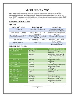
RICO GROUP OF INDUSTRIES
TABLE 1.1
COMPANY NAME PARTNERSHIP PRODUCTS
FCC RICO 50% FCC & 50% RICO Clutch assembly –two
wheelers and four wheelers
CONTINENTAL RICO 50% CONTINENTAL &
50% RICO
Hydraulic Brake products and
services
MAGNA Powertrain RICO 50% MAGNA Powertrain &
50% RICO
Oil pump and Water pump
RICO JINFEI 92.5% RICO & 7.5% JINFEI Aluminum Alloy Wheels-
Two Wheelers
RICO USA& UK 100% RICO Assembly, logistics,
Customer support
TABLE 1.2. RICO IN INDIA
COMPANY NAME LOCATION PRODUCTS/PROCESSES
DHARUHERA Dharuhera Aluminum Casting and
Machining
RICO GURGAON Gurgaon Aluminum /Ferrous Dies &
Moulds, R&D, CAD/CAM
CAE
RICO HARIDWAR Haridwar Aluminum Casting &
Machining
RICO BHIWADI-1 Bhiwadi Machining
RCL LUDHIANA Ludhiana Ferrous Casting & Machining
RCL MANESAR Manesar Aluminum Casting &
Machining
FCC RICO Manesar Manesar Clutch Assembly
FCC RICO Pune +RICO
Pune
Pune Machining
CONTINENTAL RICO Gurgaon Hydraulic Brakes
MAGNA RICO Dharuhera Oil and Water Pump
RICO JINFEI Manesar Aluminum Alloy Wheels
RICO Chennai Chennai Aluminum Casting and
Machining
2. 2
RICO AUTO INDUSTRIES –DHARUHERA
LOCATION:-
69 K.M STONE, DELHI- JAIPUR HIGHWAY,
DHARUHERA(H.R)
CERTIFICATION:
ISO9000-1994
QS-1998
ISO 1401-2002
OHSAS 18001-2002
CAPACITY :
Over 16 million high pressure die cast components are produced per annum.
FUTURE PLANS OF THE FIRM :
Reduce dependency on other industrial sector.
Searching for new customers
Expansion of the firm.
Investment in the other profitable industrial sectors.
PRODUCTS AT RICO DHARUHERA
Table 1.3
PRODUCTS CUSTOMER
Clutch Assembly(2 Wheeler) Hero-Moto Corp
Wheel Hub Assembly(2 Wheeler) Hero-Moto Corp
Brake Panel Assembly(2 Wheeler) Hero-Moto Corp
CUSTOMERS:-
Hero Moto Corp
Maruti Suzuki
Ford Motor Company
Volvo
Cummins
3. 3
5-S OF THE COMPANY :
SEIRI (SORTING)
SEITON (SYSTEMATISING)
SEISO (SHINING)
SEIKETSU (STANDARISATION)
SHITSAKE(SELF DISCIPLINE)
UTILITY :-
Maintenance department is responsible for the management and supply of electricity and
compressed air to different section of firm.
Power comes from HVPNL (HARYANA VIDYUT PARISHADH NIGAM LTD.) 1,30,000
Kw-h / day
Generated voltage – 11 KV
Compressor : 2200 CFM
Screw type compressor used.
Fig 1.
RICO DIES PRODUCTION SHOP :
RICO dies unit molds (machines) the dies required in the HPDC Shop.
It involves manufacturing of new dies and maintenance of old once.
4. 4
CAD/CAM DIVISION :
Function of this unit is product design, tool design, jig design, etc.
AUTOCAD software was used by the department for 2D layouts
Pro E and CATIA were used for 3D Design and Modelling
CNC Machines were coded through LAN system. Code is generated on CAM and uploaded in
CNC Machines through LAN system.
Fig 2. RICO Dharuhera
5. 5
MASTER PRODUCTION CHART :-
FLOW CHART 1.
RAW MATERIAL:-
ADC-12 & ADC-14 alloys
FURNANCE (MELTING):-
Electric Arc Furnace is used to melt the raw aluminum into liquid metal
An electric arc furnace (EAF) is a furnace that heats charged material by means of
an electric arc.
Alloys are melted in a furnace at 1000°C.
Raw Aluminum is brought to the furnace on conveyor belts.
When the Aluminum enters the red hot furnace maintained at 1000°C aluminum melts
This liquid Aluminum passed to molding machines through channels (pipes) which pour
the molten metal into a reservoir.
Each injection molding have a separate reservoir.
RAW MATERIAL
STORAGE
FURNANCE
(MELTING)
HIGH PRESSURE
DIE CASTING
HEAT
TREATMENT
MACHINING
ROW (TURNING,
DRILLING , etc.)
QUALITY UNIT
PAINT SHOP
PACKAGING AND
STORAGE
6. 6
Fig 3. Electric arc furnace
FOUNDARY SHOP
HIGH PRESSURE DIE CASTING:-
Here, the liquid metal is injected with high speed and high pressure into the metal
mold.
The basic equipment consists of two vertical platens.
The bolsters are placed on these platens and this holds the die halves.
Out of the two platens, one is fixed and the other movable. This helps the die to open
and close.
A specific amount of metal is poured into the shot sleeve and afterwards introduced
into the mold cavity. This is done using a hydraulically-driven piston.
After the metal has solidified, the die is opened and the casting eventually removed.
Fig 4. High Pressure Die Casting
7. 7
TYPES OF HIGH PRESSURE DIE CASTING PROCESS
Hot Chamber Process
Cold Chamber Process
Hot Chamber Process:-
The hot-chamber process is applicable only for zinc and other low melting
point alloys that does not affect and erode metal pots cylinders and plungers.
The molten metal for casting is placed in the holding furnace at the required
temperature adjacent to (sometimes as part of the machine itself) the machine.
The injection mechanism is placed within the holding furnace and most of its
part is in constant touch with the molten metal. When pressure is transmitted
by the injection piston, the metal is forced through the gooseneck into the die.
On the return stroke, the metal is drawn towards the gooseneck for the next
shot.
This process ensures minimum contact between air and the metal to be
injected. The tendency for entrainment of air in the metal during injection is
also minimized.
Fig. 5 Hot Chamber Die Casting
Cold Chamber Die Casting:-
The injection system is not submerged in molten metal.
Metal gets transferred by ladle, manually or automatically, to
the shot sleeve.
8. 8
The metal is pushed into the die by a hydraulically operated
plunger. This process minimizes the contact time between the
injector components and the molten metal.
The entrainment of air into the metal generally associated with
high-speed injection can cause gas porosity in the castings. In
the cold chamber machine, injection pressures over 10,000 psi
or 70,000 KPa is obtainable.
Fig 6 Cold Chamber Die Casting
RICO DIE CASTING (HPDC UNIT) :-
18 high pressure die casting machines in the HPDC SHOP
In HPDC machine two dies are used :
Fixed die ( cover die)
Movable die (ejector pins)
These machines have different locking force like 660 ton, 560 T, 400 T, 250 T, 200 T,
160 T, 135 T.
Dycote is used for cooling of the die.
The die is also cooled by water for efficient cooling of the casting. This increase dies life.
HPDC machine is controlled by three factors :
Accumulator pressure
Nitrogen pressure
Die opening time
Nitrogen pressure is produced with the help of nitrogen gas.
9. 9
Nitrogen gas pushes the piston accumulator and thus accumulator pressure is produced.
The time between closing the die for casting to the opening it, is called die opening time.
PROCESS:-
Spray the mold with lubricant and close it. This helps to maintain the inside temp. Of
the die and also allows easy removal of cast product.
The nitrogen gas increases the accumulator pressure and the molten metal is injected
into the shot sleeve.
The metal is injected at very high pressure which ensures the precise shape of cast
object.
After the mold fills completely, it is allowed to cool under high pressure.
Open the die and cast product is removed with the help of ejector pins.
COMPONENTS MADE IN HPDC SHOP :-
Outer clutch
Centre clutch
Friction disc
Lifter plate
Pressure plate
Front & rear hub
Front & rear brake panel
TYPES OF COOLING IN HPDC SHOP :-
SPOT COOLING: The cooling is done at particular spots only.
LINE COOLING: Continuous cooling is done. An entire region is cooled by this.
FUNCTION OF DYCOTE :-
( Filler + bonding agent + water )
The principal functions required of a coating for die casting are:
Control of the metal flow to ensure that it reaches all parts of the die at a
sufficient temperature to prevent the formation of seams, cold laps, etc.
Control of heat transfer to obtain better solidification and ensure that the castings
are properly fed.
Good surfaces, and therefore a reduction in finishing costs
Longer die life, therefore increased productivity and reduced maintenance and
cost.
10. 10
FACT :-
The layer of DYCOTE with a coarse surface, the contact between molten metal and
DYCOTE is significantly reduced, because the metal, due to its surface tension, is first
in contact with only the “peaks “of the layer, and only after a time, though this is
extremely short, does it penetrate into the "valleys", after which the air escapes through
the channels in the permeable coating. The result of this phenomenon is to reduce heat
loss to a minimum in the molten metal, which thus maintains its fluidity at the critical
moment to fill the die completely.
SELECTION OF DYCOTE COATING :
The section thickness of the casting. One of the main properties of a coating is its ability
to aid the filling of the die. When the casting concerned has a thin section then a coarse
DYCOTE with high insulation properties should be considered.
The surface finish requirement of a casting is very important but coatings which give
very good surface finish make it more difficult to fill the die because of the smooth
surface of the coating and because the insulation is not as good as with a coarser
coating. The balance of surface finish and insulation will therefore be a compromise.
FETTLING PROCESS :
First take O.K casting and start fettling.
Remove all outer flake.
After that face of parting line is cleaned with the help of rough file.
Clean of flake of ejection pin.
Clean slot hole.
After that check the casting and put it in trolley.
11. 11
Fig.7 Component after Fettling Process
CASTING DEFECTS:-
EXTERNAL DEFECTS:-
These defects can be seen on the surface or the edges of the casting. Use a
microscope to see the fine details
TABLE 2.1 EXTERNAL DEFECTS
CATEGORY DEFECT NAME
Gas Related Blisters
Exploded Blisters
Collapsed Blisters
Shrinkage Related Sinks
Filling Related Cold Flow
Short Fill
Laminations
Inclusions Flakes
Die Lube Marks
Surface Deposits
Gate breakout
Thermal- Mechanical Cracks
Hot Tearing
Die Related Soldering
Heat Checking
Die Erosion
Ejection Marks
12. 12
INTERNAL DEFECTS:-
Table 2.2 Internal Defects
CATEGORY DEFECT NAME
GAS RELATED Gas Porosity
Lubricant Entrapment
Hydrogen Porosity
SHRINKAGE RELATED Shrinkage Porosity
Leakers
Layer Porosity
Filling Related Cold Flow
Laminations
Joints
THERMAL CONTRACTION Cracks
Hot Tearing
EXCESS MATERIAL Flash
OUT OF TOLERANCE War page And Deformation
MACHINING SHOP :
COMPUTER NUMERICAL CONTROL MACHINE ( CNC) :-
There are 15 CNC machines in the machine shop. These machines are used to
perform different machining operations.
The CNC works a/c to the program written by the operator. CNC have two or more
programmable directions of motion called axis. An axis can be linear or rotary.
Common linear axis names are X, Y and Z.
Common rotary axis are A, B & C.
The axis of any CNC machine is required for the purpose of causing the motion
needed for the manufacturing process.
LATHE MACHINE :
There are five lathe machines in the tool room shop.
These all have self-centered chucks.
Operation performed by Lathe Machine are as follows:-
Facing
Boring
Drilling
Threading
Knurling
Parting
13. 13
Facing: to produce a flat surface at the end of the part and perpendicular to its
axis useful for parts that are assembled with other components. Face grooving
produces grooves for applications such as O-ring seats.
Boring: to enlarge a hole or cylindrical cavity made by a previous process or
to produce circular internal grooves
Drilling: to produce a hole which may be followed by boring to improve its
dimensional accuracy and surface finish.
Parting: also called cutting off, to cut a piece from the end of a part, as is
done in the production of slugs or blanks for additional processing into
discrete products.
Threading: to produce external or internal threads.
Knurling: to produce a regularly shaped roughness on cylindrical surfaces, as
in making knobs and handles
Fig 8 Operation in lathe
MILLING MACHINE:-
Milling includes a number of highly versatile machining operations taking place in a
variety of configurations with the use of a milling cutter-a multi-tooth
tool that produces a number of chips in one revolution.
Milling Machines are of three types :-
Column and Knee type Milling machine:-
14. 14
Used for general-purpose milling operations, column-and-knee-type machines
are the most common milling machines. The spindle on which the milling
cutter is mounted may be horizontal.
Fig 9 Milling Machine
Fig 10 Milling Machine
Bed-type Milling Machines. In bed-type machines, the worktable is mounted
directly on the Cutters bed, which replaces the knee and can move only
longitudinally
Fig 11 Bed Milling Machine
15. 15
DRILLING MACHINE:-
Drilling machines are used for drilling holes, tapping, reaming, and small-diameter
boring operations. The most common machine is the drill press, the major
components. The work piece is placed on an adjustable table, either by clamping it
directly into the slots and holes on the table or by using a vise, which in turn is
clamped to the table. The drill is lowered manually by a hand wheel or by power feed
at preset rates. Manual feeding requires some skill in judging the appropriate feed
rate.
Reaming is an operation used to (a) make an existing hole dimensionally more
accurate than can be achieved by drilling alone, and (b) improve its surface finish.
Fig. 11 Drilling Machine
GRINDING MACHINE
Grinding is used to finish work pieces that must show high surface quality (e.g.,
low surface roughness) and high accuracy of shape and dimension.
Fig 12 Grinding Machine
16. 16
ELECTRO DISCHARGE MACHING :
Electric discharge machining provides an effective manufacturing technique that
enables the production of parts made of special materials with complicated geometry
which is difficult to produce by conventional machining processes. Controlling the
process parameters to achieve the required dimensional accuracy and finish placed this
machining operation in a prominent position. From that reason, electric discharge
machining has found broad applications in industry. The absorbing interest for electric
discharge machines has resulted great improvements in EDM technology. Nowadays,
sophisticated electric discharge machines are available for most of machine shop
applications
Basically Electric Discharge Machining (EDM) is a process for eroding and removing material by
transient action of electric sparks on electrically conductive materials. This process is achieved by
applying consecutive spark discharges between charged work piece and electrode immersed in a
dielectric liquid and separated by a small gap. Usually, localized breakdown of the dielectric liquid
occurs where the local electrical field is highest. Each spark melts and even evaporates a small
amount of material from both electrode and work piece. Part of this material is removed by the
dielectric fluid and the remaining part solidifies rapidly on the surfaces of the electrodes. The net
result is that each discharge leaves a small crater on both work piece and electrode. Application of
consecutive pulses with high frequencies together with the forward movement of the tool electrode
towards the work piece, results with a form of a complementary shape of the electrode on the work
piece...
17. 17
PAINT SHOP :
The component is passed into degreasing tank. It is addition of pagancleanal-124
(200gm) and water (100 ltr). Temperature of the tank is 55-65 degree Celsius. It removes
oil, dust from the component.
Then it is rinsed in cold water tank to remove oil and dust.
It is then passed into achromatizing tank. Achrom chemical is coated on the component.
Passed into oven at 100-110 degree Celsius.
Second coat of paint is done on paint booth followed by the first.
After that clear coat (leather coat) is done on third paint booth.
Then it is passed into baking room at 140-150 degree Celsius.
18. 18
WORK DONE AT THE INDUSTRY
DESIGN OF CLUTCH HOUSING
COMPANY:-HERO Moto Corp
Clutch Housings is a mostly used part which holds the clutch disks of the vehicles.
Fig 13 Clutch Housing
DESIGN OF CLUTCH MASTER SPACER
Fig 14 Clutch Master Spacer
20. 20
PROJECT
DESIGN OF AUTOMATIC SEALING MACHINE
Fig 16 vertical vacuum sealing machine
About The Machine :-
Vacuum sealing machine at RICO, Dharuhera was manually operated. It was press
operated machine i.e. the engineer/technician have to press the pedal in order to seal the
package. Machine had two coils (heating coils) which melted the package and helped in
packing the machine
Firstly, the package containing the component was placed between the jaws as wells as
the heating coils.
Then the air inside the package was removed using the vacuum pump which removed all
the air present inside the package.
Then the jaws closes making the packaging air tight.
Then through some mechanism the heating coils pressed against each other melting the
packing material.
Heating coils were pressed for 2-3 seconds.
Then the jaws opens and the package was removed.
21. 21
Aim:-
To design 3D model of vacuum sealing machine considering the problems faced during
packing of the finished products.
To learn Pro E modelling software.
To make the machine automatic (pneumatic controlled).
Design Constraints :-
Dimensions of the machine.
Material used to make different parts.
Problems :-
The sealing machine used at RICO Dharuhera was vertical.
Person who was sealing the finished product have to hold the packet.
This led to errors such as partial vacuum, improper seal, time consumed was high.
Changes In Design:-
Orientation of machine was changed from horizontal to vertical.
Machine was designed horizontally so as to remove the effort required for lifting the
packet for a longer time.
Secondly to remove the effort of holding the package a small slab was incorporated into
the design which would help to support the weight to the package.
Problems such as partial vacuum was also eliminated as the vacuum system could create
vacuum in the package kept stationary on the slab and also there would be less
misalignment during packaging.
Space was provided for pneumatic valves and pipes.
22. 22
Fabrication of machine:-
The machine was made horizontal keeping the components in position.
Secondly extra sheet metal were added to close off the space so in order to prevent the
dust from entering the package.
Sheet metal were welded to the machine.
Pneumatic system was prepared to fit in the space.
Pedal now acted as a pneumatic actuator when pressed pneumatic pistons were actuated
and the jaws were closed.
Pneumatic solenoids were used to provide the required pressure of air.
Stand was made separately to support the machine alignment.
Then slab was added (made of sheet metal thick sheet) to the base of the machine to
support the package.
Fig 17 Horizontal Automated vacuum sealing machine
23. 23
CONCLUSION
Summer training undergone at RICO Auto Industries, Dharuhera (H.R) helped me develop new
skills such as learning Pro E software and basics of AutoCAD which is very essential from
industrial point of view. During this internship, I got a golden opportunity to interact with highly
skilled and knowledgeable employees of the company who not only explained me all the
machining process but also provided me with the essential knowledge of how each and every
machine worked and how was one different from the other. This internship not only made me
learn new things but also helped me in framing the clear picture of what we study during the
engineering course such as the entire process from designing to fabrication of the component,
factors that need to be considered to bring even slightest change to component, etc. The
vocational training is helping me throughout my studies as well as my engineering career.
24. 24
REFERENCES
Manufacturing Engineering and Technology (Fourth Edition) by Serope Kalpakjain and
Steven R.Schmid
Wikipedia (https://en.wikipedia.org)
http://www.themetalcasting.com/
http://www.ehow.com/
http://www.ricoauto.com/
RICO Corporate Presentation(2012)