More Related Content Similar to 1277-2000.pdf (20) 1. The Institute of Electrical and Electronics Engineers, Inc.
3 Park Avenue, New York, NY 10016-5997, USA
Copyright © 2000 by the Institute of Electrical and Electronics Engineers, Inc.
All rights reserved. Published 5 June 2000. Printed in the United States of America.
Print: ISBN 0-7381-2478-8 SH94848
PDF: ISBN 0-7381-2479-6 SS94848
No part of this publication may be reproduced in any form, in an electronic retrieval system or otherwise, without the prior
written permission of the publisher.
IEEE Std 1277-2000
IEEE Standard General
Requirements and Test Code
for Dry-Type and Oil-Immersed
Smoothing Reactors for DC Power
Transmission
Sponsor
Transformers Committee
of the
IEEE Power Engineering Society
Approved 30 March 2000
IEEE-SA Standards Board
Abstract: The electrical, mechanical, and physical requirements of oil-immersed and dry-type air
core smoothing reactors for high-voltage direct current (HVDC) applications are specified. Test
code is defined and appropriate technical background information is presented or identified.
Keywords: construction, dry-type air core, HVDC, oil-immersed, rating, smoothing reactors, test
code application
2. IEEE Standards documents are developed within the IEEE Societies and the Standards Coordinating Com-
mittees of the IEEE Standards Association (IEEE-SA) Standards Board. Members of the committees serve
voluntarily and without compensation. They are not necessarily members of the Institute. The standards
developed within IEEE represent a consensus of the broad expertise on the subject within the Institute as
well as those activities outside of IEEE that have expressed an interest in participating in the development of
the standard.
Use of an IEEE Standard is wholly voluntary. The existence of an IEEE Standard does not imply that there
are no other ways to produce, test, measure, purchase, market, or provide other goods and services related to
the scope of the IEEE Standard. Furthermore, the viewpoint expressed at the time a standard is approved and
issued is subject to change brought about through developments in the state of the art and comments
received from users of the standard. Every IEEE Standard is subjected to review at least every five years for
revision or reaffirmation. When a document is more than five years old and has not been reaffirmed, it is rea-
sonable to conclude that its contents, although still of some value, do not wholly reflect the present state of
the art. Users are cautioned to check to determine that they have the latest edition of any IEEE Standard.
Comments for revision of IEEE Standards are welcome from any interested party, regardless of membership
affiliation with IEEE. Suggestions for changes in documents should be in the form of a proposed change of
text, together with appropriate supporting comments.
Interpretations: Occasionally questions may arise regarding the meaning of portions of standards as they
relate to specific applications. When the need for interpretations is brought to the attention of IEEE, the
Institute will initiate action to prepare appropriate responses. Since IEEE Standards represent a consensus of
all concerned interests, it is important to ensure that any interpretation has also received the concurrence of a
balance of interests. For this reason, IEEE and the members of its societies and Standards Coordinating
Committees are not able to provide an instant response to interpretation requests except in those cases where
the matter has previously received formal consideration.
Comments on standards and requests for interpretations should be addressed to:
Secretary, IEEE-SA Standards Board
445 Hoes Lane
P.O. Box 1331
Piscataway, NJ 08855-1331
USA
IEEE is the sole entity that may authorize the use of certification marks, trademarks, or other designations to
indicate compliance with the materials set forth herein.
Authorization to photocopy portions of any individual standard for internal or personal use is granted by the
Institute of Electrical and Electronics Engineers, Inc., provided that the appropriate fee is paid to Copyright
Clearance Center. To arrange for payment of licensing fee, please contact Copyright Clearance Center, Cus-
tomer Service, 222 Rosewood Drive, Danvers, MA 01923 USA; (978) 750-8400. Permission to photocopy
portions of any individual standard for educational classroom use can also be obtained through the Copy-
right Clearance Center.
Note: Attention is called to the possibility that implementation of this standard may
require use of subject matter covered by patent rights. By publication of this standard,
no position is taken with respect to the existence or validity of any patent rights in
connection therewith. The IEEE shall not be responsible for identifying patents for
which a license may be required by an IEEE standard or for conducting inquiries into
the legal validity or scope of those patents that are brought to its attention.
3. Copyright © 2000 IEEE. All rights reserved. iii
Introduction
(This introduction is not part of IEEE Std 1277-2000, IEEE Standard General Requirements and Test Code for Dry-Type
and Oil-Immersed Smoothing Reactors for DC Power Transmission)
In 1986 the Transformers Committee of the Institute of Electrical and Electronic Engineers created the
HVDC Converter Transformers and Smoothing Reactors Subcommittee. This committee developed from
the working group that prepared paper 85 SM 375-1, “Recommended Dielectric Tests and Test Procedures
for Converter Transformers and Smoothing Reactors.” Although smoothing reactors for HVDC application
have been built and operated for over 30 years, prior to this standard there were only a limited number of
papers, guides, and standards available that presented suggested dielectric tests for the HVDC equipment
(see Annex D of this standard for a list of some of the most relevant documents). The IEC reactor standard
IEC 60289:1988 also covers smoothing reactors in Clause 8; focus is not, however, application-specific.
Clearly, with the increased activity in HVDC transmission there was a significant need for a standard
specifically covering the requirements and testing of smoothing reactors for HVDC applications, and the
first responsibility of the new subcommittee was to create proposed standards for converter transformers
and smoothing reactors for HVDC application. Two separate standards have been developed—one for oil-
filled converter transformers and one for both dry-type and oil-filled smoothing reactors.
Significant accomplishments of this standard include:
a) Establishment of dielectric tests on HVDC equipment. In addition to the polarity reversal and 1 h dc
tests recommended by previous papers, a special 1 h ac-applied voltage test has been included for
oil-filled smoothing reactors to demonstrate insulation integrity for service conditions.
a) A consistent test methodology has been developed for both oil-immersed and dry-type air-core
smoothing reactors that reflects both in-service operating stresses as well as current test equipment
capability.
This standard was produced by members of the HVDC Converter Transformers and Smoothing Reactors
Subcommittee and members of the Dry Type Reactor working group.
Richard F. Dudley, Chair
William (Bill) N. Kennedy, Co-Chair
Other individuals who contributed to the development of this standard are:
Dennis J. Allan
Raymond Allustiarti
Gene Blackburn
Dan DeLa Cruz
V. Dahinden
Fred Elliott
J. Foldi
J. Alan C. Forrest
K. R. Highton
Anthony J. Jonnatti
Lars-Erik Juhlin
Sheldon F. Kennedy
Frank A. Lewis
Nigel P. McQuin
Wesley F. Patterson
Klaus Papp
Paulette Payne
Carlos Piexoto
Greg S. Polovick
Einar Purra
Pierre Riffon
Michael Sharp
Georges H. Vaillancourt
Joe Watson
Gene Wolf
James Cross Peter Iijima
Jack W. McGill
W. W. Stein
4. iv Copyright © 2000 IEEE. All rights reserved.
The following members of the balloting committee voted on this standard:
When the IEEE-SA Standards Board approved this standard on 30 March 2000, it had the following
membership:
Donald N. Heirman, Chair
James T. Carlo,Vice Chair
Judith Gorman, Secretary
*Member Emeritus
Also included is the following nonvoting IEEE-SA Standards Board liaison:
Alan Cookson, NIST Representative
Donald R. Volzka, TAB Representative
Noelle D. Humenick
IEEE Standards Project Editor
S. H. Aguirre
Ron L. Barker
Mike Barnes
A. Bartek
Martin Baur
Enrique Betancourt
Thomas E. Blackburn, III
Simon R. Chano
Richard F. Dudley
Fred E. Elliott
Keith Ellis
Richard D. Graham
N. Wayne Hansen
Philip J. Hopkinson
James D. Huddleston, III
John S. Hurst
Charles W. Johnson
Lars-Erik Juhlin
Sheldon P. Kennedy
Barin Kumar
Stephen R. Lambert
J. P. Lazar
William A. Maguire
Richard P. Marek
K.T. Massouda
John W. Matthews
Nigel P. McQuin
Joe Melanson
Klaus Papp
Dhiru S. Patel
Paulette A. Payne
Dan D. Perco
Mark D. Perkins
Linden W. Pierce
Paul Pillitteri
E. Purra
J. C. Riboud
Pierre Riffon
Subhas Sarkar
Devki Sharma
Hyeong Jin Sim
Chuck Simmons
Tarkeshwar Singh
Craig L. Stiegemeier
Ron W. Stoner
John Vandermaar
Robert A. Veitch
Joe D. Watson
Satish K. Aggarwal
Mark D. Bowman
Gary R. Engmann
Harold E. Epstein
H. Landis Floyd
Jay Forster*
Howard M. Frazier
Ruben D. Garzon
James H. Gurney
Richard J. Holleman
Lowell G. Johnson
Robert J. Kennelly
Joseph L. Koepfinger*
Peter H. Lips
L. Bruce McClung
Daleep C. Mohla
James W. Moore
Robert F. Munzner
Ronald C. Petersen
Gerald H. Peterson
John B. Posey
Gary S. Robinson
Akio Tojo
Donald W. Zipse
5. Copyright © 2000 IEEE. All rights reserved. v
Contents
1. Scope.................................................................................................................................................... 1
2. References............................................................................................................................................ 1
3. Definitions............................................................................................................................................ 3
4. Letter symbols...................................................................................................................................... 4
5. General requirements—systems and environmental data.................................................................... 5
5.1 Usual service conditions .............................................................................................................. 5
5.2 Unusual service conditions .......................................................................................................... 5
6. Rating data ........................................................................................................................................... 8
6.1 Basis for rating............................................................................................................................. 8
6.2 Rated dc voltage........................................................................................................................... 8
6.3 Rated currents .............................................................................................................................. 8
6.4 Inductance.................................................................................................................................... 9
6.5 Basic impulse insulation level (BIL) ........................................................................................... 9
6.6 Cooling classes........................................................................................................................... 10
6.7 Other specification requirements............................................................................................... 10
7. Construction of oil-immersed smoothing reactors............................................................................. 13
7.1 Tank and tank components for oil-immersed smoothing reactors............................................. 13
7.2 Oil preservation for oil-immersed smoothing reactors.............................................................. 14
7.3 Auxiliary equipment for oil-immersed smoothing reactors....................................................... 16
8. Tests................................................................................................................................................... 18
8.1 General....................................................................................................................................... 18
8.2 Routine, design, and other tests for smoothing reactors............................................................ 18
9. Losses and inductance........................................................................................................................ 22
9.1 Losses......................................................................................................................................... 22
9.2 Inductance.................................................................................................................................. 23
10. Temperature rise and loading conditions........................................................................................... 23
10.1 Temperature-rise limits and loading conductors........................................................................ 23
10.2 Temperature of metalic parts in contact with insulation............................................................ 24
10.3 Temperature of other metalic parts............................................................................................ 24
10.4 Temperature rise of insulating liquid......................................................................................... 24
10.5 Temperature rise of terminals.................................................................................................... 24
6. Copyright © 2000 IEEE. All rights reserved. vi
11. Dielectric tests and insulation levels.................................................................................................. 25
11.1 Impulse tests............................................................................................................................... 25
11.2 DC voltage tests......................................................................................................................... 25
11.3 DC polarity-reversal test with partial discharge measurements for
oil-immersed smoothing reactors............................................................................................... 26
11.4 Low-frequency voltage tests on line terminals.......................................................................... 26
12. Test code............................................................................................................................................ 27
12.1 General....................................................................................................................................... 27
12.2 Resistance measurements........................................................................................................... 27
12.3 Losses and impedance................................................................................................................ 29
12.4 Temperature-rise test ................................................................................................................. 33
12.5 Dielectric tests for oil-immersed smoothing reactors................................................................ 39
12.6 Dielectric tests for dry-type smoothing reactors........................................................................ 47
12.7 Audible sound level test............................................................................................................. 52
12.8 Short-circuit withstand verification ........................................................................................... 56
12.9 Capacitor discharge test............................................................................................................. 57
12.10 DC power test for oil-immersed and dry-type SMRs.............................................................. 57
12.11 Seismic verification test........................................................................................................... 58
12.12 Nameplates for oil-immersed and dry-type smoothing reactors.............................................. 58
Annex A (informative) Application of HVDC smoothing reactors............................................................... 61
Annex B (informative) Construction and installation of dry-type air-core smoothing reactors
for HVDC application .................................................................................................................... 67
Annex C (informative) Short-circuit capability............................................................................................. 70
Annex D (informative) Bibliography............................................................................................................. 73
7. IEEE Standard General
Requirements and Test Code
for Dry-Type and Oil-Immersed
Smoothing Reactors for DC Power
Transmission
1. Scope
This standard applies only to oil-immersed and dry-type smoothing reactors for dc transmission. It does
not apply to other smoothing reactors such as reactors for power converters for variable speed drives, etc.
2. References
This standard shall be used in conjunction with the following standards. When the following standards are
superseded by an approved revision, the revision shall apply.
ANSI C68.3-1976, American National Standard Recommended Practice for the Detection and Measurement
of Partial Discharges (Corona) During Dielectric Tests.1
ANSI S1.4-1983, American National Standard Specification for Sound Level Meters.
ANSI/ASME B1.1-1989, American National Standard Unified Inch Screw Threads (UN and UNR Thread
Forms).
ANSI/ASME B1.1a-1984, Unified Inch Screw Threads (UN and UNR Thread Form) Supplement to ANSI
B1.1-1982.
ANSI/ASME B1.20.1-1983, Pipe Threads General Purpose (Inch).
ANSI/ASME Boiler and Pressure Vessel Code (BPV), 1984 Edition.
1ANSI publications are available from the Sales Department, American National Standards Institute, 11 West 42nd Street, 13th Floor,
New York, NY 10036, USA (http://www.ansi.org/).
8. IEEE
Std 1277-2000 IEEE TRIAL-USE GENERAL REQUIREMENTS AND TEST CODE FOR DRY-TYPE
2 Copyright © 2000 IEEE. All rights reserved.
ASTM D117-1987, Standard Methods of Testing and Specifications for Electrical Insulating Oils of
Petroleum Origin.2
ASTM D3487-1981, Specifications for Mineral Insulating Oil Used in Electrical Apparatus.
IEC 60076-3 (2000-03), Power transformers—Part 3: Insulation levels, dielectric tests, and external
clearances in air.3
IEC 60270 (1981-01), Partial discharge measurements.
IEC/TR2 61245 (1993-10), Artificial pollution tests on high-voltage insulators to be used on dc systems.
IEEE Std 1-1986 (Reaff 1992), IEEE Standard General Principles for Temperature Limits in the Rating of
Electric Equipment and for the Evaluation of Electrical Insulation.4
IEEE Std 4-1995, IEEE Standard Techniques for High Voltage Testing.
IEEE Std 315-1975, (Reaff 1993), IEEE Standard Graphic Symbols for Electrical and Electronics Diagrams
(Including Reference Designation Letters).
IEEE Std 315A-1986, (Reaff 1993), Supplement to IEEE Std 315-1975 (Reaff 1993), IEEE Graphic
Symbols for Electrical and Electronic Diagrams.
IEEE Std 693-1997, IEEE Recommended Practices for Seismic Design of Substations.
IEEE Std C57.12.00-1993, IEEE Standard General Requirements for Liquid-Immersed Distribution, Power,
and Regulating Transformers.
IEEE Std C57.12.80-1978 (Reaff 1992), IEEE Standard Terminology for Power and Distribution
Transformers.
IEEE Std C57.12.90-1999, IEEE Standard Test Code for Liquid-Immersed Distribution, Power, and
Regulating Transformers.
IEEE Std C57.16-1996, IEEE Standard Requirements, Terminology, and Test Code for Dry-Type Air-Core
Series-Connected Reactors.
IEEE Std C57.19.03-1996, IEEE Standard Requirements, Terminology, and Test Code for Bushings for DC
Applications.
IEEE Std C57.98-1993 (Reaff 1999), IEEE Guide for Transformer Impulse Tests.
IEEE Std C57.106-1991, IEEE Guide for Acceptance and Maintenance of Insulating Oil in Equipment.
IEEE Std C57.113-1991, IEEE Guide for Partial Discharge Measurement in Liquid-Filled Power
Transformers and Shunt Reactors.
2ASTM publications are available from the American Society for Testing and Materials, 100 Barr Harbor Drive, West Conshohocken,
PA 19428-2959, USA (http://www.astm.org/).
3IEC publications are available from the Sales Department of the International Electrotechnical Commission, Case Postale 131, 3, rue
de Varembé, CH-1211, Genève 20, Switzerland/Suisse (http://www.iec.ch/). IEC publications are also available in the United States
from the Sales Department, American National Standards Institute, 11 West 42nd Street, 13th Floor, New York, NY 10036, USA.
4IEEE publications are available from the Institute of Electrical and Electronics Engineers, 445 Hoes Lane, P.O. Box 1331, Piscataway,
NJ 08855-1331, USA (http://standards.ieee.org/).
IEEE STANDARD GENERAL REQUIREMENTS AND TEST CODE FOR DRY-TYPE
9. IEEE
AND OIL-IMMERSED SMOOTHING REACTORS FOR DC POWER TRANSMISSION Std 1277-2000
Copyright © 2000 IEEE. All rights reserved. 3
NEMA 107-1987, Methods of Measurement of Radio Influence Voltage (RIV) of High Voltage Apparatus.5
NEHRP-1997, (National Earthquake Hazards Reduction Program), Recommended Provisions for Seismic
Regulations for New Buildings, [Federal Emergency Management Agency (FEMA), 1997].6
3. Definitions
Standard transformer terminology available in IEEE Std C57.12.80-19787
shall apply. Other electrical
terms are defined in The IEEE Standard Dictionary of Electrical and Electronics Terms [B9].
3.1 smoothing reactor (SMR) for HVDC transmission: A smoothing reactor for HVDC application is a
reactor intended for connection in series with an HVDC converter, or an HVDC transmission line or inser-
tion in the intermediate dc circuit of a back-to-back link, for the purpose of
— Reducing harmonics in the dc line.
— Complying, in conjunction with dc filters, with the dc side telephone interference requirements.
— Limiting the surge-current amplitude during faults and disturbances; especially the limitation of
cable discharge currents in the case of a long dc cable.
— Providing a high impedance to the flow of harmonics in the case of a cable link (high capacitance of
cable).
— Limiting the rate of rise of inverter dc current in the case of inverter ac network disturbances; thus
reducing the risk of commutation failures.
— Improving the dynamic stability of the dc transmission system (commutation failures).
Smoothing reactors may be built using either of two designs: dry-type air cooled or oil-immersed. Dry-type
smoothing reactors are of air-core design. Oil-immersed smoothing reactors utilize magnetic-core materials
as an inherent part of their design.
3.2 incremental inductance: The incremental inductance of a smoothing reactor is the inductance of the
smoothing reactor, in Henries, determined on the basis of a small current increase (or decrease) at a pre-
defined dc current. The incremental inductance is, therefore, defined as a function of dc current from the
minimum current up to the maximum peak short-circuit current.
3.3 rated dc current: The rated dc current of a smoothing reactor is the maximum continuous dc current at
rated conditions.
3.4 rated dc voltage: The rated dc voltage of a smoothing reactor is the maximum continuous dc voltage,
pole to ground, that will be experienced by the smoothing reactor.
3.5 ripple current: The total harmonic current content superimposed on the dc current. For specific engi-
neering purposes, it is essential to define the harmonic spectrum of the ripple current in terms of amplitude
and frequency. For general purposes, the ripple current can be expressed as the root-mean-square (rms) value
of the harmonic current at any level of dc current; including the continuous rated dc current.
3.6 ambient temperature: The ambient temperature is the temperature of the cooling air surrounding a
smoothing reactor.
5NEMA publications are available from Global Engineering Documents, 15 Inverness Way East, Englewood, Colorado 80112, USA
(http://global.ihs.com/).
6NEHRP publications are available from the Building for Seismic Safety Council, 1201 L St., N.W., Suite 400, Washington, D.C.
20005, USA.
7Information on references can be found in Clause 2.
10. IEEE
Std 1277-2000 IEEE TRIAL-USE GENERAL REQUIREMENTS AND TEST CODE FOR DRY-TYPE
4 Copyright © 2000 IEEE. All rights reserved.
4. Letter symbols
A altitude
Ao standard reference altitude of 1000 m
EACapplied ac applied test voltage
Edc dc applied test voltage
EdcSystem maximum dc rated voltage of system
EPR polarity reversal test voltage
Er resistance voltage component, in phase component
Ex reactance voltage component, quadrature component
Ez impedance voltage of winding carrying current
F empirical factor used in calculating increase in temperature rise at altitude, A
fh harmonic frequency
h harmonic number (order)
Idc rated dc current
Ih magnitude of current at harmonic, h
Im current in the reactor when losses are measured
Ir rated current
Ireduced reduced test current
Itest dc test current
Iacequiv. equivalent ac current
LPA average sound pressure level (dB)
LPAi measured sound pressure level at location, i (dB)
LWA sound power level (dB)
N number of measurement locations
Pa watts measured in impedance test of winding carrying current
Pfetor core losses
Ph harmonic losses of oil-immersed SMR (including core losses) at
harmonic frequency, h, and corrected to 85 °C.
Phtot sum of harmonic current losses (resistive plus eddy)
PLLG load loss used in determining guaranteed total losses
PLLT total load losses of oil-immersed SMR at T = 85 °C
Po I2
R (ohmic) losses at rated current
Pr losses at rated current
Ps losses at reference temperature, Ts, and measured current, Im
PTL total loss under service conditions (used for temperature rise test)
Rdc winding dc resistance corrected to reference temperature
Rh resistive component of the impedance at harmonic frequency, fh
Rm measured resistance
Rs resistance at desired temperature, Ts
S measurement surface area (sound power) (m2
)
Ta ambient air temperature (°C)
Tm temperature at which resistance is measured
Ts desired reference temperature
Xh reactance component of the impedance at harmonic frequency
Zh impedance at harmonic frequency, fh
θ temperature (°C)
θ' measured temperature (°C)
IEEE STANDARD GENERAL REQUIREMENTS AND TEST CODE FOR DRY-TYPE
IEEE STANDARD GENERAL REQUIREMENTS AND TEST CODE FOR DRY-TYPE
11. IEEE
AND OIL-IMMERSED SMOOTHING REACTORS FOR DC POWER TRANSMISSION Std 1277-2000
Copyright © 2000 IEEE. All rights reserved. 5
5. General requirements—systems and environmental data
5.1 Usual service conditions
5.1.1 General
Smoothing reactors conforming to this standard shall be suitable for operation at rated current (dc plus
harmonics) under the usual service conditions defined below.
5.1.2 Temperature
When air is the cooling medium, the temperature of the cooling air (see 3.6) shall not exceed 40 °C and
the average temperature of the cooling air for any 24 h period shall not exceed 30 °C. The usual minimum
ambient temperature is considered to be –40 °C.
The case of oil-immersed smoothing reactors operating with bushings projecting into a valve hall, where
ambient temperatures exceed 40 °C, does not constitute an unusual operating condition for the smoothing
reactor. The valve hall temperature should only be specified as an unusual service condition for the inter-
nal and external insulation of the bushing.
5.1.3 Altitude
The altitude shall not exceed 1000 m.
5.1.4 Installation location
Outdoor installation is the usual operating environment for smoothing reactors.
5.2 Unusual service conditions
Conditions other than those described in 5.1 are considered unusual service and when prevalent should be
brought to the attention of those responsible for the design and application of the apparatus.
5.2.1 Unusual ambient temperature conditions
The temperature-rise limits of oil-immersed and dry-type air-core smoothing reactors should be adjusted if
the cooling air ambient temperature exceeds the limits described in 5.1.2. If the cooling air ambient tem-
perature at site exceeds either of the limits, then the specified temperature-rise limits for the oil-immersed
or dry-type air-core smoothing reactor shall be reduced by the same amount as the excess. The adjusted
temperature-rise limits shall be rounded to the nearest whole number of degrees Celsius.
Minimum ambient temperatures below –40 °C should be specified as they may have an impact on the
smoothing reactor.
If a particular current rating vs. ambient temperature performance is required without loss of life, this must
be clearly defined in the specification.
NOTES
1—Smoothing reactors may be uniquely (custom) specified and designed for a specific location and set of operating
conditions and therefore, loading vs. ambient temperature condition may be the norm. Establishing a current rating vs.
ambient temperature, etc., involves a number of considerations such as the thermal capability of the insulation system vs.
the winding operating temperature under rated conditions. This may be affected by a significant loss evaluation or other
12. IEEE
Std 1277-2000 IEEE TRIAL-USE GENERAL REQUIREMENTS AND TEST CODE FOR DRY-TYPE
6 Copyright © 2000 IEEE. All rights reserved.
aspect of the specification, which reduces the temperature rise of the winding below the insulation system thermal
capabilities.
2—Since the thermal time constant for smoothing reactors of high-power rating may be large, reduction of the tempera-
ture rise to accommodate operation at maximum ambient temperatures higher than 40 °C may only be required when the
time at ambient above 40 °C is greater than 50% of the reactor thermal time constant.
5.2.2 Unusual altitude conditions
5.2.2.1 Effect of altitude on insulation
For both oil-immersed and dry-type smoothing reactors, the dielectric strength, which depends in whole or
in part upon air for insulation, decreases as the altitude increases due to the effect of decreased air density.
In the case of dry-type smoothing reactors, the encapsulated windings depend in part on air for dielectric
strength and the support insulators depend in total on air for dielectric strength. For oil-immersed smooth-
ing reactors, the bushings depend in part on air for dielectric strength. If dielectric margins are adjusted in
the specification to accommodate the operation of the smoothing reactor at a higher altitude, the dielectric
test levels shall be as specified. Otherwise, for smoothing reactors specified for operation at altitudes
between 1000 m and 3000 m above sea level, but tested at normal altitude, the test voltages for external
insulation (air insulation) shall be increased using the correction factors from Table 1 in
IEEE Std C57.12.00-1993. For oil-immersed smoothing reactors, the bushing shall be tested at an appro-
priately increased test level, but the windings shall be tested at nominal value. In the case of dry-type
smoothing reactors, both the insulators and windings shall be tested at the appropriate higher voltage. In
any case, the purchaser’s specification shall state if the specified test levels have taken the higher operat-
ing altitude into account.
NOTE—The subject of correction factors for voltage when equipment is applied at altitudes above 1000 m is being
reviewed by the Dielectric Test Subcommittee of the IEEE Transformers Committee. The focus will be to modify Table
1 in IEEE Std C57.12.00-1993 to more accurately reflect the continuous change in dielectric strength of insulating com-
ponents (that depend in whole or in part on air for insulation strength) vs. altitude above sea level. In the interim, guid-
ance regarding the dielectric strength of equipment components depending in whole or in part on air for insulation
strength (especially when operated above 1000 m) can be found in IEEE Std 4-1995.
5.2.2.2 Effect of altitude on temperature rise
Smoothing reactors for HVDC application are custom designed to meet the HVDC system operating
requirements and the site conditions. Therefore, smoothing reactors to be installed at sites with an altitude
in excess of 1000 m, but tested at normal altitude, shall have their maximum temperature-rise limits
adjusted as described below.
Oil-immersed smoothing reactors: For a naturally cooled reactor (ONAN), the limit of the average
winding temperature rise shall be reduced by 1 °C for every interval of 400 m by which the installation’s
altitude exceeds 1000 m. For a forced-cooled oil-immersed smoothing reactor, the reduction shall be 1 °C
for every 250 m.
Dry-type air-core smoothing reactors: Unless otherwise agreed between the manufacturer and the pur-
chaser, for smoothing reactors designed for operation at an altitude greater than 1000 m but tested at nor-
mal altitudes, the limits of temperature rise given in Table 3 are reduced by 2.5% for each 500 m by which
the intended working altitude exceeds 1000 m.
The following requirements are applicable to both oil-immersed and dry-type smoothing reactors:
a) A corresponding reverse correction may be applied in cases where the altitude of the factory is above
1000 m and the altitude of the installation site is below 1000 m.
b) Any altitude correction shall be rounded to the nearest whole number of degrees Celsius.
IEEE STANDARD GENERAL REQUIREMENTS AND TEST CODE FOR DRY-TYPE
IEEE STANDARD GENERAL REQUIREMENTS AND TEST CODE FOR DRY-TYPE
13. IEEE
AND OIL-IMMERSED SMOOTHING REACTORS FOR DC POWER TRANSMISSION Std 1277-2000
Copyright © 2000 IEEE. All rights reserved. 7
c) When the specific temperature-rise limits of the smoothing reactor have been reduced, either
because of high cooling media temperature or because of high-altitude installation, this shall be indi-
cated on the rating plate.
5.2.3 Loading at other than rated conditions
Loading of a smoothing reactor at other than rated current is a normal part of smoothing reactor operating
practice for most HVDC projects. Smoothing reactors are normally designed for a specific converter
station and are coordinated with the design of the valves, converter transformers, and other dc components.
Examples of typical overloads include: low ambient temperature overload, emergency overload, monopolar
operation following the loss of one pole, continuous overload with redundant coolers available (oil-
immersed smoothing reactors only), 1 or 2 h overload, temporary overload for a duration of minutes or
seconds, etc.
If the smoothing reactor is to be operated at various loading conditions (dc plus harmonics), these
conditions and the respective allowable temperature rises must be included in the specification for the
smoothing reactor.
5.2.4 Seismic condition
HVDC converter stations may be located in areas at significant risk of being affected by seismic activity.
Therefore, the appropriate seismic zone/category from IEEE Std 693-1997 and NEHRP-1997 or other
equivalent international seismic standard must be indicated in the smoothing reactor specification.
5.2.5 Other unusual service conditions
In addition to the usual service conditions described above, the following may also constitute unusual ser-
vice conditions for smoothing reactors in HVDC applications.
a) Damaging fumes or vapors, excessive or abrasive dust, explosive mixtures of dust or gases, steam,
salt spray, excessive moisture, etc. constitute unusual service conditions. For smoothing reactors,
pollution aspects are important and must be accurately defined so that proper external insulation
(particularly bushings and support insulators) may be provided. Pollution includes automotive, acid
rain, (conductivities on the order of 1000–3000 µS/cm vs. less than 100 µS/cm for normal rain)
fertilizers, road salt, oceanic salt, etc. Annex A and Annex B contain additional information on
pollution.
b) Equivalent salt deposition density (ESDD) rates and creepage requirements should always be speci-
fied for bushings and other external insulation.
c) Installation conditions that may affect the operating temperature of the smoothing reactor include
station layout (clearances), lack of air movement, solar radiation based heating of ground cover, etc.
d) Indoor installation in a high ambient temperature that may be continuously high.
e) Unusual limitations for transportation should always be specified; especially since smoothing reac-
tors are large, heavy pieces of equipment. Unusual storage conditions (heavy moisture exposure) or
duration of storage prior to installation (greater than 1 y) should be specified.
f) Maintenance restrictions should be specified; especially if time between maintenance is longer than
1 y or if it is not possible to perform periodic inspections.
g) Other unusual voltage conditions, including transient overvoltages, resonance, switching surge, etc.,
which may require special consideration in insulation design. For instance, if smoothing reactors are
connected to SF6 insulated equipment, there may be risks of exposure to very fast voltage transients.
14. IEEE
Std 1277-2000 IEEE TRIAL-USE GENERAL REQUIREMENTS AND TEST CODE FOR DRY-TYPE
8 Copyright © 2000 IEEE. All rights reserved.
h) Planned short circuits as part of regular operation or as a consequence of relaying practice and
unusual short-circuit application conditions differing from those described in 12.8.
i) Unusually strong magnetic fields.
j) Unusually high nuclear radiation.
k) Unusual number of line faults (> 30 per year) or commutation failures (> 50 per year).
l) Unusual harmonic (ripple) current content.
6. Rating data
6.1 Basis for rating
The rating of a smoothing reactor shall be expressed in the following terms:
a) Rated dc voltage
b) Rated dc current
c) Harmonic current spectrum
d) Rated incremental inductance
e) Basic lightning-impulse insulation levels (across terminals and to ground)
f) Oil and/or winding temperature rise
g) Method of cooling
h) Switching impulse level(s) (across the terminals and to ground)
i) Short-circuit current or surge current
6.2 Rated dc voltage
The rated dc voltage of a smoothing reactor is the maximum continuous dc voltage, pole-to-ground, that
will be experienced by the smoothing reactor.
6.3 Rated currents
6.3.1 Rated dc current
The rated dc current of a smoothing reactor is the maximum continuous dc current at rated conditions.
6.3.2 Rated dc overload current
Several values may be specified, including 1 h maximum in a 24 h period, dc peak surge, low ambient
overload, and redundant cooling (oil smoothing reactors only) overload. A time limit, usually in
milliseconds, should be provided with the dc peak surge current. If not specified, this time limit should be
considered to be 1 s. Allowable temperature rises and conditions should also be specified.
NOTE—Smoothing reactors shall be designed for operation with rated dc current plus harmonics.
The dc peak surge current can be the result of a converter side line fault or a fault on the line side of the
smoothing reactor. Thus, the characteristics of the fault current are different and should be specified and
IEEE STANDARD GENERAL REQUIREMENTS AND TEST CODE FOR DRY-TYPE
IEEE STANDARD GENERAL REQUIREMENTS AND TEST CODE FOR DRY-TYPE
15. IEEE
AND OIL-IMMERSED SMOOTHING REACTORS FOR DC POWER TRANSMISSION Std 1277-2000
Copyright © 2000 IEEE. All rights reserved. 9
described by the purchaser. System design will play a role in defining the surge current parameters (peak,
wave shape, duration, and frequency of occurrence).
6.4 Inductance
6.4.1 Rated inductance
For air-cored reactors and iron-cored reactors operated well below magnetic saturation, the inductance is
considered to be independent of current. Therefore, the rated inductance of a smoothing reactor is the
inductance in Henries, determined with low frequency (≤100 Hz) ac excitation.
For iron-cored reactors operated close to or beyond magnetic saturation of the core, the inductance is a
function of current. In this case, the inductance of a smoothing reactor shall be defined by its incremental
inductance. The rated inductance of a smoothing reactor in Henries is the incremental inductance at rated
continuous dc current.
NOTE—A minimum inductance must be maintained over the full operational range of dc plus harmonic current (at har-
monic frequency) superimposed. The value of inductance is important to limit harmonic current and the amplitude of
fault current. For oil-immersed iron-core smoothing reactors, the minimum incremental inductance shall be defined as a
function of the dc current from zero up to rated dc current.
6.4.2 Tolerances
The tolerances on inductance apply from zero to rated dc current. In the case of oil-immersed smoothing
reactors, the degree of linearity should be defined from zero to rated dc current along with a minimum
inductance value at rated short-circuit current. For dry-type air-core smoothing reactors, a single tolerance
on inductance is all that is required to be specified.
6.5 Basic impulse insulation level (BIL)
6.5.1 Coordination of insulation levels
The specified BIL and switching impulse levels at the smoothing reactor terminals and across the smooth-
ing reactor shall be such that the lightning impulse, chopped-wave impulse, and switching impulse insula-
tion levels include a suitable margin in excess of the dielectric stresses to which the smoothing reactor can
be subjected to in actual service. The insulation margins are typically not less than 20% for lightning
impulse and not less than 15% for switching impulse voltages. Background information on smoothing
reactor insulation coordination is provided in A.2. The CIGRE publication [B2]8
provides good informa-
tion on insulation coordination. It should be noted that surge arresters used on dc systems are special
designs. Additional information is included in A.2 and B.9. The bibliography in Annex D also contains
other useful resources.
For the winding of smoothing reactors, BIL shall be specified for each terminal to ground and across the
winding. A different BIL can be specified across the winding than for each terminal to ground. The
chopped-wave insulation level shall be determined by multiplying the respective BIL insulation level(s) by
1.1.
The winding shall also be designed for the switching impulse insulation level (SIL). A switching impulse
insulation level shall be specified for each terminal to ground and across the winding. A different
switching impulse insulation level can be specified across the winding than for each terminal to ground
depending on system studies.
8The numbers in brackets correspond to those of the bibliography in Annex D.
16. IEEE
Std 1277-2000 IEEE TRIAL-USE GENERAL REQUIREMENTS AND TEST CODE FOR DRY-TYPE
10 Copyright © 2000 IEEE. All rights reserved.
Very often for HVDC systems, there is no fixed standard ratio between the switching impulse insulation
level and the lightning impulse insulation level as for ac systems (e.g., SIL = 83% of BIL). The reason is
that each HVDC switchyard is custom designed and this makes it possible to control the BIL levels.
Therefore, the switching impulse insulation level is very often the main insulation design criteria.
Insulation coordination practice must be taken into consideration when retesting installed (old) smoothing
reactors that have been repaired. The common practice for power transformers is based on 10.1.7 of
IEEE Std C57.12.90-1999. Installed (old) equipment is tested with 85% of full test voltage. For dc equip-
ment, this may be below the arrester protective level, which is not reasonable. It is thus recommended to
test installed (old) equipment with impulse test voltages corresponding, as a minimum, to 10% above the
arrester protective levels. Therefore, the lightning impulse protective level (LIPL) and switching impulse
protective level (SIPL) shall be specified, as well as the lightning impulse withstand level (LIWL) and
switching impulse withstand level (SIWL) levels.
6.6 Cooling classes
6.6.1 Cooling classes of oil-immersed smoothing reactors
6.6.1.1 Liquid-immersed air-cooled
a) Liquid-immersed, self-cooled: class ONAN
b) Liquid-immersed, self-cooled/forced-air-cooled: class ONAN/ONAF
c) Liquid-immersed, self-cooled/forced-air-cooled/forced-air-cooled: class ONAN/ONAF/ONAF
6.6.1.2 Liquid-immersed air-cooled/forced-liquid-cooled
a) Liquid-immersed, self-cooled/forced-air-cooled/forced-liquid-cooled: class ONAN/ONAF/OFAF
b) Liquid-immersed, self-cooled/forced-air forced-liquid-cooled/forced-air forced-liquid-cooled: class
ONAN/OFAF/OFAF
6.6.1.3 Liquid-immersed water-cooled
a) Liquid-immersed, water-cooled: class OFWF
b) Liquid-immersed, water-cooled/self-cooled; class OFWF/ONAN
6.6.1.4 Liquid-immersed, forced-liquid-cooled
a) Liquid-immersed, forced-liquid-cooled with forced-air cooler; class OFAF
b) Liquid-immersed, forced-liquid-cooled, water-cooled; class OFWF
6.6.2 Cooling classes of dry-type smoothing reactors
Dry-type smoothing reactors are self-cooled by natural air convection.
6.7 Other specification requirements
6.7.1 Loss capitalization rates
Loss capitalization rates, if applicable, should be provided by the purchaser to allow the manufacturer to
optimize the design of the smoothing reactor for the specific application.
IEEE STANDARD GENERAL REQUIREMENTS AND TEST CODE FOR DRY-TYPE
IEEE STANDARD GENERAL REQUIREMENTS AND TEST CODE FOR DRY-TYPE
17. IEEE
AND OIL-IMMERSED SMOOTHING REACTORS FOR DC POWER TRANSMISSION Std 1277-2000
Copyright © 2000 IEEE. All rights reserved. 11
6.7.2 Audible noise level limits
Noise level limits, if required, must be specified by the purchaser. Noise level is based on the applied cur-
rent spectrum; dc current plus harmonic currents. The purchaser also shall specify the dc current plus har-
monic current spectra for which the audible noise level performance requirements are to be fulfilled.
Primary sources of sound level in an SMR are the result of the interaction of the static dc magnetic field
with winding conductors carrying ripple harmonics. Thus, the major sound level spectrum is at the dis-
crete frequencies of the harmonic ripple current.
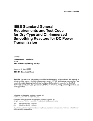
6.7.3 Connections
Typical connections for smoothing reactors are presented in Figure 1(a), Figure 1(b), and Figure 1(c). They
are bipolar, monopolar, and back-to-back. It should be noted that for a few back-to-back schemes, the
commutation inductance of the converter transformers has been designed to provide an equivalent smooth-
ing inductance; sufficient to provide the necessary smoothing of the dc current in the link without the need
of adding a separate smoothing reactor.
Figure 1a—Smoothing reactor connections HVDC transmission; bipolar configuration
18. IEEE
Std 1277-2000 IEEE TRIAL-USE GENERAL REQUIREMENTS AND TEST CODE FOR DRY-TYPE
12 Copyright © 2000 IEEE. All rights reserved.
Figure 1b—Smoothing reactor connections HVDC transmission;
monopolar configuration
Figure 1c—Smoothing reactor connections
back-to-back converter; sample configurations
IEEE STANDARD GENERAL REQUIREMENTS AND TEST CODE FOR DRY-TYPE
IEEE STANDARD GENERAL REQUIREMENTS AND TEST CODE FOR DRY-TYPE
19. IEEE
AND OIL-IMMERSED SMOOTHING REACTORS FOR DC POWER TRANSMISSION Std 1277-2000
Copyright © 2000 IEEE. All rights reserved. 13
7. Construction of oil-immersed smoothing reactors
7.1 Tank and tank components for oil-immersed smoothing reactors
7.1.1 Tank pressure requirements
Tank pressure, under rated conditions, for smoothing reactors shall not exceed 203 kPa absolute pressure
unless the requirements of applicable sections of the ANSI/ASME Boiler and Pressure Vessel Code (BPV),
1984 Edition, are met.
NOTE—203 kPa = 2 atmospheres
Maximum operating pressures (positive and negative) for which the smoothing reactor is designed shall be
indicated on the nameplate. The main tank, and any compartment attached thereto, that is subject to the
operating pressures shall be designed to withstand, without permanent deformation, a pressure 25% greater
than the maximum operating pressures, resulting from the system of oil preservation used.
NOTE—Individual designs may not necessarily reach the maximum pressures indicated in the definitions of oil-preser-
vation systems.
Tanks for all smoothing reactors shall be designed to withstand vacuum filling (essentially full vacuum) in
the field.
7.1.2 Cover construction
A bolted or welded main cover shall be provided.
7.1.3 Core ground
A single core ground shall be provided and shall be accessible without removing oil. Cable or bus bar is
utilized from ground pad to bushing.
7.1.4 Manholes
Manholes shall be provided in the cover. Manholes, if circular, shall have a minimum diameter of 460 mm.
If rectangular or oval, they shall have minimum dimensions of 360 mm × 460 mm.
7.1.5 Drain and filter valves
A combination drain and lower filter valve of the ball or globe type shall be located on the side of the tank.
This valve shall provide for drainage of the liquid to within 25 mm of the bottom of the tank. The drain
valve shall have a built-in 10 mm sampling device, which shall be located in the inside of the valve
between the main valve seat and the pipe plug. The device shall be supplied with a “5/16 in-32 male
thread” for the user’s connection and shall be equipped with a cap.
The size of the drain valve for smoothing reactors is typically 25 mm or 50 mm, as appropriate or
specified by the purchaser, and shall have NPT threads (in accordance with ANSI/ASME B1.20.1-1983
with nonferrous metallic pipe plug in open ends. Valves should not be located below any control cabinets.
If appropriate or specified by the purchaser, smoothing reactors shall have a 25 mm upper filter plug, or
cap, located above the maximum liquid level.
20. IEEE
Std 1277-2000 IEEE TRIAL-USE GENERAL REQUIREMENTS AND TEST CODE FOR DRY-TYPE
14 Copyright © 2000 IEEE. All rights reserved.
In all other cases or as specified by the purchaser, smoothing reactors shall have an upper filter valve of the
ball or globe type, located below the 25 °C liquid level. The size of the upper filter valve shall be 50 mm
and it shall have “2-in NPT threads” (in accordance with ANSI/ASME B1.20.1-1983 with nonferrous
metallic pipe plug in open ends.
7.1.6 Lifting, moving, and jacking facilities
7.1.6.1 Lifting facilities
Lugs for lifting the complete smoothing reactor shall be provided. The bearing surfaces of the lifting lugs
shall be free from sharp edges and each lifting lug shall be provided with a hole having a minimum diame-
ter of 21 mm for guying purposes. Lifting eyes shall be provided for lifting the cover only.
Adequate facilities shall be provided for lifting the core and coil assembly from the tank.
7.1.6.2 Moving facilities
The base of the smoothing reactor shall be designed to permit rolling or sliding in the direction of center
lines and provision shall be made for pulling the smoothing reactor in these directions.
The base shall be so designed that the center of gravity of the smoothing reactor, as normally prepared for
shipment, should not fall outside the base support members for a tilt of the base of 38 mm from the hori-
zontal, with or without oil in the smoothing reactor.
7.1.6.3 Jacking facilities
Jacking facilities shall be located near the corners of the tank.
Dimensions and clearances for jacking provisions shall be as shown in Figure 2.
7.1.7 Ground pads
Tank grounding provisions shall consist of two copper-faced steel pads or two stainless steel pads without
copper facing, each 50 mm × 90 mm with two holes horizontally spaced on 44.5 mm centers and drilled
and tapped for “1/2 in National Coarse Thread” (UNC) (as defined in ANSI/ASME B1.1-1989). The mini-
mum thickness of copper facing (if used) shall be 0.4 mm.
Thread protection for the ground pad shall be provided.
Ground pads shall be welded on the base or on the tank wall near the base, and shall be located diago-
nally opposite from each other so as not to interfere with the jacking facilities.
7.2 Oil preservation for oil-immersed smoothing reactors
7.2.1 Insulating liquids
Smoothing reactors shall be filled with a suitable insulating liquid such as mineral oil. New, unused min-
eral oil shall meet the requirements of ASTM D3487-1981. The appropriate quality of the oil, particularly
resistivity and particle count, that are required for initial commissioning and continued safe operation
should be specified by the manufacturer.
NOTE—IEEE Std C57.106-1991 provides information concerning the acceptance and maintenance of mineral oil,
including dielectric test breakdown criteria according to oil application, age, and test method.
IEEE STANDARD GENERAL REQUIREMENTS AND TEST CODE FOR DRY-TYPE
IEEE STANDARD GENERAL REQUIREMENTS AND TEST CODE FOR DRY-TYPE
21. IEEE
AND OIL-IMMERSED SMOOTHING REACTORS FOR DC POWER TRANSMISSION Std 1277-2000
Copyright © 2000 IEEE. All rights reserved. 15
7.2.2 Insulating liquid preservation
Smoothing reactors shall be equipped with an insulating liquid preservation system such as sealed-tank,
gas-oil seal, conservator, or conservator with diaphragm.
NOTE—The various insulating liquid (oil) preservation systems are described and defined in IEEE Std C57.12.80-1978.
NOTES:
1—Dimensions E, F, G, and H are free clearances.
2—Where required in the manufacturer’s standards designs, any dimensions may be in excess of those shown.
3—E applies to nonremovable coolers only.
4—Weight includes completely assembled reactor and fluid.
Weight 15 900 kg
or less
Weight 15 900–29 500 kg
Weight over
29 500 kg
A 89 mm A 127 mm A 457 mm
B 64 mm B 64 mm B 102 mm
E 686 mm E 686 mm E 508 mm
F 127 mm F 127 mm F 127 mm
G 76 mm G 76 mm G 76 mm
H 127 mm H 127 mm H 127 mm
Figure 2—Jacking provisions
22. IEEE
Std 1277-2000 IEEE TRIAL-USE GENERAL REQUIREMENTS AND TEST CODE FOR DRY-TYPE
16 Copyright © 2000 IEEE. All rights reserved.
7.3 Auxiliary equipment for oil-immersed smoothing reactors
7.3.1 Bushings
Smoothing reactors shall be equipped with bushings with an insulation level not less than that of the wind-
ing terminal to which they are connected, unless otherwise specified.
Bushings for use on oil-immersed smoothing reactors for HVDC application shall comply with
IEEE Std C57.19.03-1996.
Bushings for use in smoothing reactors shall have impulse and low-frequency insulation levels as listed in
IEEE Std C57.19.03-1996.
Smoothing reactors use specially designed dc bushings with design specific dimensions.
7.3.2 Bushing current transducers
7.3.2.1 Special bushing type dc current transducers
Special bushing-type dc current transducers, or provision for their addition in the future, shall be as speci-
fied. They are special devices not covered by standards.
7.3.2.2 Bushing-type current transducer dimensions
Bushing-type current transducers used with bushings having dimensions in accordance with
IEEE Std C57.19.03-1996, shall have an inside diameter adequate to accommodate the maximum D
dimensions for those bushings, as shown in the applicable tables in the dc bushing standard.
7.3.2.3 Output loads
All bushing current transducer output leads shall be brought to an outlet box.
7.3.2.4 Terminal blocks
Nonsplit terminal blocks shall be provided in a weather-resistant case of the nonsplit type located near the
smoothing reactor base for terminating alarm circuits specified in 7.3.4.
7.3.2.5 Bushing-type current transducer removed
Provisions shall be made for removing bushing-type current transducers from the tank without removing
the entire tank cover of the smoothing reactor in which they are to be used.
7.3.3 Surge arresters
The following types of construction are available for surge protection:
a) Provision only for the mounting of surge arresters.
b) Mounting complete with surge arresters.
c) Surge arrester ground pad consisting of a tank-grounding pad (in accordance with 7.1.7) mounted
near the top of the tank, may be specified for each set of arresters except that where the separation of
the arrester stack is such that individual pads for grounding each phase arrester represent better
design, individual ground pads may be supplied.
IEEE STANDARD GENERAL REQUIREMENTS AND TEST CODE FOR DRY-TYPE
IEEE STANDARD GENERAL REQUIREMENTS AND TEST CODE FOR DRY-TYPE
23. IEEE
AND OIL-IMMERSED SMOOTHING REACTORS FOR DC POWER TRANSMISSION Std 1277-2000
Copyright © 2000 IEEE. All rights reserved. 17
d) Many utilities prefer to run copper cable from the ground grid directly to the arrester. In such cases
provision to support the cable should be provided.
NOTE—Material for connecting surge arresters to live parts and to ground pads is not included.
7.3.4 Accessories
7.3.4.1 Liquid-level indicator
A liquid-level indicator shall be mounted so as to be readable at the level of the base. Dial markings shall
show 25 °C level and the minimum and maximum levels. The words liquid level shall be shown on the
face of the dial or on a suitable nameplate adjacent to the indicator.
7.3.4.2 Liquid-temperature indicator
A dial-type thermometer or thermocouple-based device shall be mounted on the side of the tank.
The temperature indicator must have resetable maximum temperature limits with corresponding contacts.
The thermometer shall be either a direct-stem mounted unit or a temperature sensing unit for remote eye-
level indication. Either unit shall be mounted in a closed well located at a suitable level to indicate the top-
oil temperature. For the dimensions of the well, see Figure 3.
The dial markings shall cover a minimum range of 0 °C to 120 °C. The words liquid temperature shall be
shown on the dial or on a suitable nameplate mounted adjacent to the indicator.
7.3.4.3 Temperature and liquid-level indicator alarm contacts
7.3.4.3.1 Alarm contacts
Nongrounded alarm contacts for liquid-level indicators and temperature indicators shall be dry, form-C
type and shall be suitable for interrupting:
a) 0.02 A dc inductive load
b) 0.20 A dc noninductive load
c) 2.5 A ac noninductive or inductive load
d) 250 V maximum in all cases.
Figure 3—Dimensions of thermometer well
24. IEEE
Std 1277-2000 IEEE TRIAL-USE GENERAL REQUIREMENTS AND TEST CODE FOR DRY-TYPE
18 Copyright © 2000 IEEE. All rights reserved.
The liquid-level indicator alarm contacts shall be nonadjustable and shall be set to close at the minimum
safe operating level of the liquid.
The liquid temperature indicator alarm contacts shall be adjustable over a range of 65 °C to 110 °C.
The winding-temperature indicator alarm contacts shall be adjustable over a range of 95 °C to 125 °C.
7.3.4.4 Pressure-vacuum gauge
A pressure-vacuum gauge shall be provided for smoothing reactors of the sealed-tank and gas-oil-sealed
construction.
7.3.4.5 Pressure-relief device
A pressure-relief device shall be provided on the smoothing reactor cover.
7.3.5 Controls power supply
7.3.5.1 Power-supply voltage
The power-supply voltage for the smoothing reactor controls shall be specified by the purchaser.
8. Tests
8.1 General
Unless otherwise specified, tests shall be made at the factory or in a test laboratory prior to delivery.
8.2 Routine, design, and other tests for smoothing reactors
Types of tests for oil-immersed smoothing reactors are listed in Table 1. Types of tests for dry-type
smoothing reactors are listed in Table 2.
8.2.1 Types of tests
8.2.2 Routine tests
Routine tests shall be made on all smoothing reactors of a multiple-unit order in accordance with the
requirements of Table 1 and Table 2, as applicable.
8.2.3 Design tests
Design tests, unless otherwise agreed between the purchaser and the manufacturer, shall be made on one
smoothing reactor (of a specific design) of a multiple-unit order, in accordance with the requirements of
Table 1 and Table 2, respectively. Test reports documenting the results of a previous test on a smoothing
reactor of a demonstrated similar design may be submitted for consideration by the purchaser in lieu of
performing a design test.
IEEE STANDARD GENERAL REQUIREMENTS AND TEST CODE FOR DRY-TYPE
IEEE STANDARD GENERAL REQUIREMENTS AND TEST CODE FOR DRY-TYPE
25. IEEE
AND OIL-IMMERSED SMOOTHING REACTORS FOR DC POWER TRANSMISSION Std 1277-2000
Copyright © 2000 IEEE. All rights reserved. 19
8.2.4 Other tests
Other tests as shown in Table 1 and Table 2 respectively, shall be performed on either one or all smooth-
ing reactors of a multiple-unit order as specified by the purchaser. Usually other tests are specified as
design tests. Test reports documenting the results of a previous test carried out on a smoothing reactor of a
demonstrated similar design may be submitted for consideration by the purchaser in lieu of performing an
other design test.
8.2.5 Test sequence
The listing of tests shown in Table 1 and Table 2 does not necessarily indicate the sequence in which the
tests shall be made. All tests are defined and shall be made in accordance with Clause 12.
8.2.6 Test sequence and other tests
If other tests are performed, their position in the sequence of tests should be determined by agreement
between the purchaser and the manufacturer. In most cases, position in the test sequence is not critical and
the test or verification can be performed or carried out as deemed appropriate, e.g., dc withstand voltage
test (pollution), short-circuit capability verification, seismic, etc.
8.2.7 Test equipment and methods
Test equipment and methods (procedures) described in this document are state-of-the-art at the time of writ-
ing. Newer equipment and procedures that give equivalent or improved tests should be used, if available.
26. IEEE
Std 1277-2000 IEEE TRIAL-USE GENERAL REQUIREMENTS AND TEST CODE FOR DRY-TYPE
20 Copyright © 2000 IEEE. All rights reserved.
Table 1—Routine, design, and other tests for oil-immersed smoothing reactors
Tests Routine Design Other
DC resistance o
Incremental inductance measurement o (Note 4)
Measurement of high-frequency impedance o
Loss measurement (dc and harmonics as applicable) o
Temperature-rise test o (Note 5)
DC power test o (Note 6)
Dielectric tests
Impulse tests
Full wave impulse o
Chopped wave impulse o
Switching impulse o (Note 9)
DC applied voltage (with partial discharge measurement) o
Polarity reversal (with partial discharge measurement) o
AC applied voltage (with partial discharge measurement) o
AC power test (with q-factor measurement) o
Insulation power factor o (Note 1)
Insulation resistance o (Note 1)
Audible sound level o (Note 2)
Short-circuit verification o (Note 3)
Capacitor discharge test o (Note 7)
Pressure leak test o
Seismic verification o (Note 8)
NOTES:
1—This test may not produce meaningful results if the smoothing reactor does not include an inner ground
shield or core.
2—Suitable allowance must be made and mutually agreed upon for the harmonic contribution in service.
Noise contributing elements of the reactor such as pumps and fans shall be operated as appropriate.
3—Calculations may be used based on a previous test of a reactor or model and strength of materials data in
lieu of the short-circuit withstand test.
4—The incremental inductance shall be measured from zero current to the maximum temporary dc
overcurrent (including the peak value of the rms sum of the harmonic currents).
5—The temperature-rise test may not be performed if the manufacturer demonstrates to the purchaser that
temperature-rise test results on an equivalent unit are available.
6—The dc power test is a quality assurance test; the purpose of which is to detect broken conductors or bad
connections. This test can be made part of the oil-particle filtration that is normally done prior to performing
dielectric tests. The oil filtration is carried out by applying a dc current for several hours to the smoothing
reactor. However, it is recommended that the issue be dealt with by resistance or continuity checks during
manufacturing; and that such tests be part of an inspection and test plan and the manufacturer should not
rely solely on a final test program.
7—This other test, when required, should be carried out at a frequency on the order of 300–900 Hz. Its
purpose is to simulate operating conditions as described in Annex A. This test demonstrates voltage
withstand capability.
8—Seismic qualification may be done by analytical methods. Refer to IEEE Std 693-1996.
9—The switching impulse test across the windings of an oil-immersed smoothing reactor is a routine test. In
general, it is difficult to obtain the required waveshape due to the kilojoule limitations of existing impulse
generators. The switching impulse test to ground is a routine test.
IEEE STANDARD GENERAL REQUIREMENTS AND TEST CODE FOR DRY-TYPE
IEEE STANDARD GENERAL REQUIREMENTS AND TEST CODE FOR DRY-TYPE
27. IEEE
AND OIL-IMMERSED SMOOTHING REACTORS FOR DC POWER TRANSMISSION Std 1277-2000
Copyright © 2000 IEEE. All rights reserved. 21
Table 2—Routine, design, and other tests for dry-type smoothing reactors
Tests Routing Design Other
DC resistance o (Note 1)
Inductance o (Note 1)
Measurement of high frequency impedance o
Loss measurement (dc and harmonics as applicable) o (Note 1)
Temperature-rise test o (Note 8)
DC power test o (Note 5)
Dielectric tests
Impulse tests
Full wave impulse o (Note 10)
Chopped wave impulse o
Switching impulse o (Note 9) o (Note 9)
AC power test o
DC wet voltage withstand test o (Note 2)
DC pollution test on insulators o (Note 6)
RIV test o
Audible sound level o
Short-circuit verification o (Note 3)
Capacitor discharge test o (Note 7)
Seismic verification o (Note 4)
NOTES:
1—The routine test sequence for dry-type air-core smoothing reactors consists of dc resistance, inductance, loss
measurement, dielectric, dc resistance (repeated), inductance (repeated), and loss measurement (repeated). For the
order of dielectric tests refer to 12.6.2.
2—This test may be waived for smoothing reactors installed in the neutral bus, depending on system design
requirements, or if the smoothing reactor is to be installed indoors.
3—Calculations may be used, based on a previous test of a reactor or model and strength of materials data in lieu of
the short-circuit withstand test.
4—Seismic qualification may be done by analytical methods. Refer to IEEE Std 693-1996.
5—The dc power test is a quality assurance test, the purpose of which is to detect broken conductors or bad
connections.
6—This other test, when required, is to demonstrate performance of the support insulators only, under conditions of
pollution. It is a wet dc withstand test with contamination levels as specified by the purchaser. It is a test to be
carried out on at least one of the support insulators.
7—This other test, when required, should be carried out at a frequency on the order of 300–900 Hz. Its purpose is to
simulate operating conditions as described in Annex A. This test demonstrates voltage withstand capability.
8—The temperature-rise test may not be performed if the manufacturer demonstrates to the purchaser that
temperature-rise test results on an equivalent unit are applicable.
9—The switching impulse test is a design test when performed across the support insulators to ground.It is an other
test when performed across the winding of a dry-type air-core smoothing reactor since it is not possible to obtain the
desired waveshape due to the kilojoule limitations of existing impulse generators.
10—If a dry-type air-core smoothing reactor is supplied with a pollution or sound mitigation shield (enclosure), the
impulse-design test shall be carried out with the mitigation measures installed.
28. IEEE
Std 1277-2000 IEEE TRIAL-USE GENERAL REQUIREMENTS AND TEST CODE FOR DRY-TYPE
22 Copyright © 2000 IEEE. All rights reserved.
9. Losses and inductance
9.1 Losses
9.1.1 Total losses
The losses of a dc smoothing reactor are those losses that are incident to the carrying of a current. They
include the following:
a) The resistance loss in the winding due to the dc load current constitute the primary loss in a dc
smoothing reactor.
b) Harmonics or ripple currents produce both resistive and eddy-current losses in the winding. These
losses are significantly smaller than the dc losses.
c) Losses caused by circulating currents in parallel windings.
d) Stray losses caused by magnetic flux in other metallic parts of the reactor are typically a very small
percentage of total losses, due to the low magnitude of the ripple current.
e) For dry-type smoothing reactors losses include those occurring in the support structure. Due to the
low magnitude of the ripple current, the stray losses in the support structure are usually a small per-
centage of total losses.
f) For oil-immersed smoothing reactors core losses are typically 1.0–1.5% of total losses. In a few rare
cases, due to the magnitude of the harmonics, the core losses have been as high as 2% of total losses.
g) For oil-immersed smoothing reactors, power required for cooling fans, oil pumps, space heaters, and
other ancillary equipment is not included in the total loss. When specified or requested by the pur-
chaser, loss data on such ancillary equipment shall be furnished.
9.1.2 Tolerance on losses
A tolerance on losses is utilized for two purposes. One is for commercial evaluation and the other is to
provide the basis of a quality check.
9.1.2.1 Tolerance on losses for commercial evaluation
As energy costs increase, losses become a more significant component of total operating costs and as such
may be capitalized by the purchaser. Therefore, compliance to guaranteed losses becomes part of the com-
mercial contract. A tolerance on losses, to account for measurement tolerances, etc., may be part of the
contractual agreement. If the measured losses corrected to reference temperature exceed the guaranteed
loss by more than 10% it may be indicative of a design issue.
Additionally, the contract may specify such guarantee criteria as maximum loss per unit, average loss for
all units, total package losses, etc. In any case, this is purely a commercial matter between the purchaser
and the manufacturer.
It should be stressed that if a unit exceeds guaranteed loss, aside from the commercial implications which
are a matter between the manufacturer and the purchaser, it is essential to demonstrate that temperature-
rise limits, for the insulation systems employed, are not exceeded.
IEEE STANDARD GENERAL REQUIREMENTS AND TEST CODE FOR DRY-TYPE
IEEE STANDARD GENERAL REQUIREMENTS AND TEST CODE FOR DRY-TYPE
29. IEEE
AND OIL-IMMERSED SMOOTHING REACTORS FOR DC POWER TRANSMISSION Std 1277-2000
Copyright © 2000 IEEE. All rights reserved. 23
9.1.2.2 Tolerance on losses as the basis of a quality check
The losses, as defined in the specification, on any reactor shall not differ from the average loss of all units
of the same design by more than 6%. The average loss shall be calculated by using the measured losses on
each individual unit.
If one of the units exceeds this tolerance, the manufacturer shall initiate an investigation in order to find
the cause of this deviation. In order for acceptance to be considered, the manufacturer shall demonstrate to
the purchaser, by either calculation and/or test, that the deviation will not impair the ability of the unit to
meet the other requirements of this standard, particularly the temperature-rise limits.
9.2 Inductance
9.2.1 Tolerances on inductance
9.2.1.1 Tolerance and current
Tolerances on inductance apply over a current range from zero to full-rated current. The minimum induc-
tance at short circuit must be specified.
9.2.1.2 Tolerance percentage
The inductance of a smoothing reactor shall have a standard tolerance of ±7% or, if specified, shall not
vary from the specified value set by the purchaser by more than a specified plus or minus percent. The tol-
erance on inductance may impact the design of the dc filters.
10.Temperature rise and loading conditions
10.1 Temperature-rise limits and loading conductors
Temperature-rise limits for HVDC smoothing reactors are presented in Table 3.
Since smoothing reactors on HVDC schemes (transmission or back-to-back) are almost always loaded at
or near nameplate rating, the maximum hottest-spot temperature-rise limits are selected to be conserva-
tive. The maximum hot-spot temperature-rise limits in Table 3 are based on continuous operation in a
30 °C daily average ambient with a 40 °C maximum.
If the actual annual ambient temperature is lower, or the smoothing reactor sees lower than nameplate
loads for extended periods of time, then consideration can be given to increasing the allowable hottest-spot
winding temperature-rise limits.
Conversely, many HVDC schemes have overload conditions specified as part of their standard operating
mode (e.g., seasonal overloads, monopolar operation). HVDC smoothing reactors are directly impacted by
such requirements and, hence, the maximum hottest-spot temperature rise should either reflect the worst-
case service duty or the hottest-spot temperature rise at normal nameplate current rating should be adjusted
accordingly.
Total hot-spot temperature defines the rate of aging of insulation and in conjunction with time at tempera-
ture determines service life. Therefore, care should be taken in selecting insulation materials and in select-
ing (design objectives) total operating hot-spot temperature for full load rated current, short-time
overloads, and continuous overloads.
30. IEEE
Std 1277-2000 IEEE TRIAL-USE GENERAL REQUIREMENTS AND TEST CODE FOR DRY-TYPE
24 Copyright © 2000 IEEE. All rights reserved.
10.2 Temperature of metalic parts in contact with insulation
Metallic parts in contact with or adjacent to the insulation system shall not attain a temperature in excess
of that allowed for the hottest spot of the windings adjacent to that insulation.
10.3 Temperature of other metalic parts
Metallic parts other than those covered in 10.2 above shall not attain excessive temperature rises. In the
case of oil-immersed smoothing reactors, this includes magnetic shields, tank walls, etc. Operating temper-
atures should be consistent with the capabilities of the oil/paper insulation system, typically 120 °C under
normal operating conditions. In the case of dry-type air-core smoothing reactors, auxiliary metallic compo-
nents include support structure elements such as insulator caps, spring/damping systems (for seismic appli-
cation), insulator mounting brackets, bracing elements, etc. Allowable in-service operating temperatures
should be consistent with the capabilities of the materials employed.
10.4 Temperature rise of insulating liquid
The temperature rise of the insulating liquid in an oil-immersed smoothing reactor should not exceed
65 °C rise when measured near the top of the tank.
10.5 Temperature rise of terminals
The temperature rise of terminals should be lower than 50 °C for bare aluminum or copper, 65 °C for tin-
plated, and 75 °C for silver- or nickel-plated. Higher temperatures are allowable, depending on the use of
various termination methodologies and contact aids.
Table 3—Limits of temperature rise for HVDC smoothing reactors
Insulation temperature class
Average
winding temperature rise
by resistance (°C)
Hottest-spot
winding temperature rise
(°C)
Type of smoothing reactor
Oil-immersed 65 80
Dry-type
(A) 105 55 65
(B) 130 80 90
(F) 155 100 115
(H) 180 125 140
(C) 220 150 180
NOTES:
1—The insulation temperature classes in Table 3 are selected in accordance with the preferred
temperature index for insulation materials as defined in ANSI/IEEE Std 1-1986.
2—The assignment of the reactors’ insulation system to a certain temperature class shall be
proven by experience or testing.
3—The average temperature rise and hot-spot temperature rise are upper limits and neither are to
be exceeded.
4—The difference between the hot-spot rise and the average rise is not intended to be an indica-
tion of hot-spot allowance. Hot-spot allowance is very much design related and no simple rule can
account for it, especially with the wide variety of custom designs available today.
IEEE STANDARD GENERAL REQUIREMENTS AND TEST CODE FOR DRY-TYPE
IEEE STANDARD GENERAL REQUIREMENTS AND TEST CODE FOR DRY-TYPE
31. IEEE
AND OIL-IMMERSED SMOOTHING REACTORS FOR DC POWER TRANSMISSION Std 1277-2000
Copyright © 2000 IEEE. All rights reserved. 25
11. Dielectric tests and insulation levels
11.1 Impulse tests
11.1.1 General
In order to ensure the best possible diagnostics, all design and routine impulse tests shall be carried out
using a digital impulse test system—the transfer function calculation is one obvious benefit. Smoothing
reactors for HVDC application are critical pieces of equipment and the best available test technology must
be used.
11.1.2 Full-wave impulse tests
An impulse test level shall be specified for each terminal to ground and across the winding. If chopped-
wave impulse tests are required, impulse tests shall include reduced full-wave, chopped-wave, and full-
wave tests.
11.1.3 Switching impulse tests
When required, the winding shall be subjected to switching impulse tests to ground. These should be
performed with both ends of the tested winding connected together. The test level to ground shall be
specified by the purchaser. This is applicable to oil-immersed and dry-type smoothing reactors.
If a switching impulse withstand test is specified across the winding of an oil-immersed or dry-type
smoothing reactor, a switching impulse test should be performed across the winding—from both terminals
with the other terminal grounded. For low inductance smoothing reactors, the energy available from the
impulse generator may not be sufficient to produce the required wave shape. In such cases, the manufac-
turer should advise the purchaser at the bid stage.
11.1.4 Chopped-wave test
In the case of oil-immersed or dry-type air-core smoothing reactors, the chopped-wave test, when required,
is a test mainly of the winding turns insulation.
11.2 DC voltage tests
11.2.1 DC voltage tests with partial discharge measurements for oil-immersed smoothing
reactors
These tests are carried out by applying a voltage of positive polarity to the terminals of the winding of the
smoothing reactor for a duration of 2 h. The test voltage is given by
(1)
11.2.2 DC voltage tests for dry-type smoothing reactors
This test is applied to the insulators of the smoothing reactor. The dc test voltage applied for 1 h under wet
conditions is given by
(2)
Edc 1.5 EdcSystem
=
Edc 1.5 EdcSystem
=
32. IEEE
Std 1277-2000 IEEE TRIAL-USE GENERAL REQUIREMENTS AND TEST CODE FOR DRY-TYPE
26 Copyright © 2000 IEEE. All rights reserved.
11.3 DC polarity-reversal test with partial discharge measurements for oil-
immersed smoothing reactors
This test shall be applied to the terminals of the winding(s) connected together. The test level for smooth-
ing reactors is
(3)
A double reversal test shall be used as shown in Figure 4. The duration of the first two voltages is 90 min
each, while the duration of the last voltage is 45 min. The reversal should be accomplished within 2 min
maximum.
11.4 Low-frequency voltage tests on line terminals
11.4.1 AC applied voltage test to ground with partial discharge measurements for oil-
immersed smoothing reactors
For oil-immersed smoothing reactors, winding terminals shall receive an ac applied voltage test to ground.
The rationale for this test can be found in the CIGRÉ paper [B14]. The duration of the test shall be
60 min, and the test level is given by
(4)
11.4.1.1 AC power test between terminals with Q-factor measurements
This is an ac power test (across the winding) with Q-factor measurement. The purpose is to verify wind-
ing insulation integrity after all dielectric tests are completed.
NOTE—The Q-factor measurement is not for the purpose of loss guarantees. For loss-guarantee purposes the harmonic
losses will be calculated.
The frequency of the power supply shall be between power frequency (60 Hz, or 50 Hz) and 1000 Hz. The
test voltage shall be at 2 times the maximum specified continuous harmonic voltage drop. The duration of
the test shall be 5 min. The Q-factor or losses at test supply frequency will be measured at the beginning
of the dielectric test sequence and these values will be compared to those measured during the ac power
test.
EPR 1.25 EdcSystem
=
Figure 4—Double polarity reversal
EacApplied
1.5EdcSystem
2
---------------------------
-
=
IEEE STANDARD GENERAL REQUIREMENTS AND TEST CODE FOR DRY-TYPE
IEEE STANDARD GENERAL REQUIREMENTS AND TEST CODE FOR DRY-TYPE
33. IEEE
AND OIL-IMMERSED SMOOTHING REACTORS FOR DC POWER TRANSMISSION Std 1277-2000
Copyright © 2000 IEEE. All rights reserved. 27
12. Test code
12.1 General
This clause prescribes methods for performing the tests specified in Clause 8. Although the figures of this
standard show conventional meters, adequate digital readout measuring devices and digital sampling tech-
niques with computer calculations are considered as satisfactory alternatives and may actually be pre-
ferred as mentioned in various places in the text.
12.2 Resistance measurements
Resistance measurements are of fundamental importance for the following purposes:
a) Calculation of I2R component of conductor losses
b) Calculation of winding temperature at the end of a temperature test
c) As a basis for assessing possible damage in the field
12.2.1 Determination of cold temperature
The cold temperature of the winding shall be determined as accurately as possible when measuring the
cold resistance. The following precautions should be observed.
12.2.1.1 General
The reactor shall be located in a room free of drafts, with a relatively constant temperature for a period of
at least 5 times the thermal time constant before cold resistance readings are taken.
12.2.1.2 Oil-immersed smoothing reactors: windings immersed in insulating liquid
The temperature of the winding shall be assumed to be the same as the mean value of the top and bottom
temperatures of the insulating liquid, provided
a) The winding has been under insulating liquid with no excitation and with no current in the winding
for a time of 3 h to 8 h (depending on the size of the smoothing reactor) before the cold resistance is
measured.
b) The temperature of the insulating liquid has stabilized, and the difference between the top and bot-
tom temperatures does not exceed 5 °C.
12.2.1.3 Dry-type air-core smoothing reactors
The temperature of the windings shall be determined by placing thermometers, thermocouples, or thermal
sensors along the length and around the circumference of the outermost winding group. The average of the
recorded temperature shall be taken as the winding temperature. Good contact can be assured by using a
material such as silicone to hold the end of the thermometer or thermocouple in place.
12.2.2 Conversion of cold resistance measurements
Cold winding resistance measurements are normally converted to a standard reference temperature equal
to the rated average winding temperature rise plus 20 °C. In addition, it may be necessary to convert the
resistance measurements to the temperature at which the impedance loss measurements were made. The
conversions are accomplished by the following formula
34. IEEE
Std 1277-2000 IEEE TRIAL-USE GENERAL REQUIREMENTS AND TEST CODE FOR DRY-TYPE
28 Copyright © 2000 IEEE. All rights reserved.
(5)
where
Rs is resistance at desired temperature, Ts,
Rm is measured resistance,
Ts is desired reference temperature,
Tm is temperature at which resistance was measured,
Tk = 234.5 °C for copper
= 225 °C for aluminum.
NOTE—The value of Tk may be as high as 230 for alloyed aluminum. In general, for any other type of conductor mate-
rial the appropriate constant of Tk shall be used. In such cases, the manufacturer shall demonstrate by test or calculations,
the validity of the constant Tk .
12.2.3 Methods for measuring resistance
Bridge or drop-of-potential (volt-ammeter) methods may be used for measuring dc resistance. If a voltme-
ter-ammeter method is employed, the test current should be such as to not produce a rise in temperature of
the winding; less than 15% of rated current. Digital voltmeters and digital ammeters of appropriate accu-
racy are commonly used in connection with temperature-rise determinations.
12.2.3.1 Readings and calculation of resistance
Measurement is made with dc, and simultaneous readings of current and voltage are taken using the con-
nections of Figure 5. The required resistance is calculated from the readings in accordance with Ohm’s
Law. A battery or filtered rectifier will generally be more satisfactory as a dc source than a commutating
dc machine. The latter may cause the voltmeter pointer to vibrate because of voltage ripple.
12.2.3.2 Errors of observation
To minimize errors of observation
a) The measuring instruments shall have such ranges as will give reasonably large deflection.
b) For all iron-core oil-immersed smoothing reactors, the polarity of the core magnetization shall be
kept constant during all resistance readings.
NOTE—A reversal in magnetization of the core can change the time constant and result in erroneous readings.
12.2.3.3 Voltmeter leads
The voltmeter leads shall be independent of the current leads and shall be connected as closely as possible
to the terminals of the winding to be measured. This is to avoid including in the readings the resistances of
current-carrying leads and their contacts and of extra lengths of leads (Figure 5).
To protect the voltmeter from injury by off-scale deflections, the voltmeter should be disconnected from
the circuit or shunted by a bypass switch before switching the current off.
12.2.3.4 Steady-state conditions
Readings shall not be taken until after the current and voltage have reached steady-state values.
Rs Rm
Ts Tk
+
Tm Tk
+
------------------
-
=
IEEE STANDARD GENERAL REQUIREMENTS AND TEST CODE FOR DRY-TYPE
IEEE STANDARD GENERAL REQUIREMENTS AND TEST CODE FOR DRY-TYPE
35. IEEE
AND OIL-IMMERSED SMOOTHING REACTORS FOR DC POWER TRANSMISSION Std 1277-2000
Copyright © 2000 IEEE. All rights reserved. 29
When measuring the cold resistance, prior to making a temperature-rise test, note the time required for the
readings to become constant. The period thereby determined should be allowed to elapse before taking the
first reading when the final winding hot resistance measurements are being made.
In general, the winding will exhibit a long dc time constant. To reduce the time required for the current to
reach its steady-state value, a noninductive external resistor should be added in series with the dc source.
The resistance should be large compared to the inductance of the winding. It will then be necessary to
increase the source voltage to compensate for the voltage drop in the series resistor.
12.2.3.5 Readings and values of current
Readings shall be taken with not less than four values of current. The average of the resistances calculated
from these measurements shall be considered to be the resistance of the winding.
The current used shall not exceed 15% of the rated current of the winding whose resistance is to be mea-
sured. Larger values may cause inaccuracy by heating the winding and thereby changing its temperature
and resistance.
12.3 Losses and impedance
12.3.1 Impedance test
The impedance voltage comprises an effective resistance component corresponding to the impedance
losses, and a reactance component corresponding to the flux linkages of the winding.
12.3.2 Measurement of incremental inductance for oil-immersed smoothing reactors
Due to iron-saturation effects, the inductance of oil-immersed smoothing reactors is not linear. Therefore,
the incremental inductance shall be determined as a function of the dc from zero up to the specified maxi-
mum overload current plus the peak value of the rms sum of the harmonic currents.
The test shall be performed by registering the current decay in the short-circuited smoothing reactor. The
reactor shall be charged up with a current from a rectifier to a value of current equal to the maximum over-
load current or higher, if necessary, to ensure the core material saturation characteristic beyond the knee
point is accounted for. This will ensure that the inductance at any current value, including short circuit, can
be determined. The reactor is then short-circuited through a current shunt and the rectified voltage source
is disconnected.
Figure 5—Connections for the voltmeter-ammeter method of resistance measurement
36. IEEE
Std 1277-2000 IEEE TRIAL-USE GENERAL REQUIREMENTS AND TEST CODE FOR DRY-TYPE
30 Copyright © 2000 IEEE. All rights reserved.
The current decay through the reactor is registered in sufficient detail for several seconds, in order to pro-
vide adequate information from which the curve of incremental inductance vs. dc can be derived. At every
instant the following relation holds true
(6)
where
R is the resistance of the discharge circuit (reactor, connecting leads, and measurement shunt).
The circuit resistance shall be kept as low as possible and should be measured before and after the test in
order to take into account the effect of temperature rise on the discharge circuit components. The mean
value of the resistance measured before and after the test shall be used as the circuit-resistance value. The
slope of the current curve at every point represents the inverse value of the incremental inductance.
The incremental inductance at dc currents close to zero may be determined accurately with ac excitation at
relatively low voltage.
12.3.3 Measurement of inductance of dry-type smoothing reactors
The inductance shall be measured at 50 or 60 Hz at any convenient current provided the measurement is
disturbance free. The test shall be repeated after the dielectric test. The values should be consistent within
measurement accuracy and repeatability.
12.3.4 Measurement of harmonic impedance of dry-type smoothing reactors
It may be required that the impedance and especially the Q-factor of a dry-type SMR be measured at the
12th and/or the 24th harmonics. The measurements can provide information for evaluation of the total
losses and may be required for systems modeling.
12.3.5 Losses
12.3.5.1 Measurement of losses of dry-type air-core smoothing reactors
12.3.5.1.1 Total losses of dry-type smoothing reactors
For dry-type HVDC smoothing reactors, the total losses shall be calculated at reference temperature as the
sum of the losses at rated dc current and losses at all harmonic currents defined in the harmonic current
spectrum for rated operating conditions.
12.3.5.1.2 Measurement methodology for dry-type air-core smoothing reactors
The impedance of a dry-type air-core smoothing reactor remains constant with current and therefore losses
may be measured at any value of current and corrected to rated harmonic current. (For temperature correc-
tion of the impedance loss, refer to 12.3.7.)
(7)
L di dt
⁄
( )
– Ri
=
Pr
Ir
Im
----
-
2
Ps
=
IEEE STANDARD GENERAL REQUIREMENTS AND TEST CODE FOR DRY-TYPE
IEEE STANDARD GENERAL REQUIREMENTS AND TEST CODE FOR DRY-TYPE
37. IEEE
AND OIL-IMMERSED SMOOTHING REACTORS FOR DC POWER TRANSMISSION Std 1277-2000
Copyright © 2000 IEEE. All rights reserved. 31
where
Pr is losses at rated current,
Ir is rated current,
Im is current in the reactor when losses were measured,
Ps is losses at reference temperature, Ts, and measured current, Im.
12.3.5.1.3 Bridge methods
Bridge methods allow the simultaneous measurement of reactance (inductance) and effective resistance.
The impedance is calculated by the following equation:
(8)
where
Zh is impedance at harmonic frequency,
Rh is resistance component of the impedance at harmonic frequency,
Xh is reactance component of the impedance at harmonic frequency.
If a wattmeter is used to determine losses, then impedance can be calculated by measuring simultaneous
current and voltage and dividing the voltage by the current.
Resistance and reactance components of the impedance voltage are determined
(9)
(10)
where
Er is resistance voltage component, in-phase component,
Pa is watts measured in impedance test of winding carrying current,
I is current in winding on which voltage is impressed (A),
Ex is reactance voltage component, quadrature component,
Ez is impedance voltage of winding carrying current.
12.3.5.1.4 Q-factor at main ripple harmonic frequencies
When requested by the purchaser, the Q-factor at the major ripple harmonic frequencies should be mea-
sured and reported.
12.3.5.2 Measurement of total losses of oil-immersed smoothing reactors
For oil-immersed smoothing reactors, the losses consist of four components
a) Idc
2
Rdc losses in windings and leads
b) Eddy losses and resistive losses in windings due to harmonic currents
Zh Rh
2
Xh
2
+
=
Er
Pa
I
-----
-
=
Ex EZ
2
Er
2
–
( )
=
38. IEEE
Std 1277-2000 IEEE TRIAL-USE GENERAL REQUIREMENTS AND TEST CODE FOR DRY-TYPE
32 Copyright © 2000 IEEE. All rights reserved.
c) Stray losses in enclosure or tank due to harmonic currents
d) Core losses
The total harmonic losses are the sum of the losses as described in items b)–d). The individual harmonic
loss components described in items b)–d) cannot be separated by measurement. Therefore, a value for the
core losses provided by the manufacturer should be used in the loss calculations for oil-immersed smooth-
ing reactors as presented in 12.3.8.
NOTE—For a typical oil-immersed smoothing reactor, the Idc
2Rdc losses represent approximately 95% of the total
losses while the harmonic losses (including the core losses which account for about 50% of the harmonic losses) repre-
sent the remainder. Therefore, any resultant inaccuracy, due to using a core-loss figure that is not based on measurement,
is low. For instance, an error of 20% in calculating core losses results only in an error of 0.5% for the total losses.
12.3.6 Conversion of dc losses to reference temperature
The losses at rated dc current are corrected to reference temperature by converting the dc resistance to the
reference temperature using Equation (5) and then calculating the I2
R loss using the rated dc current.
12.3.7 Conversion of resistance and stray losses to reference temperature
The I2
R component of the impedance loss at any harmonic frequency increases with the temperature while
the stray-loss component diminishes with temperature. Consequently, when it is desired to convert the
impedance losses from one temperature to another, the two components of the impedance loss are con-
verted separately. Thus
(11a)
where
(11b)
Tk = 234.5 °C for copper,
= 225 °C for aluminum.
Pr and Ps are the resistance and stray losses, respectively, at the specified temperature Θ °C and Prm and
Psm are the measured resistance and stray losses at temperature Θ' °C.
12.3.8 Loss calculations for oil-immersed smoothing reactors
The procedure for determining losses of an oil-immersed smoothing reactor is as follows:
a) Measure all winding resistances
b) Calculate Idc
2R loss (Pdc) using rated dc current and correct loss value to the standard reference tem-
perature of 85 °C by using Equation (11a).
c) Measure harmonic losses for each specified harmonic current. Calculate the associated Ih
2Rdc loss
and stray losses. This measurement shall be carried out at zero dc current; harmonic current only.
The value for the core loss provided by the manufacturer shall be deducted from this measurement.
Correct the measured losses to the standard reference temperature of 85 °C by using Equation (11a)
and Equation (11b).
Pr Prm
Tk θ
+
Tk θ'
+
---------------
-
=
PS Psm
Tk θ'
+
Tk θ
+
---------------
-
=
IEEE STANDARD GENERAL REQUIREMENTS AND TEST CODE FOR DRY-TYPE
IEEE STANDARD GENERAL REQUIREMENTS AND TEST CODE FOR DRY-TYPE
39. IEEE
AND OIL-IMMERSED SMOOTHING REACTORS FOR DC POWER TRANSMISSION Std 1277-2000
Copyright © 2000 IEEE. All rights reserved. 33
d) Correct the measured harmonic losses at each harmonic frequency for the specified harmonic cur-
rent amplitude (Ih) by using Equation (7).
e) The total losses at 85 °C is calculated
(12)
where
PLLT is total load losses at T = 85 °C,
Ph is harmonic losses (including core losses) at harmonic frequency, h, and corrected to 85 °C.
12.4 Temperature-rise test
12.4.1 Loading for temperature-rise test
The smoothing reactor shall be tested under loading conditions that will give losses equal to or higher than
those obtained at rated current, including rated harmonic currents, in the winding. Since it is usually not
possible to apply both dc current and harmonic current simultaneously, the test shall be made with dc cur-
rent that produces losses in the reactor winding equivalent to the total losses calculated in Equation (7) in
the case of dry-type air-core smoothing reactors and Equation (12) in the case of oil-immersed smoothing
reactors.
The thermal equivalent dc current for the test shall be calculated
(13)
where
Itest is dc test current,
Idc is rated dc current,
Phtot is sum of harmonic current losses (resistive plus eddy),
Rdc is winding dc resistance corrected to reference temperature.
If laboratory power is not sufficient or power control adjustment is not fine enough to carry out a test at
full current, testing at a current level down to 90% of Itest is permissible. The measured temperature rise
shall be corrected using Equation (17).
12.4.2 Temperature-rise test—general (common) test procedures
12.4.2.1 Assembly for test
Reactors shall be completely assembled. For dry-type air-core smoothing reactors, the temperature-rise test
need not be performed on the contract support structure (see 12.4.4.8).
12.4.2.2 Temperature of surrounding air
The temperature of the surrounding air, ambient temperature, shall be determined by at least three thermo-
couples, or thermometers, spaced uniformly around the reactors under test. They should be located at
about one half of the height of the reactor, and at a distance of 1–2 m from the reactor. They should be
protected from drafts and abnormal heating.
PLLT Pdc ΣPh
+
=
Itest Idc
2
RDC Phtot
+
( ) RDC
⁄
=