SlideShare a Scribd company logo
1 of 12
Download to read offline
P/N 003-377
Issue 7
Standard Recommended Procedure 003-377 | Issue 7 | June 2017 | Page 1 of 12
Single-Shelf High-Density Frame
Housing Installation
related literature | Search www.corning.com/opcomm. Click on “Resources.”
HD12430243C-
W4SP1A_NAFTA_
AEN
Product Specifications, High-Density Frame Housing, Stubbed
Table of Contents
1. General. . . . . . . . . . . . . . . . . . . . . . . . . . . . . . . . . . . . . . . . . . . . . . . . . . . . . . . . . . . . . . . . . . . . . . . . . . . . . . . . . . . . . . . . . . . . . . . . . . . . . . . . . . . 1
2. Components. . . . . . . . . . . . . . . . . . . . . . . . . . . . . . . . . . . . . . . . . . . . . . . . . . . . . . . . . . . . . . . . . . . . . . . . . . . . . . . . . . . . . . . . . . . . . . . . . . . . .2
3. Tools and Equipment. . . . . . . . . . . . . . . . . . . . . . . . . . . . . . . . . . . . . . . . . . . . . . . . . . . . . . . . . . . . . . . . . . . . . . . . . . . . . . . . . . . . . . . . . . . . 2
4. Precautions. . . . . . . . . . . . . . . . . . . . . . . . . . . . . . . . . . . . . . . . . . . . . . . . . . . . . . . . . . . . . . . . . . . . . . . . . . . . . . . . . . . . . . . . . . . . . . . . . . . . . . 2
5. Stubbed Unit Unpacking. . . . . . . . . . . . . . . . . . . . . . . . . . . . . . . . . . . . . . . . . . . . . . . . . . . . . . . . . . . . . . . . . . . . . . . . . . . . . . . . . . . . . . . . .  3
6. Rack Mounting. . . . . . . . . . . . . . . . . . . . . . . . . . . . . . . . . . . . . . . . . . . . . . . . . . . . . . . . . . . . . . . . . . . . . . . . . . . . . . . . . . . . . . . . . . . . . . . . . .  3
7. Cable Preparation . . . . . . . . . . . . . . . . . . . . . . . . . . . . . . . . . . . . . . . . . . . . . . . . . . . . . . . . . . . . . . . . . . . . . . . . . . . . . . . . . . . . . . . . . . . . . . . 4
8. Cable Grounding and Strain-relief. . . . . . . . . . . . . . . . . . . . . . . . . . . . . . . . . . . . . . . . . . . . . . . . . . . . . . . . . . . . . . . . . . . . . . . . . . . . . . . . . 5
8.1 Ground Cable with Metallic Central Member . . . . . . . . . . . . . . . . . . . . . . . . . . . . . . . . . . . . . . . . . . . . . . . . . . . . . . . . . . . . . . 5
8.2 Ground Armored Cable (Metallic Cable Sheath) . . . . . . . . . . . . . . . . . . . . . . . . . . . . . . . . . . . . . . . . . . . . . . . . . . . . . . . . . . . . 5
8.3 Strain-Relieve Cable. . . . . . . . . . . . . . . . . . . . . . . . . . . . . . . . . . . . . . . . . . . . . . . . . . . . . . . . . . . . . . . . . . . . . . . . . . . . . . . . . . . . . . . 6
9. Fiber Routing. . . . . . . . . . . . . . . . . . . . . . . . . . . . . . . . . . . . . . . . . . . . . . . . . . . . . . . . . . . . . . . . . . . . . . . . . . . . . . . . . . . . . . . . . . . . . . . . . . . . . 7
10. Splicing. . . . . . . . . . . . . . . . . . . . . . . . . . . . . . . . . . . . . . . . . . . . . . . . . . . . . . . . . . . . . . . . . . . . . . . . . . . . . . . . . . . . . . . . . . . . . . . . . . . . . . . . . . 9
11. Connector Care. . . . . . . . . . . . . . . . . . . . . . . . . . . . . . . . . . . . . . . . . . . . . . . . . . . . . . . . . . . . . . . . . . . . . . . . . . . . . . . . . . . . . . . . . . . . . . . . . . 11
12. Jumper Installation. . . . . . . . . . . . . . . . . . . . . . . . . . . . . . . . . . . . . . . . . . . . . . . . . . . . . . . . . . . . . . . . . . . . . . . . . . . . . . . . . . . . . . . . . . . . . . 11
13. Attenuators. . . . . . . . . . . . . . . . . . . . . . . . . . . . . . . . . . . . . . . . . . . . . . . . . . . . . . . . . . . . . . . . . . . . . . . . . . . . . . . . . . . . . . . . . . . . . . . . . . . . . 11
14. Documentation. . . . . . . . . . . . . . . . . . . . . . . . . . . . . . . . . . . . . . . . . . . . . . . . . . . . . . . . . . . . . . . . . . . . . . . . . . . . . . . . . . . . . . . . . . . . . . . . . 12
15. Maintenance . . . . . . . . . . . . . . . . . . . . . . . . . . . . . . . . . . . . . . . . . . . . . . . . . . . . . . . . . . . . . . . . . . . . . . . . . . . . . . . . . . . . . . . . . . . . . . . . . . . . 12
1. General
This document describes the installation of the single-shelf high-density frame (HDF) housing manufactured by
Corning.
Figure 1
Standard Recommended Procedure 003-377 | Issue 7 | June 2017 | Page 2 of 12
2. Components
The main components of the single-shelf HDF are shown in Figure 2.
Figure 2
3. Tools and Equipment
The following tools and equipment are recommended for a typical HDF installation.
• 1/2-in nut driver
• Phillips screwdriver
• Flat-blade screwdriver
• 15/16-in socket
• Cable tie installation tool
• Cable preparation tool kit
4. Precautions
WARNING: Never look directly into the end of a fiber that may be carrying laser light. Laser light can
be invisible and can damage your eyes. Viewing it directly does not cause pain. The iris of the eye will
not close involuntarily as when viewing a bright light. Consequently, serious damage to the retina
of the eye is possible. Should accidental eye exposure to laser light be suspected, arrange for an eye
examination immediately.
WARNING: DO NOT use magnifiers in the presence of laser radiation. Diffused laser light can cause
eye damage if focused with optical instruments. Should accidental eye exposure to laser light be
suspected, arrange for an eye examination immediately.
CAUTION: Recommend the use of safety glasses (spectacles) conforming to ANSI Z87, for eye
protection from accidental injury when handling chemicals, cables or fiber. Pieces of glass fiber are
very sharp and have the potential to damage the eye.
CABLE:
CABLE:
CABLE:
P/N 00-534-76 ISS: 01
Strain-relief bracket
Mounting bracket
Slide shelf (drawer)
Mounting bracket
Cable entry guide
Splice tray
Connector support panel
with connector adapters
Fiber routing guides
Jumper radius
control guides
Standard Recommended Procedure 003-377 | Issue 7 | June 2017 | Page 3 of 12
CAUTION: The wearing of cut-resistant safety gloves to protect your hands from accidental injury
when using sharp-bladed tools and armored cable is strongly recommended. Use extreme care when
working with severed armor.There will be a sharp edge where armor is cut.To minimize the chance
of injury from the cut armor, cover the exposed edge with a wrap of electrical tape.To minimize the
chance of injury from sharp-bladed tools, always cut away from yourself and others. Dispose of used
blades and armor scrap properly.
WARNING: Isopropyl alcohol is flammable with a flashpoint at 54ÂşF. It can cause irritation to eyes on
contact. In case of contact, flush eyes with water for at least 15 minutes. Inhalation of vapors irritates
the respiratory tract. Exposure to high concentrations has a narcotic effect, producing symptoms of
dizziness, drowsiness, headache, staggering, unconsciousness, and possibly death.
CAUTION: Cleaved or broken glass fibers are very sharp and can pierce the skin easily. Do not let these
pieces of fiber stick to your clothing or drop in the work area where they can cause injury later. Use
tweezers to pick up cleaved or broken pieces of glass fibers and place them on a loop of tape kept for
that purpose alone. Good housekeeping is very important.
CAUTION: Fiber optic cable is sensitive to excessive pulling, bending, and crushing forces. Consult the
cable specification sheet for the cable you are installing. Do not bend the cable more sharply than the
minimum recommended bend radius. Do not apply more pulling force to the cable than specified. Do
not crush the cable or allow it to kink. Doing so may cause damage that can alter the transmission
characteristics of the cable; the cable may have to be replaced.
5. Stubbed Unit Unpacking
Follow the directions in the Corning standard recommended procedure 003-310 provided with the shipping
container to remove the stubbed unit from its packaging.
6. Rack Mounting
Step 1: Housings are shipped preassembled. Attach shelves to the utility rack on mounting brackets using the
12-24 x 3/8-in screws provided.
Step 2: The mounting bracket may be moved forward or back 1/2 in to change the front projection of the unit
(Figure 3).To change the mounting bracket location:
a. Use a Phillips screwdriver to remove the two
screws securing the mounting bracket.
b. Relocate the mounting bracket to the desired
location and reinstall the screws.
c. Repeat for the other side of the unit.
Figure 3
Standard Recommended Procedure 003-377 | Issue 7 | June 2017 | Page 4 of 12
Step 3: Install housing into rack as follows:
a. Slide housing into position and secure with two (2) screws on the right.
b. Position the strain-relief bracket on the left side so the top of the strain-relief mounting
bracket is flush with the top of the housing mounting bracket and secure with two (2) more
screws (Figure 4).
Figure 4
7. Cable Preparation
Figure 5
Strain-
relief
bracket
Mounting
bracket
(secure with
two screws)
Fiber # Color Length (in)
1 Blue 4.25
2 Orange 4.25
3 Green 4.5
4 Brown 5
5 Slate 5.75
6 White 6.5
7 Red 7
8 Black 7.5
9 Yellow 8
10 Violet 8.5
11 Rose 9
12 Aqua 9.5
13 Blue 6.5
14 Orange 7
15 Green 8
16 Brown 8.5
17 Slate 9
18 White 9.5
19 Red 10
20 Black 10.5
21 Yellow 11
22 Violet 12
23 Rose 13.5
24 Aqua 14
(End of sheath to tip of connector
Pigtail Lengths – HDF
Fiber length
required for your
splicing method
91 inches in top shelf (fibers 1-24)
(Add 13 inches for rear cable entry.)
Central member:
2 in (5 cm)
Yarn: 6 in (15 cm)
900µm fiber:
Fiber length required
for your termination
method.
Subunit sheath:
1st 12 fibers: 64 in
2nd 12 fibers: 67 in See chart for pigtail length.
Standard Recommended Procedure 003-377 | Issue 7 | June 2017 | Page 5 of 12
Step 1: Perform cable sheath removal steps per instructions for the type of cable being installed. Suggested
component lengths are illustrated in Figure 5.
Step 2: Terminate the cable according to the method applicable for your cable type.
NOTE: Do not expose the bare fiber until you are ready to terminate it.
8. Cable Grounding and Strain-relief
8.1 Ground Cable with Metallic Central Member
Ground cable with metallic central member directly to the strain-relief bracket as
illustrated in Figure 6.
Step 1: Place the eye of a ground wire (#6 AWG, purchased separately in
appropriate length from any electrical supply store) under the washer.
Step 2: Attach the other end of the ground wire to the building ground.
NOTE: The ground wire must have metal-to-metal contact providing an electrical
path to the central member in order to properly ground the cable.
8.2 Ground Armored Cable (Metallic Cable Sheath)
Step 1: Ground armored cable using a ground clamp (Figure 7). An optional ground strap for metallic armor is
available. (Order HDF-GND-1.)
a. Cut a slit into opposite sides of the outer sheath
and armor about 3 cm long. To do this, score the
armor with a cable knife (being careful not to
damage the inner sheath) and split the sheath by
flexing it.
b. Position the base of the grounding clamp under
the armor.The stops of the clamp should just
touch the outside of the armor and sheath.
NOTE: The grounding clamp is generally installed below the sheath
retention clamp on the strain-relief bracket. See Section 8.3
for sheath rentention clamp installation.
c. Position the top plate and a lock nut on the stud.
Tighten the lock nut with a 10 mm wrench so
that the teach on the upper plate are driven into
the sheath.
d. Cover the completed assembly and the slit with a
few wraps of vinyl tape.
e. Place the grounding strap on top of the lock nut
and secure with a second lock nut.Tighten the
assembly with a 10 mm wrench.
Figure 7
Frame ground wire
Figure 6
1 2 3 4
3 cm (1.2 in)
3 cm (1.2 in)
6 mm (.25 in)
A
Stop
Base Plate
B
E
C
Top Plate
Grounding
strap
Vinyl tape
D
KPA-0018-3cm
Standard Recommended Procedure 003-377 | Issue 7 | June 2017 | Page 6 of 12
8.3 Strain-Relieve Cable
Step 1: Install a sheath retention clamp onto the cable
sheath as illustrated in Figure 8.
a. Take a section of clamp material and
wrap it around the cable to determine
the length needed for one full wrap.
b. Use side cutters to cut the clamp
material so that it ends up one section
shorter than this length.
c. Place the cut length of clamp material 1.25 cm (0.5 in) from the end of the cable sheath.
Install a hose clamp over it, covering as many of the small holes in the clamp material as
possible. Hand-tighten with a slotted screwdriver or 5/16-in nut driver.
Step 2: Determine cable entry location. Cables can be strain-relieved to the side or the rear of the unit.
Step 3: When your application requires side entry, attach outside plant cables to the strain-relief bracket on
the left side of the utility rack using cable ties.
Step 4: When central member strain-relief is required, secure the central member under the washer as
shown (Figure 9). Use a central member clamp shim, if necessary, per Figure 10.
a. Arrange the buffer tubes to ensure clearance around the central member and the bracket.
b. Install the bolt and washers as shown and loosely install the nut.
Figure 8
Figure 9
The purpose of the central member clamp shim is to
ensure that small diameter central members are secured
adequately when used with the central member clamp.
Insert the central member into the hole in the shim.
• If the central member passes through the hole, the
shim is required to secure the central member. Place
the shim between the U-shaped washer and the
bracket.
• If the central member does not fit in the hole, discard
the shim.
Shim
Shim
Central member
Central member
U-washer
Figure 10
Standard Recommended Procedure 003-377 | Issue 7 | June 2017 | Page 7 of 12
c. From the front side of the strain-relief bracket, wrap the strength member yarn in a
clockwise direction under the head of the bolt.
d. Position the central member of the cable between the washer and the bracket.
e. Tighten the hex nut.
f. Trim off the excess yarn and central member.
NOTE: The exposed length of the central member (after strain-relief) is to be less than or equal to 6.5 cm (2 1/2 in)
between the washer and the end of the cable sheath.
Step 5: When your application requires rear entry of the cable, install the cable as shown in Figure 11.
Figure 11
NOTE: Rear entry of the cable requires removal of the top cover of the housing. Strain-relieve the cable and secure
the buffer tubes to the unit using the clips on the inside wall as shown in Figure 12. Replace the housing
top cover and continue with the installation.
If the cable is coming from above the unit, the strain-relief bracket can be mounted to the holes on the
lip on the rear of the top cover.
Figure 12
9. Fiber Routing
Step 1: The connector shelf is held in place on five studs (Figure 13). Pry up the connector shelf to access the
radius control guides.
Top cover
Cable clips
Standard Recommended Procedure 003-377 | Issue 7 | June 2017 | Page 8 of 12
Step 2: Cable is routed into the HDF shelf through the cable entry guide and wound around radius control
guides as illustrated in Figure 13.
Figure 13
Step 3: Remove the appropriate size buffer tube retainer from the kit
and install over the fiber as illustrated in Figure 14. Select the
retainer that best fits the cable you are installing.
IMPORTANT: The shelf must be pulled forward completely before
routing the fibers to make sure the fibers will not be
stressed when the drawer is opened.
Step 4: After the fiber is routed around the guides, secure buffer tubes
to the cable tie anchor using a small cable tie. Do not use a
cable tie on ribbon fiber.
NOTE: It may be necessary to wrap 1 in of vinyl tape around buffer tubes
at the cable tie location to ensure a snug grip. DO NOT over-
tighten the cable tie.
Step 5: Once fibers have been routed, the connector shelf can be
replaced.
Figure 14
NOTE: When your application requires splicing, it will be easier to adjust fiber slack with the connector shelf
removed. The fiber should be secured loosely with a cable tie until the fiber slack is routed around the
guides. Then, the cable tie can be tightened.
Studs
Cable tie anchor
Standard Recommended Procedure 003-377 | Issue 7 | June 2017 | Page 9 of 12
10. Splicing
Pigtails are fiber optic cables with connectors at one end. The unterminated ends of pigtails are spliced to
buffered or ribbon fibers in a splice tray.The splice tray is secured behind the removable connector shelf. Splice
trays are ordered separately.
Step 1: Refer to the instructions supplied with the splice trays and strain-relieve buffer tubes (or ribbons) and
pigtails into the splice tray.
Step 2: Bring both pigtails and buffered (or ribbon) fibers to a convenient splicing area - one pair at a time.
Step 3: Splice the fibers as described in instructions for the splicing method you are using. Refer to Figure 5 for
component lengths.
Step 4: As you complete a splice, record the location on the record label on the inside cover.
NOTE: Appropriate record keeping is imperative for an organized installation.
Step 5: Once splicing is complete, loop slack around
the radius control guides and position the
fan-out body as shown in Figure 15.
Step 6: Slide the completed tray under the lip at the
rear of the shelf (Figure 16).
Figure 15
Figure 16
Fan-out body
Hook-and-
loop strap
Jumpers
Fiber routing guides
Standard Recommended Procedure 003-377 | Issue 7 | June 2017 | Page 10 of 12
Step 7: Pigtails are routed through the fiber routing guides
behind the adapters (Figure 17).
Step 8: Connector sleeve adapters are available to fit the
SC, D4, ST®
Compatible, and FC connector sleeves.
See Figure 18 for installation of each sleeve type.
Figure 18
Step 9: Adapter sleeves are installed in a connector support
panel on the connector shelf. Raise the adapter to
access it for connector installation (Figure 19).
Step 10: Clean adapters and connectors per standard
company practices or as described in Section XX.
Step 11: Install connectors.
NOTE: When no splicing is necessary, simply loop the fibers
around the radius control guides and feed each fiber
through the appropriate routing guide. Install the
connectors into adapters in the connector shelf.
Figure 17
D4 FC SC ST®
Figure 19
Standard Recommended Procedure 003-377 | Issue 7 | June 2017 | Page 11 of 12
11. Connector Care
Step 1: Obey the following precautions in order not to damage the surface of the connector and make it
unusable:
WARNING: Isopropyl alcohol is flammable with a flashpoint at 54ÂşF. It can cause irritation to eyes on
contact. In case of contact, flush eyes with water for at least 15 minutes. Inhalation of vapors irritates
the respiratory tract. Exposure to high concentrations has a narcotic effect, producing symptoms of
dizziness, drowsiness, headache, staggering, unconsciousness and possibly death.
• Always keep dust caps on connectors and adapters when not in use.
• Ensure dust caps are clean before reuse.
• Use optical cleaning materials as standardized by your company.
• Clean the connector before every mating, especially for test equipment patch cords (jumpers).
• A minimum level of cleaning is listed below. Local procedures may require more rigorous cleaning
methods.
Step 2: Remove plugs from the connector adapter.
Step 3: Wipe the connector ferrule twice with a lint-free wiping material moistened with isopropyl alcohol.
Then wipe across the end of the ferrule.
Step 4: Repeat previous step with a dry wipe.
12. Jumper Installation
Jumpers are fiber optic cable with connectors at both ends. One end is installed in the adapter in the HDF shelf
and the other end is generally connected to electronic equipment.
Step 1: Route jumpers around routing guides on the shelf assembly as shown in Figure 16.
Step 2: Close the shelf assembly and use the hook-and-loop strap on the side of the housing to secure the
incoming bundle of jumpers.
Step 3: Remove jumpers from rear jumper spool if connector shelf is to be removed.
13. Attenuators
When your application requires the use of attenuators,
slide the routing guides in front of the adapters out to
the second position (Figure 20). Attach the attenuators
between the jumper and the adapter.
Attenuator position
Normal position
Figure 20
Standard Recommended Procedure 003-377 | Issue 7 | June 2017 | Page 12 of 12
Corning Optical Communications LLC • PO Box 489 • Hickory, NC 28603-0489 USA
800-743-2675 • FAX: 828-325-5060 • International: +1-828-901-5000 • www.corning.com/opcomm
Corning Optical Communications reserves the right to improve, enhance, and modify the features and specifications of Corning Optical Communications products without
prior notification. A complete listing of the trademarks of Corning Optical Communications is available at www.corning.com/opcomm/trademarks. All other trademarks are
the properties of their respective owners. Corning Optical Communications is ISO 9001 certified. © 1995, 2017 Corning Optical Communications. All rights reserved.
14. Documentation
Incoming cable information may be recorded on the label on the front of the housing (Figure 21).
Figure 21
15. Maintenance
The unit requires very little maintenance to ensure fibers and parts remain in good condition.
• External components may be cleaned occasionally with a damp, nonabrasive cloth.
• Check nuts, bolts, and screws; tighten as needed.
• Check fiber optic cable to make sure bends do not exceed the minimum bend radius.
• Check cables for unnecessary strain, for crimping or crushing at entries and exits, and for damage.
• Check unit record labels to make sure all are clear and accurate.
CABLE:
CABLE:
CABLE:
P/N 00-534-76 ISS: 01
P/N #00-536-07
1 2 3 4 5 6 7 8 9 10 11 12 13 14 15 16 17 18 19 20 21 22 23 24
Incoming cable information
Record label

More Related Content

Similar to 003-377.pdf

Tutorial fibre ottiche
Tutorial fibre otticheTutorial fibre ottiche
Tutorial fibre otticheGiovanni Vinci
 
Motorola solutions ap6532 access point installation guide (part no. 72 e 1493...
Motorola solutions ap6532 access point installation guide (part no. 72 e 1493...Motorola solutions ap6532 access point installation guide (part no. 72 e 1493...
Motorola solutions ap6532 access point installation guide (part no. 72 e 1493...Advantec Distribution
 
scarlett2i4-user-guide.pdf
scarlett2i4-user-guide.pdfscarlett2i4-user-guide.pdf
scarlett2i4-user-guide.pdfssusera78a1c
 
Caterpillar cat th255 c telehandler service repair manual sn jk200150 to present
Caterpillar cat th255 c telehandler service repair manual sn jk200150 to presentCaterpillar cat th255 c telehandler service repair manual sn jk200150 to present
Caterpillar cat th255 c telehandler service repair manual sn jk200150 to presentfjjsekksemmx
 
Caterpillar cat th255 c telehandler service repair manual sn jk300150 to present
Caterpillar cat th255 c telehandler service repair manual sn jk300150 to presentCaterpillar cat th255 c telehandler service repair manual sn jk300150 to present
Caterpillar cat th255 c telehandler service repair manual sn jk300150 to presentjfjskekdhnejd
 
Caterpillar cat th255 c telehandler service repair manual sn jk300150 to present
Caterpillar cat th255 c telehandler service repair manual sn jk300150 to presentCaterpillar cat th255 c telehandler service repair manual sn jk300150 to present
Caterpillar cat th255 c telehandler service repair manual sn jk300150 to presentfjjskdmnenemm
 
Caterpillar cat th255 c telehandler service repair manual sn jk200150 to present
Caterpillar cat th255 c telehandler service repair manual sn jk200150 to presentCaterpillar cat th255 c telehandler service repair manual sn jk200150 to present
Caterpillar cat th255 c telehandler service repair manual sn jk200150 to presentfjjskekrtfsmem
 
Caterpillar cat th255 c telehandler service repair manual sn jk300150 to present
Caterpillar cat th255 c telehandler service repair manual sn jk300150 to presentCaterpillar cat th255 c telehandler service repair manual sn jk300150 to present
Caterpillar cat th255 c telehandler service repair manual sn jk300150 to presentufsjekfksmem
 
Caterpillar cat th255 c telehandler service repair manual sn jk200150 to present
Caterpillar cat th255 c telehandler service repair manual sn jk200150 to presentCaterpillar cat th255 c telehandler service repair manual sn jk200150 to present
Caterpillar cat th255 c telehandler service repair manual sn jk200150 to presentfjjsjekksemm
 
Caterpillar cat th255 c telehandler service repair manual sn jk200150 to present
Caterpillar cat th255 c telehandler service repair manual sn jk200150 to presentCaterpillar cat th255 c telehandler service repair manual sn jk200150 to present
Caterpillar cat th255 c telehandler service repair manual sn jk200150 to presentuudjjekdmme
 
Caterpillar cat th255 c telehandler service repair manual sn jk200150 to present
Caterpillar cat th255 c telehandler service repair manual sn jk200150 to presentCaterpillar cat th255 c telehandler service repair manual sn jk200150 to present
Caterpillar cat th255 c telehandler service repair manual sn jk200150 to presentfjjskdmnenemm
 
Caterpillar cat th255 c telehandler service repair manual sn jk300150 to present
Caterpillar cat th255 c telehandler service repair manual sn jk300150 to presentCaterpillar cat th255 c telehandler service repair manual sn jk300150 to present
Caterpillar cat th255 c telehandler service repair manual sn jk300150 to presentfjjsjekksemm
 
Caterpillar cat th255 c telehandler service repair manual sn jk200150 to present
Caterpillar cat th255 c telehandler service repair manual sn jk200150 to presentCaterpillar cat th255 c telehandler service repair manual sn jk200150 to present
Caterpillar cat th255 c telehandler service repair manual sn jk200150 to presentufsjekfksmem
 
Caterpillar cat th255 c telehandler service repair manual sn jk300150 to present
Caterpillar cat th255 c telehandler service repair manual sn jk300150 to presentCaterpillar cat th255 c telehandler service repair manual sn jk300150 to present
Caterpillar cat th255 c telehandler service repair manual sn jk300150 to presentfjjsekksemmx
 
Caterpillar cat th255 c telehandler service repair manual sn jk200150 to present
Caterpillar cat th255 c telehandler service repair manual sn jk200150 to presentCaterpillar cat th255 c telehandler service repair manual sn jk200150 to present
Caterpillar cat th255 c telehandler service repair manual sn jk200150 to presentfujsjfkskemm
 
Caterpillar cat th255 c telehandler service repair manual sn jk300150 to present
Caterpillar cat th255 c telehandler service repair manual sn jk300150 to presentCaterpillar cat th255 c telehandler service repair manual sn jk300150 to present
Caterpillar cat th255 c telehandler service repair manual sn jk300150 to presentuudjjekdmme
 
Caterpillar cat th255 c telehandler service repair manual sn jk300150 to present
Caterpillar cat th255 c telehandler service repair manual sn jk300150 to presentCaterpillar cat th255 c telehandler service repair manual sn jk300150 to present
Caterpillar cat th255 c telehandler service repair manual sn jk300150 to presentfjjskekrtfsmem
 

Similar to 003-377.pdf (20)

ISCO-3700-Manual.pdf
ISCO-3700-Manual.pdfISCO-3700-Manual.pdf
ISCO-3700-Manual.pdf
 
Ax2040 en
Ax2040 enAx2040 en
Ax2040 en
 
Tutorial fibre ottiche
Tutorial fibre otticheTutorial fibre ottiche
Tutorial fibre ottiche
 
Motorola solutions ap6532 access point installation guide (part no. 72 e 1493...
Motorola solutions ap6532 access point installation guide (part no. 72 e 1493...Motorola solutions ap6532 access point installation guide (part no. 72 e 1493...
Motorola solutions ap6532 access point installation guide (part no. 72 e 1493...
 
Motorola solutions ap6532 access point installation guide (part no. 72 e 1493...
Motorola solutions ap6532 access point installation guide (part no. 72 e 1493...Motorola solutions ap6532 access point installation guide (part no. 72 e 1493...
Motorola solutions ap6532 access point installation guide (part no. 72 e 1493...
 
scarlett2i4-user-guide.pdf
scarlett2i4-user-guide.pdfscarlett2i4-user-guide.pdf
scarlett2i4-user-guide.pdf
 
Caterpillar cat th255 c telehandler service repair manual sn jk200150 to present
Caterpillar cat th255 c telehandler service repair manual sn jk200150 to presentCaterpillar cat th255 c telehandler service repair manual sn jk200150 to present
Caterpillar cat th255 c telehandler service repair manual sn jk200150 to present
 
Caterpillar cat th255 c telehandler service repair manual sn jk300150 to present
Caterpillar cat th255 c telehandler service repair manual sn jk300150 to presentCaterpillar cat th255 c telehandler service repair manual sn jk300150 to present
Caterpillar cat th255 c telehandler service repair manual sn jk300150 to present
 
Caterpillar cat th255 c telehandler service repair manual sn jk300150 to present
Caterpillar cat th255 c telehandler service repair manual sn jk300150 to presentCaterpillar cat th255 c telehandler service repair manual sn jk300150 to present
Caterpillar cat th255 c telehandler service repair manual sn jk300150 to present
 
Caterpillar cat th255 c telehandler service repair manual sn jk200150 to present
Caterpillar cat th255 c telehandler service repair manual sn jk200150 to presentCaterpillar cat th255 c telehandler service repair manual sn jk200150 to present
Caterpillar cat th255 c telehandler service repair manual sn jk200150 to present
 
Caterpillar cat th255 c telehandler service repair manual sn jk300150 to present
Caterpillar cat th255 c telehandler service repair manual sn jk300150 to presentCaterpillar cat th255 c telehandler service repair manual sn jk300150 to present
Caterpillar cat th255 c telehandler service repair manual sn jk300150 to present
 
Caterpillar cat th255 c telehandler service repair manual sn jk200150 to present
Caterpillar cat th255 c telehandler service repair manual sn jk200150 to presentCaterpillar cat th255 c telehandler service repair manual sn jk200150 to present
Caterpillar cat th255 c telehandler service repair manual sn jk200150 to present
 
Caterpillar cat th255 c telehandler service repair manual sn jk200150 to present
Caterpillar cat th255 c telehandler service repair manual sn jk200150 to presentCaterpillar cat th255 c telehandler service repair manual sn jk200150 to present
Caterpillar cat th255 c telehandler service repair manual sn jk200150 to present
 
Caterpillar cat th255 c telehandler service repair manual sn jk300150 to present
Caterpillar cat th255 c telehandler service repair manual sn jk300150 to presentCaterpillar cat th255 c telehandler service repair manual sn jk300150 to present
Caterpillar cat th255 c telehandler service repair manual sn jk300150 to present
 
Caterpillar cat th255 c telehandler service repair manual sn jk200150 to present
Caterpillar cat th255 c telehandler service repair manual sn jk200150 to presentCaterpillar cat th255 c telehandler service repair manual sn jk200150 to present
Caterpillar cat th255 c telehandler service repair manual sn jk200150 to present
 
Caterpillar cat th255 c telehandler service repair manual sn jk300150 to present
Caterpillar cat th255 c telehandler service repair manual sn jk300150 to presentCaterpillar cat th255 c telehandler service repair manual sn jk300150 to present
Caterpillar cat th255 c telehandler service repair manual sn jk300150 to present
 
Caterpillar cat th255 c telehandler service repair manual sn jk300150 to present
Caterpillar cat th255 c telehandler service repair manual sn jk300150 to presentCaterpillar cat th255 c telehandler service repair manual sn jk300150 to present
Caterpillar cat th255 c telehandler service repair manual sn jk300150 to present
 

More from Mohamedshabana38

1 Sampling and Signal Reconstruction.pdf
1 Sampling and Signal Reconstruction.pdf1 Sampling and Signal Reconstruction.pdf
1 Sampling and Signal Reconstruction.pdfMohamedshabana38
 
dsl-advances-0130938106-9780130938107.pdf
dsl-advances-0130938106-9780130938107.pdfdsl-advances-0130938106-9780130938107.pdf
dsl-advances-0130938106-9780130938107.pdfMohamedshabana38
 
419907669-Linear-Algebra-by-Gilbert-Strang.pdf
419907669-Linear-Algebra-by-Gilbert-Strang.pdf419907669-Linear-Algebra-by-Gilbert-Strang.pdf
419907669-Linear-Algebra-by-Gilbert-Strang.pdfMohamedshabana38
 
Cable Engineering for Local Area Networks (Barry J. Elliott) (Z-Library).pdf
Cable Engineering for Local Area Networks (Barry J. Elliott) (Z-Library).pdfCable Engineering for Local Area Networks (Barry J. Elliott) (Z-Library).pdf
Cable Engineering for Local Area Networks (Barry J. Elliott) (Z-Library).pdfMohamedshabana38
 
exfo_spec-sheet_maxtester-635_v16_en.pdf
exfo_spec-sheet_maxtester-635_v16_en.pdfexfo_spec-sheet_maxtester-635_v16_en.pdf
exfo_spec-sheet_maxtester-635_v16_en.pdfMohamedshabana38
 
454022781-ODN-Planning-and-Design-Suggestions-TLF.pdf
454022781-ODN-Planning-and-Design-Suggestions-TLF.pdf454022781-ODN-Planning-and-Design-Suggestions-TLF.pdf
454022781-ODN-Planning-and-Design-Suggestions-TLF.pdfMohamedshabana38
 
383934148-DWDM-101-Introduction-to-DWDM-2-pdf.pdf
383934148-DWDM-101-Introduction-to-DWDM-2-pdf.pdf383934148-DWDM-101-Introduction-to-DWDM-2-pdf.pdf
383934148-DWDM-101-Introduction-to-DWDM-2-pdf.pdfMohamedshabana38
 
Applications of Operational Amplifiers 3rd generation techniques (Jerald G. G...
Applications of Operational Amplifiers 3rd generation techniques (Jerald G. G...Applications of Operational Amplifiers 3rd generation techniques (Jerald G. G...
Applications of Operational Amplifiers 3rd generation techniques (Jerald G. G...Mohamedshabana38
 
Exfo-CABLESHARK-P3-Specifications-11A67.pdf
Exfo-CABLESHARK-P3-Specifications-11A67.pdfExfo-CABLESHARK-P3-Specifications-11A67.pdf
Exfo-CABLESHARK-P3-Specifications-11A67.pdfMohamedshabana38
 
101483423-Fiber-Characterization-Training.pdf
101483423-Fiber-Characterization-Training.pdf101483423-Fiber-Characterization-Training.pdf
101483423-Fiber-Characterization-Training.pdfMohamedshabana38
 
424185963-Introduction-to-VoLTE.pdf
424185963-Introduction-to-VoLTE.pdf424185963-Introduction-to-VoLTE.pdf
424185963-Introduction-to-VoLTE.pdfMohamedshabana38
 
exfo_reference-guide_otn.pdf
exfo_reference-guide_otn.pdfexfo_reference-guide_otn.pdf
exfo_reference-guide_otn.pdfMohamedshabana38
 
388865344-990dsl-Manu-copper-loop-tester.pdf
388865344-990dsl-Manu-copper-loop-tester.pdf388865344-990dsl-Manu-copper-loop-tester.pdf
388865344-990dsl-Manu-copper-loop-tester.pdfMohamedshabana38
 

More from Mohamedshabana38 (20)

1 Sampling and Signal Reconstruction.pdf
1 Sampling and Signal Reconstruction.pdf1 Sampling and Signal Reconstruction.pdf
1 Sampling and Signal Reconstruction.pdf
 
2 Aliasing (1).pdf
2 Aliasing (1).pdf2 Aliasing (1).pdf
2 Aliasing (1).pdf
 
1.pdf
1.pdf1.pdf
1.pdf
 
dsl-advances-0130938106-9780130938107.pdf
dsl-advances-0130938106-9780130938107.pdfdsl-advances-0130938106-9780130938107.pdf
dsl-advances-0130938106-9780130938107.pdf
 
419907669-Linear-Algebra-by-Gilbert-Strang.pdf
419907669-Linear-Algebra-by-Gilbert-Strang.pdf419907669-Linear-Algebra-by-Gilbert-Strang.pdf
419907669-Linear-Algebra-by-Gilbert-Strang.pdf
 
Cable Engineering for Local Area Networks (Barry J. Elliott) (Z-Library).pdf
Cable Engineering for Local Area Networks (Barry J. Elliott) (Z-Library).pdfCable Engineering for Local Area Networks (Barry J. Elliott) (Z-Library).pdf
Cable Engineering for Local Area Networks (Barry J. Elliott) (Z-Library).pdf
 
Module 1 (1).pdf
Module 1 (1).pdfModule 1 (1).pdf
Module 1 (1).pdf
 
exfo_spec-sheet_maxtester-635_v16_en.pdf
exfo_spec-sheet_maxtester-635_v16_en.pdfexfo_spec-sheet_maxtester-635_v16_en.pdf
exfo_spec-sheet_maxtester-635_v16_en.pdf
 
mod_2.pdf
mod_2.pdfmod_2.pdf
mod_2.pdf
 
454022781-ODN-Planning-and-Design-Suggestions-TLF.pdf
454022781-ODN-Planning-and-Design-Suggestions-TLF.pdf454022781-ODN-Planning-and-Design-Suggestions-TLF.pdf
454022781-ODN-Planning-and-Design-Suggestions-TLF.pdf
 
mod_3.pdf
mod_3.pdfmod_3.pdf
mod_3.pdf
 
383934148-DWDM-101-Introduction-to-DWDM-2-pdf.pdf
383934148-DWDM-101-Introduction-to-DWDM-2-pdf.pdf383934148-DWDM-101-Introduction-to-DWDM-2-pdf.pdf
383934148-DWDM-101-Introduction-to-DWDM-2-pdf.pdf
 
mod_4.pdf
mod_4.pdfmod_4.pdf
mod_4.pdf
 
Applications of Operational Amplifiers 3rd generation techniques (Jerald G. G...
Applications of Operational Amplifiers 3rd generation techniques (Jerald G. G...Applications of Operational Amplifiers 3rd generation techniques (Jerald G. G...
Applications of Operational Amplifiers 3rd generation techniques (Jerald G. G...
 
408375669-XDSL.pdf
408375669-XDSL.pdf408375669-XDSL.pdf
408375669-XDSL.pdf
 
Exfo-CABLESHARK-P3-Specifications-11A67.pdf
Exfo-CABLESHARK-P3-Specifications-11A67.pdfExfo-CABLESHARK-P3-Specifications-11A67.pdf
Exfo-CABLESHARK-P3-Specifications-11A67.pdf
 
101483423-Fiber-Characterization-Training.pdf
101483423-Fiber-Characterization-Training.pdf101483423-Fiber-Characterization-Training.pdf
101483423-Fiber-Characterization-Training.pdf
 
424185963-Introduction-to-VoLTE.pdf
424185963-Introduction-to-VoLTE.pdf424185963-Introduction-to-VoLTE.pdf
424185963-Introduction-to-VoLTE.pdf
 
exfo_reference-guide_otn.pdf
exfo_reference-guide_otn.pdfexfo_reference-guide_otn.pdf
exfo_reference-guide_otn.pdf
 
388865344-990dsl-Manu-copper-loop-tester.pdf
388865344-990dsl-Manu-copper-loop-tester.pdf388865344-990dsl-Manu-copper-loop-tester.pdf
388865344-990dsl-Manu-copper-loop-tester.pdf
 

Recently uploaded

Model Call Girl in Narela Delhi reach out to us at 🔝8264348440🔝
Model Call Girl in Narela Delhi reach out to us at 🔝8264348440🔝Model Call Girl in Narela Delhi reach out to us at 🔝8264348440🔝
Model Call Girl in Narela Delhi reach out to us at 🔝8264348440🔝soniya singh
 
GDSC ASEB Gen AI study jams presentation
GDSC ASEB Gen AI study jams presentationGDSC ASEB Gen AI study jams presentation
GDSC ASEB Gen AI study jams presentationGDSCAESB
 
What are the advantages and disadvantages of membrane structures.pptx
What are the advantages and disadvantages of membrane structures.pptxWhat are the advantages and disadvantages of membrane structures.pptx
What are the advantages and disadvantages of membrane structures.pptxwendy cai
 
Application of Residue Theorem to evaluate real integrations.pptx
Application of Residue Theorem to evaluate real integrations.pptxApplication of Residue Theorem to evaluate real integrations.pptx
Application of Residue Theorem to evaluate real integrations.pptx959SahilShah
 
Sheet Pile Wall Design and Construction: A Practical Guide for Civil Engineer...
Sheet Pile Wall Design and Construction: A Practical Guide for Civil Engineer...Sheet Pile Wall Design and Construction: A Practical Guide for Civil Engineer...
Sheet Pile Wall Design and Construction: A Practical Guide for Civil Engineer...Dr.Costas Sachpazis
 
Call Girls Narol 7397865700 Independent Call Girls
Call Girls Narol 7397865700 Independent Call GirlsCall Girls Narol 7397865700 Independent Call Girls
Call Girls Narol 7397865700 Independent Call Girlsssuser7cb4ff
 
High Profile Call Girls Nagpur Isha Call 7001035870 Meet With Nagpur Escorts
High Profile Call Girls Nagpur Isha Call 7001035870 Meet With Nagpur EscortsHigh Profile Call Girls Nagpur Isha Call 7001035870 Meet With Nagpur Escorts
High Profile Call Girls Nagpur Isha Call 7001035870 Meet With Nagpur Escortsranjana rawat
 
Introduction to Microprocesso programming and interfacing.pptx
Introduction to Microprocesso programming and interfacing.pptxIntroduction to Microprocesso programming and interfacing.pptx
Introduction to Microprocesso programming and interfacing.pptxvipinkmenon1
 
(ANVI) Koregaon Park Call Girls Just Call 7001035870 [ Cash on Delivery ] Pun...
(ANVI) Koregaon Park Call Girls Just Call 7001035870 [ Cash on Delivery ] Pun...(ANVI) Koregaon Park Call Girls Just Call 7001035870 [ Cash on Delivery ] Pun...
(ANVI) Koregaon Park Call Girls Just Call 7001035870 [ Cash on Delivery ] Pun...ranjana rawat
 
Artificial-Intelligence-in-Electronics (K).pptx
Artificial-Intelligence-in-Electronics (K).pptxArtificial-Intelligence-in-Electronics (K).pptx
Artificial-Intelligence-in-Electronics (K).pptxbritheesh05
 
VIP Call Girls Service Kondapur Hyderabad Call +91-8250192130
VIP Call Girls Service Kondapur Hyderabad Call +91-8250192130VIP Call Girls Service Kondapur Hyderabad Call +91-8250192130
VIP Call Girls Service Kondapur Hyderabad Call +91-8250192130Suhani Kapoor
 
Gfe Mayur Vihar Call Girls Service WhatsApp -> 9999965857 Available 24x7 ^ De...
Gfe Mayur Vihar Call Girls Service WhatsApp -> 9999965857 Available 24x7 ^ De...Gfe Mayur Vihar Call Girls Service WhatsApp -> 9999965857 Available 24x7 ^ De...
Gfe Mayur Vihar Call Girls Service WhatsApp -> 9999965857 Available 24x7 ^ De...srsj9000
 
VIP Call Girls Service Hitech City Hyderabad Call +91-8250192130
VIP Call Girls Service Hitech City Hyderabad Call +91-8250192130VIP Call Girls Service Hitech City Hyderabad Call +91-8250192130
VIP Call Girls Service Hitech City Hyderabad Call +91-8250192130Suhani Kapoor
 
Microscopic Analysis of Ceramic Materials.pptx
Microscopic Analysis of Ceramic Materials.pptxMicroscopic Analysis of Ceramic Materials.pptx
Microscopic Analysis of Ceramic Materials.pptxpurnimasatapathy1234
 
microprocessor 8085 and its interfacing
microprocessor 8085  and its interfacingmicroprocessor 8085  and its interfacing
microprocessor 8085 and its interfacingjaychoudhary37
 
Study on Air-Water & Water-Water Heat Exchange in a Finned Tube Exchanger
Study on Air-Water & Water-Water Heat Exchange in a Finned Tube ExchangerStudy on Air-Water & Water-Water Heat Exchange in a Finned Tube Exchanger
Study on Air-Water & Water-Water Heat Exchange in a Finned Tube ExchangerAnamika Sarkar
 
Call Girls Delhi {Jodhpur} 9711199012 high profile service
Call Girls Delhi {Jodhpur} 9711199012 high profile serviceCall Girls Delhi {Jodhpur} 9711199012 high profile service
Call Girls Delhi {Jodhpur} 9711199012 high profile servicerehmti665
 
HARMONY IN THE NATURE AND EXISTENCE - Unit-IV
HARMONY IN THE NATURE AND EXISTENCE - Unit-IVHARMONY IN THE NATURE AND EXISTENCE - Unit-IV
HARMONY IN THE NATURE AND EXISTENCE - Unit-IVRajaP95
 

Recently uploaded (20)

Model Call Girl in Narela Delhi reach out to us at 🔝8264348440🔝
Model Call Girl in Narela Delhi reach out to us at 🔝8264348440🔝Model Call Girl in Narela Delhi reach out to us at 🔝8264348440🔝
Model Call Girl in Narela Delhi reach out to us at 🔝8264348440🔝
 
GDSC ASEB Gen AI study jams presentation
GDSC ASEB Gen AI study jams presentationGDSC ASEB Gen AI study jams presentation
GDSC ASEB Gen AI study jams presentation
 
What are the advantages and disadvantages of membrane structures.pptx
What are the advantages and disadvantages of membrane structures.pptxWhat are the advantages and disadvantages of membrane structures.pptx
What are the advantages and disadvantages of membrane structures.pptx
 
Exploring_Network_Security_with_JA3_by_Rakesh Seal.pptx
Exploring_Network_Security_with_JA3_by_Rakesh Seal.pptxExploring_Network_Security_with_JA3_by_Rakesh Seal.pptx
Exploring_Network_Security_with_JA3_by_Rakesh Seal.pptx
 
Application of Residue Theorem to evaluate real integrations.pptx
Application of Residue Theorem to evaluate real integrations.pptxApplication of Residue Theorem to evaluate real integrations.pptx
Application of Residue Theorem to evaluate real integrations.pptx
 
Sheet Pile Wall Design and Construction: A Practical Guide for Civil Engineer...
Sheet Pile Wall Design and Construction: A Practical Guide for Civil Engineer...Sheet Pile Wall Design and Construction: A Practical Guide for Civil Engineer...
Sheet Pile Wall Design and Construction: A Practical Guide for Civil Engineer...
 
Call Girls Narol 7397865700 Independent Call Girls
Call Girls Narol 7397865700 Independent Call GirlsCall Girls Narol 7397865700 Independent Call Girls
Call Girls Narol 7397865700 Independent Call Girls
 
High Profile Call Girls Nagpur Isha Call 7001035870 Meet With Nagpur Escorts
High Profile Call Girls Nagpur Isha Call 7001035870 Meet With Nagpur EscortsHigh Profile Call Girls Nagpur Isha Call 7001035870 Meet With Nagpur Escorts
High Profile Call Girls Nagpur Isha Call 7001035870 Meet With Nagpur Escorts
 
Introduction to Microprocesso programming and interfacing.pptx
Introduction to Microprocesso programming and interfacing.pptxIntroduction to Microprocesso programming and interfacing.pptx
Introduction to Microprocesso programming and interfacing.pptx
 
(ANVI) Koregaon Park Call Girls Just Call 7001035870 [ Cash on Delivery ] Pun...
(ANVI) Koregaon Park Call Girls Just Call 7001035870 [ Cash on Delivery ] Pun...(ANVI) Koregaon Park Call Girls Just Call 7001035870 [ Cash on Delivery ] Pun...
(ANVI) Koregaon Park Call Girls Just Call 7001035870 [ Cash on Delivery ] Pun...
 
Artificial-Intelligence-in-Electronics (K).pptx
Artificial-Intelligence-in-Electronics (K).pptxArtificial-Intelligence-in-Electronics (K).pptx
Artificial-Intelligence-in-Electronics (K).pptx
 
VIP Call Girls Service Kondapur Hyderabad Call +91-8250192130
VIP Call Girls Service Kondapur Hyderabad Call +91-8250192130VIP Call Girls Service Kondapur Hyderabad Call +91-8250192130
VIP Call Girls Service Kondapur Hyderabad Call +91-8250192130
 
Gfe Mayur Vihar Call Girls Service WhatsApp -> 9999965857 Available 24x7 ^ De...
Gfe Mayur Vihar Call Girls Service WhatsApp -> 9999965857 Available 24x7 ^ De...Gfe Mayur Vihar Call Girls Service WhatsApp -> 9999965857 Available 24x7 ^ De...
Gfe Mayur Vihar Call Girls Service WhatsApp -> 9999965857 Available 24x7 ^ De...
 
VIP Call Girls Service Hitech City Hyderabad Call +91-8250192130
VIP Call Girls Service Hitech City Hyderabad Call +91-8250192130VIP Call Girls Service Hitech City Hyderabad Call +91-8250192130
VIP Call Girls Service Hitech City Hyderabad Call +91-8250192130
 
Microscopic Analysis of Ceramic Materials.pptx
Microscopic Analysis of Ceramic Materials.pptxMicroscopic Analysis of Ceramic Materials.pptx
Microscopic Analysis of Ceramic Materials.pptx
 
microprocessor 8085 and its interfacing
microprocessor 8085  and its interfacingmicroprocessor 8085  and its interfacing
microprocessor 8085 and its interfacing
 
Study on Air-Water & Water-Water Heat Exchange in a Finned Tube Exchanger
Study on Air-Water & Water-Water Heat Exchange in a Finned Tube ExchangerStudy on Air-Water & Water-Water Heat Exchange in a Finned Tube Exchanger
Study on Air-Water & Water-Water Heat Exchange in a Finned Tube Exchanger
 
Call Girls Delhi {Jodhpur} 9711199012 high profile service
Call Girls Delhi {Jodhpur} 9711199012 high profile serviceCall Girls Delhi {Jodhpur} 9711199012 high profile service
Call Girls Delhi {Jodhpur} 9711199012 high profile service
 
9953056974 Call Girls In South Ex, Escorts (Delhi) NCR.pdf
9953056974 Call Girls In South Ex, Escorts (Delhi) NCR.pdf9953056974 Call Girls In South Ex, Escorts (Delhi) NCR.pdf
9953056974 Call Girls In South Ex, Escorts (Delhi) NCR.pdf
 
HARMONY IN THE NATURE AND EXISTENCE - Unit-IV
HARMONY IN THE NATURE AND EXISTENCE - Unit-IVHARMONY IN THE NATURE AND EXISTENCE - Unit-IV
HARMONY IN THE NATURE AND EXISTENCE - Unit-IV
 

003-377.pdf

  • 1. P/N 003-377 Issue 7 Standard Recommended Procedure 003-377 | Issue 7 | June 2017 | Page 1 of 12 Single-Shelf High-Density Frame Housing Installation related literature | Search www.corning.com/opcomm. Click on “Resources.” HD12430243C- W4SP1A_NAFTA_ AEN Product Specifications, High-Density Frame Housing, Stubbed Table of Contents 1. General. . . . . . . . . . . . . . . . . . . . . . . . . . . . . . . . . . . . . . . . . . . . . . . . . . . . . . . . . . . . . . . . . . . . . . . . . . . . . . . . . . . . . . . . . . . . . . . . . . . . . . . . . . . 1 2. Components. . . . . . . . . . . . . . . . . . . . . . . . . . . . . . . . . . . . . . . . . . . . . . . . . . . . . . . . . . . . . . . . . . . . . . . . . . . . . . . . . . . . . . . . . . . . . . . . . . . . .2 3. Tools and Equipment. . . . . . . . . . . . . . . . . . . . . . . . . . . . . . . . . . . . . . . . . . . . . . . . . . . . . . . . . . . . . . . . . . . . . . . . . . . . . . . . . . . . . . . . . . . . 2 4. Precautions. . . . . . . . . . . . . . . . . . . . . . . . . . . . . . . . . . . . . . . . . . . . . . . . . . . . . . . . . . . . . . . . . . . . . . . . . . . . . . . . . . . . . . . . . . . . . . . . . . . . . . 2 5. Stubbed Unit Unpacking. . . . . . . . . . . . . . . . . . . . . . . . . . . . . . . . . . . . . . . . . . . . . . . . . . . . . . . . . . . . . . . . . . . . . . . . . . . . . . . . . . . . . . . . . 3 6. Rack Mounting. . . . . . . . . . . . . . . . . . . . . . . . . . . . . . . . . . . . . . . . . . . . . . . . . . . . . . . . . . . . . . . . . . . . . . . . . . . . . . . . . . . . . . . . . . . . . . . . . . 3 7. Cable Preparation . . . . . . . . . . . . . . . . . . . . . . . . . . . . . . . . . . . . . . . . . . . . . . . . . . . . . . . . . . . . . . . . . . . . . . . . . . . . . . . . . . . . . . . . . . . . . . . 4 8. Cable Grounding and Strain-relief. . . . . . . . . . . . . . . . . . . . . . . . . . . . . . . . . . . . . . . . . . . . . . . . . . . . . . . . . . . . . . . . . . . . . . . . . . . . . . . . . 5 8.1 Ground Cable with Metallic Central Member . . . . . . . . . . . . . . . . . . . . . . . . . . . . . . . . . . . . . . . . . . . . . . . . . . . . . . . . . . . . . . 5 8.2 Ground Armored Cable (Metallic Cable Sheath) . . . . . . . . . . . . . . . . . . . . . . . . . . . . . . . . . . . . . . . . . . . . . . . . . . . . . . . . . . . . 5 8.3 Strain-Relieve Cable. . . . . . . . . . . . . . . . . . . . . . . . . . . . . . . . . . . . . . . . . . . . . . . . . . . . . . . . . . . . . . . . . . . . . . . . . . . . . . . . . . . . . . . 6 9. Fiber Routing. . . . . . . . . . . . . . . . . . . . . . . . . . . . . . . . . . . . . . . . . . . . . . . . . . . . . . . . . . . . . . . . . . . . . . . . . . . . . . . . . . . . . . . . . . . . . . . . . . . . . 7 10. Splicing. . . . . . . . . . . . . . . . . . . . . . . . . . . . . . . . . . . . . . . . . . . . . . . . . . . . . . . . . . . . . . . . . . . . . . . . . . . . . . . . . . . . . . . . . . . . . . . . . . . . . . . . . . 9 11. Connector Care. . . . . . . . . . . . . . . . . . . . . . . . . . . . . . . . . . . . . . . . . . . . . . . . . . . . . . . . . . . . . . . . . . . . . . . . . . . . . . . . . . . . . . . . . . . . . . . . . . 11 12. Jumper Installation. . . . . . . . . . . . . . . . . . . . . . . . . . . . . . . . . . . . . . . . . . . . . . . . . . . . . . . . . . . . . . . . . . . . . . . . . . . . . . . . . . . . . . . . . . . . . . 11 13. Attenuators. . . . . . . . . . . . . . . . . . . . . . . . . . . . . . . . . . . . . . . . . . . . . . . . . . . . . . . . . . . . . . . . . . . . . . . . . . . . . . . . . . . . . . . . . . . . . . . . . . . . . 11 14. Documentation. . . . . . . . . . . . . . . . . . . . . . . . . . . . . . . . . . . . . . . . . . . . . . . . . . . . . . . . . . . . . . . . . . . . . . . . . . . . . . . . . . . . . . . . . . . . . . . . . 12 15. Maintenance . . . . . . . . . . . . . . . . . . . . . . . . . . . . . . . . . . . . . . . . . . . . . . . . . . . . . . . . . . . . . . . . . . . . . . . . . . . . . . . . . . . . . . . . . . . . . . . . . . . . 12 1. General This document describes the installation of the single-shelf high-density frame (HDF) housing manufactured by Corning. Figure 1
  • 2. Standard Recommended Procedure 003-377 | Issue 7 | June 2017 | Page 2 of 12
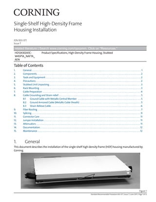
 2. Components The main components of the single-shelf HDF are shown in Figure 2. Figure 2 3. Tools and Equipment The following tools and equipment are recommended for a typical HDF installation. • 1/2-in nut driver • Phillips screwdriver • Flat-blade screwdriver • 15/16-in socket • Cable tie installation tool • Cable preparation tool kit 4. Precautions WARNING: Never look directly into the end of a fiber that may be carrying laser light. Laser light can be invisible and can damage your eyes. Viewing it directly does not cause pain. The iris of the eye will not close involuntarily as when viewing a bright light. Consequently, serious damage to the retina of the eye is possible. Should accidental eye exposure to laser light be suspected, arrange for an eye examination immediately. WARNING: DO NOT use magnifiers in the presence of laser radiation. Diffused laser light can cause eye damage if focused with optical instruments. Should accidental eye exposure to laser light be suspected, arrange for an eye examination immediately. CAUTION: Recommend the use of safety glasses (spectacles) conforming to ANSI Z87, for eye protection from accidental injury when handling chemicals, cables or fiber. Pieces of glass fiber are very sharp and have the potential to damage the eye. CABLE: CABLE: CABLE: P/N 00-534-76 ISS: 01 Strain-relief bracket Mounting bracket Slide shelf (drawer) Mounting bracket Cable entry guide Splice tray Connector support panel with connector adapters Fiber routing guides Jumper radius control guides
  • 3. Standard Recommended Procedure 003-377 | Issue 7 | June 2017 | Page 3 of 12 CAUTION: The wearing of cut-resistant safety gloves to protect your hands from accidental injury when using sharp-bladed tools and armored cable is strongly recommended. Use extreme care when working with severed armor.There will be a sharp edge where armor is cut.To minimize the chance of injury from the cut armor, cover the exposed edge with a wrap of electrical tape.To minimize the chance of injury from sharp-bladed tools, always cut away from yourself and others. Dispose of used blades and armor scrap properly. WARNING: Isopropyl alcohol is flammable with a flashpoint at 54ÂşF. It can cause irritation to eyes on contact. In case of contact, flush eyes with water for at least 15 minutes. Inhalation of vapors irritates the respiratory tract. Exposure to high concentrations has a narcotic effect, producing symptoms of dizziness, drowsiness, headache, staggering, unconsciousness, and possibly death. CAUTION: Cleaved or broken glass fibers are very sharp and can pierce the skin easily. Do not let these pieces of fiber stick to your clothing or drop in the work area where they can cause injury later. Use tweezers to pick up cleaved or broken pieces of glass fibers and place them on a loop of tape kept for that purpose alone. Good housekeeping is very important. CAUTION: Fiber optic cable is sensitive to excessive pulling, bending, and crushing forces. Consult the cable specification sheet for the cable you are installing. Do not bend the cable more sharply than the minimum recommended bend radius. Do not apply more pulling force to the cable than specified. Do not crush the cable or allow it to kink. Doing so may cause damage that can alter the transmission characteristics of the cable; the cable may have to be replaced. 5. Stubbed Unit Unpacking Follow the directions in the Corning standard recommended procedure 003-310 provided with the shipping container to remove the stubbed unit from its packaging. 6. Rack Mounting Step 1: Housings are shipped preassembled. Attach shelves to the utility rack on mounting brackets using the 12-24 x 3/8-in screws provided. Step 2: The mounting bracket may be moved forward or back 1/2 in to change the front projection of the unit (Figure 3).To change the mounting bracket location: a. Use a Phillips screwdriver to remove the two screws securing the mounting bracket. b. Relocate the mounting bracket to the desired location and reinstall the screws. c. Repeat for the other side of the unit. Figure 3
  • 4. Standard Recommended Procedure 003-377 | Issue 7 | June 2017 | Page 4 of 12 Step 3: Install housing into rack as follows: a. Slide housing into position and secure with two (2) screws on the right. b. Position the strain-relief bracket on the left side so the top of the strain-relief mounting bracket is flush with the top of the housing mounting bracket and secure with two (2) more screws (Figure 4). Figure 4 7. Cable Preparation Figure 5 Strain- relief bracket Mounting bracket (secure with two screws) Fiber # Color Length (in) 1 Blue 4.25 2 Orange 4.25 3 Green 4.5 4 Brown 5 5 Slate 5.75 6 White 6.5 7 Red 7 8 Black 7.5 9 Yellow 8 10 Violet 8.5 11 Rose 9 12 Aqua 9.5 13 Blue 6.5 14 Orange 7 15 Green 8 16 Brown 8.5 17 Slate 9 18 White 9.5 19 Red 10 20 Black 10.5 21 Yellow 11 22 Violet 12 23 Rose 13.5 24 Aqua 14 (End of sheath to tip of connector Pigtail Lengths – HDF Fiber length required for your splicing method 91 inches in top shelf (fibers 1-24) (Add 13 inches for rear cable entry.) Central member: 2 in (5 cm) Yarn: 6 in (15 cm) 900µm fiber: Fiber length required for your termination method. Subunit sheath: 1st 12 fibers: 64 in 2nd 12 fibers: 67 in See chart for pigtail length.
  • 5. Standard Recommended Procedure 003-377 | Issue 7 | June 2017 | Page 5 of 12 Step 1: Perform cable sheath removal steps per instructions for the type of cable being installed. Suggested component lengths are illustrated in Figure 5. Step 2: Terminate the cable according to the method applicable for your cable type. NOTE: Do not expose the bare fiber until you are ready to terminate it. 8. Cable Grounding and Strain-relief 8.1 Ground Cable with Metallic Central Member Ground cable with metallic central member directly to the strain-relief bracket as illustrated in Figure 6. Step 1: Place the eye of a ground wire (#6 AWG, purchased separately in appropriate length from any electrical supply store) under the washer. Step 2: Attach the other end of the ground wire to the building ground. NOTE: The ground wire must have metal-to-metal contact providing an electrical path to the central member in order to properly ground the cable. 8.2 Ground Armored Cable (Metallic Cable Sheath) Step 1: Ground armored cable using a ground clamp (Figure 7). An optional ground strap for metallic armor is available. (Order HDF-GND-1.) a. Cut a slit into opposite sides of the outer sheath and armor about 3 cm long. To do this, score the armor with a cable knife (being careful not to damage the inner sheath) and split the sheath by flexing it. b. Position the base of the grounding clamp under the armor.The stops of the clamp should just touch the outside of the armor and sheath. NOTE: The grounding clamp is generally installed below the sheath retention clamp on the strain-relief bracket. See Section 8.3 for sheath rentention clamp installation. c. Position the top plate and a lock nut on the stud. Tighten the lock nut with a 10 mm wrench so that the teach on the upper plate are driven into the sheath. d. Cover the completed assembly and the slit with a few wraps of vinyl tape. e. Place the grounding strap on top of the lock nut and secure with a second lock nut.Tighten the assembly with a 10 mm wrench. Figure 7 Frame ground wire Figure 6 1 2 3 4 3 cm (1.2 in) 3 cm (1.2 in) 6 mm (.25 in) A Stop Base Plate B E C Top Plate Grounding strap Vinyl tape D KPA-0018-3cm
  • 6. Standard Recommended Procedure 003-377 | Issue 7 | June 2017 | Page 6 of 12 8.3 Strain-Relieve Cable Step 1: Install a sheath retention clamp onto the cable sheath as illustrated in Figure 8. a. Take a section of clamp material and wrap it around the cable to determine the length needed for one full wrap. b. Use side cutters to cut the clamp material so that it ends up one section shorter than this length. c. Place the cut length of clamp material 1.25 cm (0.5 in) from the end of the cable sheath. Install a hose clamp over it, covering as many of the small holes in the clamp material as possible. Hand-tighten with a slotted screwdriver or 5/16-in nut driver. Step 2: Determine cable entry location. Cables can be strain-relieved to the side or the rear of the unit. Step 3: When your application requires side entry, attach outside plant cables to the strain-relief bracket on the left side of the utility rack using cable ties. Step 4: When central member strain-relief is required, secure the central member under the washer as shown (Figure 9). Use a central member clamp shim, if necessary, per Figure 10. a. Arrange the buffer tubes to ensure clearance around the central member and the bracket. b. Install the bolt and washers as shown and loosely install the nut. Figure 8 Figure 9 The purpose of the central member clamp shim is to ensure that small diameter central members are secured adequately when used with the central member clamp. Insert the central member into the hole in the shim. • If the central member passes through the hole, the shim is required to secure the central member. Place the shim between the U-shaped washer and the bracket. • If the central member does not fit in the hole, discard the shim. Shim Shim Central member Central member U-washer Figure 10
  • 7. Standard Recommended Procedure 003-377 | Issue 7 | June 2017 | Page 7 of 12 c. From the front side of the strain-relief bracket, wrap the strength member yarn in a clockwise direction under the head of the bolt. d. Position the central member of the cable between the washer and the bracket. e. Tighten the hex nut. f. Trim off the excess yarn and central member. NOTE: The exposed length of the central member (after strain-relief) is to be less than or equal to 6.5 cm (2 1/2 in) between the washer and the end of the cable sheath. Step 5: When your application requires rear entry of the cable, install the cable as shown in Figure 11. Figure 11 NOTE: Rear entry of the cable requires removal of the top cover of the housing. Strain-relieve the cable and secure the buffer tubes to the unit using the clips on the inside wall as shown in Figure 12. Replace the housing top cover and continue with the installation. If the cable is coming from above the unit, the strain-relief bracket can be mounted to the holes on the lip on the rear of the top cover. Figure 12 9. Fiber Routing Step 1: The connector shelf is held in place on five studs (Figure 13). Pry up the connector shelf to access the radius control guides. Top cover Cable clips
  • 8. Standard Recommended Procedure 003-377 | Issue 7 | June 2017 | Page 8 of 12 Step 2: Cable is routed into the HDF shelf through the cable entry guide and wound around radius control guides as illustrated in Figure 13. Figure 13 Step 3: Remove the appropriate size buffer tube retainer from the kit and install over the fiber as illustrated in Figure 14. Select the retainer that best fits the cable you are installing. IMPORTANT: The shelf must be pulled forward completely before routing the fibers to make sure the fibers will not be stressed when the drawer is opened. Step 4: After the fiber is routed around the guides, secure buffer tubes to the cable tie anchor using a small cable tie. Do not use a cable tie on ribbon fiber. NOTE: It may be necessary to wrap 1 in of vinyl tape around buffer tubes at the cable tie location to ensure a snug grip. DO NOT over- tighten the cable tie. Step 5: Once fibers have been routed, the connector shelf can be replaced. Figure 14 NOTE: When your application requires splicing, it will be easier to adjust fiber slack with the connector shelf removed. The fiber should be secured loosely with a cable tie until the fiber slack is routed around the guides. Then, the cable tie can be tightened. Studs Cable tie anchor
  • 9. Standard Recommended Procedure 003-377 | Issue 7 | June 2017 | Page 9 of 12 10. Splicing Pigtails are fiber optic cables with connectors at one end. The unterminated ends of pigtails are spliced to buffered or ribbon fibers in a splice tray.The splice tray is secured behind the removable connector shelf. Splice trays are ordered separately. Step 1: Refer to the instructions supplied with the splice trays and strain-relieve buffer tubes (or ribbons) and pigtails into the splice tray. Step 2: Bring both pigtails and buffered (or ribbon) fibers to a convenient splicing area - one pair at a time. Step 3: Splice the fibers as described in instructions for the splicing method you are using. Refer to Figure 5 for component lengths. Step 4: As you complete a splice, record the location on the record label on the inside cover. NOTE: Appropriate record keeping is imperative for an organized installation. Step 5: Once splicing is complete, loop slack around the radius control guides and position the fan-out body as shown in Figure 15. Step 6: Slide the completed tray under the lip at the rear of the shelf (Figure 16). Figure 15 Figure 16 Fan-out body Hook-and- loop strap Jumpers Fiber routing guides
  • 10. Standard Recommended Procedure 003-377 | Issue 7 | June 2017 | Page 10 of 12 Step 7: Pigtails are routed through the fiber routing guides behind the adapters (Figure 17). Step 8: Connector sleeve adapters are available to fit the SC, D4, ST® Compatible, and FC connector sleeves. See Figure 18 for installation of each sleeve type. Figure 18 Step 9: Adapter sleeves are installed in a connector support panel on the connector shelf. Raise the adapter to access it for connector installation (Figure 19). Step 10: Clean adapters and connectors per standard company practices or as described in Section XX. Step 11: Install connectors. NOTE: When no splicing is necessary, simply loop the fibers around the radius control guides and feed each fiber through the appropriate routing guide. Install the connectors into adapters in the connector shelf. Figure 17 D4 FC SC ST® Figure 19
  • 11. Standard Recommended Procedure 003-377 | Issue 7 | June 2017 | Page 11 of 12 11. Connector Care Step 1: Obey the following precautions in order not to damage the surface of the connector and make it unusable: WARNING: Isopropyl alcohol is flammable with a flashpoint at 54ÂşF. It can cause irritation to eyes on contact. In case of contact, flush eyes with water for at least 15 minutes. Inhalation of vapors irritates the respiratory tract. Exposure to high concentrations has a narcotic effect, producing symptoms of dizziness, drowsiness, headache, staggering, unconsciousness and possibly death. • Always keep dust caps on connectors and adapters when not in use. • Ensure dust caps are clean before reuse. • Use optical cleaning materials as standardized by your company. • Clean the connector before every mating, especially for test equipment patch cords (jumpers). • A minimum level of cleaning is listed below. Local procedures may require more rigorous cleaning methods. Step 2: Remove plugs from the connector adapter. Step 3: Wipe the connector ferrule twice with a lint-free wiping material moistened with isopropyl alcohol. Then wipe across the end of the ferrule. Step 4: Repeat previous step with a dry wipe. 12. Jumper Installation Jumpers are fiber optic cable with connectors at both ends. One end is installed in the adapter in the HDF shelf and the other end is generally connected to electronic equipment. Step 1: Route jumpers around routing guides on the shelf assembly as shown in Figure 16. Step 2: Close the shelf assembly and use the hook-and-loop strap on the side of the housing to secure the incoming bundle of jumpers. Step 3: Remove jumpers from rear jumper spool if connector shelf is to be removed. 13. Attenuators When your application requires the use of attenuators, slide the routing guides in front of the adapters out to the second position (Figure 20). Attach the attenuators between the jumper and the adapter. Attenuator position Normal position Figure 20
  • 12. Standard Recommended Procedure 003-377 | Issue 7 | June 2017 | Page 12 of 12 Corning Optical Communications LLC • PO Box 489 • Hickory, NC 28603-0489 USA 800-743-2675 • FAX: 828-325-5060 • International: +1-828-901-5000 • www.corning.com/opcomm Corning Optical Communications reserves the right to improve, enhance, and modify the features and specifications of Corning Optical Communications products without prior notification. A complete listing of the trademarks of Corning Optical Communications is available at www.corning.com/opcomm/trademarks. All other trademarks are the properties of their respective owners. Corning Optical Communications is ISO 9001 certified. © 1995, 2017 Corning Optical Communications. All rights reserved. 14. Documentation Incoming cable information may be recorded on the label on the front of the housing (Figure 21). Figure 21 15. Maintenance The unit requires very little maintenance to ensure fibers and parts remain in good condition. • External components may be cleaned occasionally with a damp, nonabrasive cloth. • Check nuts, bolts, and screws; tighten as needed. • Check fiber optic cable to make sure bends do not exceed the minimum bend radius. • Check cables for unnecessary strain, for crimping or crushing at entries and exits, and for damage. • Check unit record labels to make sure all are clear and accurate. CABLE: CABLE: CABLE: P/N 00-534-76 ISS: 01 P/N #00-536-07 1 2 3 4 5 6 7 8 9 10 11 12 13 14 15 16 17 18 19 20 21 22 23 24 Incoming cable information Record label