MSE-4105-Chapter-2-Manufacturing of Composites.pdf
6.09-kochanowski
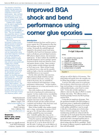
1. Improved BGA
shock and bend
performance using
corner glue epoxies
Improved BGA
shock and bend
performance using
corner glue epoxies
Improved BGA shock and bend performance using corner glue epoxies
The adoption of lead free
solders has decreased the
reliability of BGA packages
subjected to shock and
bend events. Also, as BGA
packages grow in foot print
and as pitches shrink, they
are at increased risk of failure
induced through handling.
Capillary flow underfills
can be used to significantly
enhance the reliability
performance of BGA packages.
However, underfilling larger
packages can take significant
time. This can translate to
slow assembly rates or multiple
underfill machines operating
in parallel to meet throughput
requirements.
We have explored the
technique of using corner
applied epoxies to enhance
the performance of BGA
packages. This technique is
a very effective at increasing
mechanical strength, and
can be implemented using
automated dispense machines
or by manual dispense
methods, therefore it can
be implemented on larger
packages without the beat
rate concerns associated with
capillary flow underfill.
Critical factors to the
success of this process
include selecting the proper
epoxy chemistry and using
an appropriate amount of
epoxy and the optimum
pattern for the BGA package
being protected. This paper
will quantify the mechanical
improvements seen when
applying these epoxies to
various BGA systems. The
reliability of corner bonded and
non-corner bonded devices
in response to shock and
bending will be reported as a
function of the type of epoxy
and dispense pattern used.
Equation 1.
Introduction
Underfill chemistry has been used for years to
protect against the CTE mismatch in flip chip
BGA packages and the effects of temperature
cycling. Eventually the underfill approach
migrated to the printed circuit board arena.
Underfill at the board level dominates markets
such as cell phones, personal digital assistants,
MP3 players, digital cameras, and automotive
applications. In these markets the underfills are
generally designed to protect packages against
mechanical shock, bend and vibration events
and against thermo-cycling. Many products
in these markets include packages generally
≥ 15x15 mm in size. Many of these boards
are relatively low in value and the assembly
yields are high so that the reworkability of the
underfilled devices is not required.
On the other end of the value spectrum,
high performance/high reliability markets
such as military electronics, avionics, and
medical electronics also use underfill for
various mechanical and temperature cycling
performance enhancement. In these markets,
profit margins are not as lean and rework is not a
common practice.
New niche markets are developing where
new levels of mechanical re-enforcement are
required. In these markets device reworkability
and assembly rate are of major concern. These
include medium-value, small- to medium-
footprint electronics such as high feature
cell phone boards and ultra mobile personal
computers and moderate value electronics such
as laptop, desktop, and server boards.
Many of these middle value markets require
mid- to large- sized package footprints (15x15
mm up to 50 x 50 mm) where traditional
capillary underfill becomes increasingly
slow. Underfill capillary flow time can be
approximated with the following Equation 1.(1)
Using this equation and holding all variables
constant except for the flow distance, L, and
the gap size, h, it can be shown that if a 10
mm die with a 3 mil gap size can be filled in 10
seconds then a 42 mm BGA package with a 20
mil gap size will be filled in 19.6 minutes. This
relationship will quickly drive the assembly rate
for filling large packages to unreasonable rates.
A process that makes sense for re-enforcing
these moderate valued electronics with mid- to
large-sized packages is corner glue (sometimes
called peripheral glue, corner bond or corner
tack). Corner glue includes applying an
adhesive only near the edge of a BGA or similar
package and curing. This adhesive forms a
mechanical bridge between the BGA package
and the PCB.
Corner glue has significant advantages. First,
the mechanical strength of the BGA package to
board interconnect is significantly strengthened.
The strengthening does not seem to be as much
as full capillary underfill but it may be enough
to help the at risk package pass its shock, drop,
bend, or vibration requirements. Second, the
manufacturing assembly rate achieved with the
corner glue can be much greater than that obtained
with full capillary underfill. Corner glue dispensing
can be done with a automated machine prior to
BGA placement or manually with a pneumatic
driven syringe after the BGA is assembled. Third,
the amount of adhesive required is significantly less
than with full underfill.
Keywords:
Corner glue, epoxy,
BGA, shock, bend
Michael Kochanowski
Intel Corporation
Hillsboro, Oregon, USA
michael.kochanowski@intel.com
Brian Toleno
Henkel Corporation
Irvine, California, USA
brian.toleno@us.henkel.com
This paper was originally presented
at the SMTA International
Conference, September 2006
where
T = for underfill to flow across the
package in seconds
m = underfill viscosity
L = distance for underfill to flow
h = gap between parallel surfaces
g = wetting angle of fluid to surfaces
q = surface tension of underfill.
26 Global SMT & Packaging - October 2006 www.globalsmt.net
2. Table 1. Epoxies used in this study.
Material Reference Commercial Name
Glue A Loctite 3515
Glue B Loctite 3609
Glue C Loctite 3509
Improved BGA shock and bend performance using corner glue epoxies
This can lead to material costs savings.
Fourth, since much less adhesive is used
compared to full capillary underfill, the
area of adhesive in contact with the board
and the package is smaller. This should aid
in the ability to develop systems that are
reworkable without damaging the PCB. (3)
Corner glue processes are becoming
main stream particularly with large
companies that assemble boards for laptop
computers.
Note: The words glue, epoxy and adhesive
are used interchangeably throughout this paper.
Methodology
Three epoxies were studied and are referred
to within this paper as Table 1.
Pre-reflow corner glue
assembly method
Corner glue can be applied by two
methods. The first method is pre-reflow
(also known as reflow cure). With pre-
reflow corner glue, the epoxy is applied
to the printed circuit board near the
periphery of the BGA foot print after
solder paste printing but before BGA
placement. (See Figure 1.)
With this method, an automated
adhesive dispense machine is required
to ensure that the adhesive location is
partially underneath the BGA substrate
footprint and sufficiently away from the
BGA solder lands. Dispense machines
using jet dispense technology or auger
pumps in conjunction with vision systems,
work well for this application. When pre-
reflow corner glue is used, the BGA device
is soldered in place and the glue is cured in
the same SMT oven pass.
One key attribute of an epoxy chemistry
for pre-reflow corner glue is that the epoxy
remain fluid through the early solder reflow
stages so that the BGA can self align to
the lands when the solder becomes molten.
Manufacturers of corner glue epoxies
have designed chemistries to provide this
delayed cure and self aligning feature for
both typical eutectic Sn-Pb solder (melting
point 183ºC) and for Sn-Ag-Cu (melting
point ~217ºC) lead free solder.
The amount and shape of the dispensed
glue is the cornerstone to the performance
of this process. Initial studies were done
with single dots of Glue A at each corner
of a 40x40 mm BGA package with 24 mil
solder balls. The gap between the outer
edge of the outer row of solder balls and
the outside edge of the substrate package
was 28 mils. (See Figure 14.) At the four
corners of each package we placed single
igloo shaped dots of glue with diameters at
their base of 55-70 mils and heights at the
shoulder of the kiss shape or at the top of
the igloo of >25 mils. Both time/pressure
pneumatic dispense and jet dispense
machines were used to generate these
adhesive dots.
Spherical bend and shock testing was
done on these packages and we found no
significant improvement with individual
glue dots. The failure mode in these tests
was that the solder mask on the PCB was
ripping off of the board (See Figure 2.);
thus the weakest link in this system was
the solder mask to PCB core interface.
From this result, we realized that more
total bonding surface area would make
this system more robust therefore we
decided to increase the dispensed glue from
individual glue dots at each corner to “L”
shaped lines around each corner. Earlier
finite element modeling of second level
interconnection showed us that stresses
on about the 4 most outer corner balls of
the previously tested BGA tend to get the
most concentrated stresses. Combining
these facts we decided that a starting point
of dispensed corner glue around the six
most outer solder balls (slightly more than
the 4 balls as risk) we may be able to create
a solution that adds significant protection
to this particular package. Dispensing of
glue for these builds was done using a jet
dispense machine.
A critical parameter for the control
of pre-reflow corner glue is the distance
between the dispensed glue after the
package has been placed and the nearest
pads (used to approximate the solder balls).
A square glass plate placement technique
was used to ensure that the dispensed glue
did not get too close to the outer most
BGA pads once a BGA was placed on
the board and the glue flowed under the
compression of the BGA substrate. This
set up technique included building up of
several layer of tape and then one layer
of double sided tape on the center of the
BGA package site on the board such that
the tape thickness approximates the height
of the solder balls on the BGA.
After a candidate glue pattern was
dispensed on the set up circuit board,
a glass plate with the same peripheral
dimensions of the BGA substrate was
machine placed onto the tape. Once the
glass plate was placed, we could see how far
the glue had flowed and how close to the
Figure 1. View of Corner Glue Applied to
a PCB prior to BGA placement.
Figure 1b. View of BGA placed on glue
dots prior to reflow.
Figure 2. Corner glue adheres to solder
mask as failure mode with one dot of
adhesive applied to each corner of a
package.
Figure 3. Close up of corner of
the BGA site when using the glass
plate technique for developing a
dispense pattern with some distance
measurements shown.
nearest pads it had approached through the
way that the glue wetted the plate. (See
Figure 3.)
We chose locations for measurements
of the distance from corner and peripheral
pads to the wetted glue on glass squares at
four locations. (See Figure 4.)
Through experience with pre-reflow
corner glue we developed a guideline for
27www.globalsmt.net Global SMT & Packaging - October 2006
3. the minimum distance from the outer-most
pad and the glue after compression with a
glass plate of ≥ 10 mils.
We showed that a jet dispense machine
could be set up to repeatably dispense glue
that contacts a glass plate and also does not
flow to within 10 mils of the nearby pads.
(See Figure 5.)
To enable pre-reflow corner glue work,
we recommend that the following variables
be monitored:
1. the volume and shape of the dispensed
glue,
2. the x-y position of the dispensed glue,
and
3. the x-y position of the placed package,
and
4. control of the gap between the solder
pads and the glue after placement of a
glass plate (consistently > 10 mils)
Post-reflow corner glue
assembly method
The second method for assembling BGA
components with corner glue is applying
the epoxy to the package post-reflow.
In our studies, a manual glue dispense
process was used to inject glue at the
component corners. We expect that an
automated glue dispense process could also
be developed that would give similar results
to those we are describing in this paper.
Through experience and modeling we
know that the corner solder joints of BGA
packages tend to be at the highest risk to
failure in shock and bend events because of
the stress concentration at these locations.
Glue was injected around the four corners
of each BGA part in an ‘L’ shaped pattern.
During the application, the objective
was to dispense a bead of material that
made full contact with the board and also
Figure 4. Approximate locations (A,
B, C, and D) used to measure the
glue flow out distance, the distance
between the wetted glass plate and
the nearest BGA pad.
Figure 5. Glue edge to pad distance monitored through a glass plate taken a two
opposing corners of a BGA footprint through 26 dispense cycles versus a target
minimum gap of 10 mils.
Figure 7. Depiction of two ball deep
corner glue.
contacted the edge of the package at least
half way up the side of the package. (See
Figures 6.)
The length of the dispense for each
side of the ‘L’ shaped line was chosen to
totally cover the entire depth of either 2,
4 or 6 BGA solder balls on each side of
the package throughout the experimental
legs included in this paper. This length
of dispense was based on some inferences
that we made from other related
mechanical modeling and observations of
systems without glue. Based on this and
other work we believe that corner glue
application in the range of 2-6 balls deep
along the side of a BGA package is a good
starting point for evaluation of packages
with pitches in the range of 0.8 - 1.27
mm. We define two ball deep corner glue
as having the length of the line of glue
extend from the corner of the package at
least to the furthest edge of the second ball
counting from the corner of the package on
each side. (See Figure 7.)
During the dispense process some of the
epoxy flows underneath the bottom of the
attached BGA part. Inevitably some of the
epoxy may flow far enough that it contacts
the outermost solder balls. We have seen
this phenomenon and as far as from our
observations it has not detrimentally
impacted mechanical performance.
For this work, an EFD Model XL1500
pneumatic dispense machine was used
with air pressure settings of 15-18 psi and
all-plastic 18 gage dispense tips. Our
guideline for selecting the tip diameter is
to have the top of the dispense tip reach
at least 50% of the way up the side of
the BGA package when the tip is placed
against board at the base of the assembled
package. (See Figure 8.)
Figure 6. Cross-section of corner glue
after cure.
Glue was dispensed with the tip at
approximately a 45∞ angle away from
the package on the printed circuit board
at approximately a 45∞ angle toward the
direction of travel of the tip across the
board. (See Figures 9 and 10, respectively.)
Two packages were used for our
experiments with post reflow corner glue.
Improved BGA shock and bend performance using corner glue epoxies
28 Global SMT & Packaging - October 2006 www.globalsmt.net
4.
5. Improved BGA shock and bend performance using corner glue epoxies
30 Global SMT & Packaging - October 2006 www.globalsmt.net
Figure 8. Diagram of well chosen
syringe for corner glue application.
Figure 9. Corner glue dispense angle
- horizontal view.
Figure 10. Corner glue dispense angle
- overhead view.
Figure 11. Wave front of corner glue
flowing from under BGA package during
corner glue application.
The first package was a 35 x 35 mm 1.27
mm pitched package with a distance of
46.5 mils from the edge of the outer solder
balls to the package edge. The second
package was a 40 x 40 mm 1.0 mm pitched
package with a distance of 28 mils from
the edge of the outer solder balls to the
package edge.
Dispensing of corner glue is technique
dependent. The objective with the corner
glue application is to have a large surface
area of glue in contact with both the
vertical outer edge of the BGA package
and the bottom of the BGA package. To
maximize the amount of glue going under
the package, the rate at which the syringe
tip was moved across the package was kept
slow enough that a wave front of glue that
could be seen slightly leading the syringe
tip. This wave front was a visual indication
that at least some glue was being forced
underneath the package. (See Figure 11.)
The following minimum cure schedules
were used for the glues in this study as per
the vendor’s recommendations.
The amount of Glue C and Glue A
dispensed in these studies average 0.096
and 0.090 grams per package, respectively,
for a 2 ball deep application with a 40 x
40 mm, 1.0 mm pitched BGA package
with 24 mil solder balls. The amount of
glue dispensed was determined visually
through the efforts of the operator to
ensure coverage of the number of solder
balls targeted by the particular process. For
our process control the mass of glue used
was not considered as important as having
the glue contact the board and the package
throughout the prescribed lengths. The
amount of Glue B used is not reported as
this material did not perform well in this
testing.
We recorded the time required to
dispense corner glue at 6 balls deep around
the 37.5 x 37.5 mm packages with a ball
pitch of 0.8 mm. Again, the equipment
used was the EFD 1500XL machine with
Glue C with a 22 gage plastic tip. The
time required per package averaged was 67
seconds. This manual dispense process was
not optimized to increase the flow speed
using dispense tip gage and air pressure and
therefore we expect that there is room for
improvement if required for high volume
manufacturing.
Results
Pre-reflow corner glue has limitations. A
key parameter for this approach is the
distance on the target BGA package
between the outer BGA ball and the outer
Table 2. Cure times and temperatures of epoxies used in this study.
GlueType CureTime CureTemperature
Glue A 30 minutes 150 ºC
Glue B 10 minutes 100 ∞C
Glue C 40 minutes 150 ∞C
edge of the package. This distance is used
to create a bond line between the epoxy
and the package. (See Figure 12.)
From some builds that we conducted we
estimate that the minimum dimension for
the package edge to solder ball for using
pre-reflow corner glue with a jet dispense
machine is 28 mils. If the corner glue
dispense machine uses a larger dispense
needle such as in an auger pump or a
piston/syringe pump this critical dimension
is probably significantly larger. (Dispense
accuracy is related to the variation in how
the fluid breaks off from the dispensing
needle. Jet dispense systems are the most
accurate technology being used today
and auger, pneumatic, and piston pump
systems tend to be less accurate.(4))
This
dimension is important because the process
must be designed so that the uncured
glue does not flow into the region of the
solder ball and pad wetted with paste and
compromise the quality of the final solder
joint. (See Figure 13.)
All of our pre-reflow studies were done
with corner glue with a 40 x 40 mm, 1 mm
pitched BGA package with 24 mil solder
balls. The material that performed well in
our testing was Glue C. We also performed
some shock testing with Glue A and Glue
B in some earlier screening work and we
got a lower degree of improvement with
Glue A and no improvement with Glue B.
The Glue A and B results are not included
in this paper.
A transient bend test was used to
evaluate the mechanical improvement of
the second level interconnection made
when using corner glue. The bend set up is
shown in Figure 14.
Bend tests were run with a displacement
rate of 5 mm/sec, a span distance on the
supports of 120 mm (3x the package width)
and with all bends done until electrical
opens occurred on with daisy chained
packages. Strain gages were attached at
control locations on the BGA package
surface and on the printed circuit board as
shown in Figure 15.
We used transient bend testing on a
0.093 inch thick printed circuit board to
evaluate the performance of the pre-reflow
applied corner glue. This experiment had
three legs: (1)
glue was applied four balls
deep down the side of the package; (2) six
balls deep down the side of the package,
7. Improved BGA shock and bend performance using corner glue epoxies
32 Global SMT & Packaging - October 2006 www.globalsmt.net
Figure 12. Key dimension to determine
if pre-reflow corner glue can be applied
for a BGA package.
Figure 13. Area at risk for glue
contaminated solder joint if the glue
flows too far after BGA placement.
Figure 14. Drawing of bend test set up.
Figure 15. Strain gage locations.
and (3)
no glue. For each leg four boards
were tested in transient bend. We
measured the strain level of the boards
where we began to see the initial onset
of mechanical damage and compared
these levels to the same type of data on
boards without any glue. As expected the
four and six ball deep glue improved the
performance of the packages significantly.
The four ball deep increased the strain
level where mechanical damage occurred
by 18% and six ball deep glue improved
it by 25%. (See Figure 16) The six ball
deep glue also required 40% more force to
initiate mechanical damage.
Post-reflow corner glue
All of our studies were done with corner
glue with a 40x40 mm, 1 mm pitched BGA
package with 24 mil solder balls.
We had the following results:
1. Glue B, 6 balls deep showed no
improvement during bend testing.
This was expected because Glue B was
designed as a passive chip bonding epoxy
use to secure parts prior to wave solder.
It was know that this glue had less
strength than the others tested.
2. Glue A, 2 balls deep showed no
improvement in shock or bend testing.
3. Glue A, 6 balls deep showed marginal
improvement in bend and no
improvement in shock.
4. Glue C showed the most significant
improvement in bend.
Glue C results are summarized below.
In shock testing, Glue C applied two
balls deep allowed the package tested to
withstand 50% higher G forces before
electrical opens occurred in the package
when compared to the same packages with
no glue. (300 G versus 200 G)
We conducted transient bend testing
on a 0.062 inch thick printed circuit board
to evaluate the performance of the pre-
reflow applied corner glue. This designed
experiment glue had two legs; glue applied
to boards six balls deep down the side of
the packages and no corner glue. For each
condition seven boards were tested in
bend. We measured the strain level of the
boards where we began to see the initial
onset of mechanical damage and compared
these levels to the same type of data on
boards without any glue. The six ball
Figure 16. Improvement in Strain Level where the onset of mechanical damage
occurred in boards for boards with glue 4 balls deep, 6 balls deep versus the
performance of packages without any corner glue in transient bend testing.
deep glue improved the strain level of the
packages where the onset of mechanical
damage occurred by 107% which also
required 140% more force to initiate
damage. (See Figure 17.)
Failure modes of corner glued
samples in bend testing
The predominant failure mode for boards
sent through bend testing without corner
glue was pad cratering on the board side of
the BGA ball (See Figure 18).
All corner glued packages that we tested
in bend testing (both the 4 ball and 6 ball
deep) had a predominant failure mode in
bend where a crack began in the vicinity
of the glue to package substrate interface
and propagated along the package to ball
interface. (See Figure 19.)
Failure modes of corner glued
samples in shock testing
The predominant failure mode for boards
sent through shock testing without corner
glue was pad cratering on the board side of
the glue deposit and BGA ball (See Figure
20 and 21).
Rework
We attempted to rework some 31x31 mm
BGA packages assembled to boards using
Glue C, 6-balls deep in each corner applied
post-reflow. We used an SRT Model 1100
and a rework temperature profile previously
developed for this package without any
corner glue. (See Figure 22.)
Unfortunately, we were not successful in
removing BGAs attached using corner glue.
8. You should.
Juki is one of the world's leading placement companies
with over 15,000 machines installed worldwide. More
than half of those are in China, and they are doing quite
well with them.
Tokyo Shanghai Shenzhen Beijing Singapore Raleigh San Jose Sao Paolo Buenos Aires Nuremberg London Switzerland
www.jas-smt.com
Know JUKI?
The Lowest Cost of Ownership - Period
9. Improved BGA shock and bend performance using corner glue epoxies
34 Global SMT & Packaging - October 2006 www.globalsmt.net
Figure 17. Improvement in Strain Level
where the onset of mechanical damage
occurred for boards with and without
corner glue in transient bend testing.
Figure 18. Predominant failure mode
for BGA packages in bend without
corner glue.
Figure 19. Predominant failure mode
for BGA packages in bend with corner
glue present.
Figure 20. Photograph of common
failure mode for BGA packages in
shock with corner glue; crack at board
surface very near glue that propagates
as a crater beneath the glue.
Figure 21. Predominant failure mode
for BGA packages in shocked with
corner glue present.
The two events that occurred were first,
the part lifted off of the board but most of
the glue remained in tact with the BGA.
And second, when the glue lifted it ripped
substantial sections of solder mask off of
the board thus jeopardizing the integrity of
the board. (See Figure 24.) In other cases,
we found that when lifting the BGA part,
the solder mask on the BGA itself tended
to crack and splinter, leaving a glob of
adhesive on the printed circuit board.
(See Figure 25.)
Experts in the art of reworking packages
secured with corner glue epoxies have
noted that this process can be done. One
key to rework is using a twisting force
which was not present in our experiments.
The authors of this paper can refer those
interested to experts in rework if required.
Modeling bend using finite
element analysis
Finite element analysis modeling was
done to understand the performance of
this system in spherical bend at low strain
rates.(2)
A quarter symmetry model of a
typical CPU BGA attached to a printed
circuit board with characteristics of
motherboards in common laptop computers
both with and without corner glue was
used. The modeled CPU package was
a 1.27 mm pitch, 35 x 35 mm footprint
with 28 mils of gap between the edge of
the outermost solder balls and the edge of
the package. From this modeling we have
made the following observations:
1. Corner glue helps match the BGA
package substrate curvature and the
Figure 22. Rework temperature profile.
Figure 23. Corner glue “locks” board
to BGA substrate so that these planes
bend in unison.
Figure 24. Rework site on board where
solder mask has been ripped up.
Figure 25. BGA package damage
during rework where polymer and
solder mask fragment remain behind
on board.
10.
11. Improved BGA shock and bend performance using corner glue epoxies
36 Global SMT & Packaging - October 2006 www.globalsmt.net
board curvature during bend which
translates into less stress/strain on the
solder joints. (See Figure 24.)
2. Corner glue puts a lot more stress on
the printed circuit board in the vicinity
of the cured glue at the farthest distance
from neutral point of the BGA package.
(See Figure 25.)
3. Corner glue puts higher stresses on the
die edge of the BGA package.
However, we do not understand the
quantity of stress that is required to
significantly increase the risk of
disturbing the die and we have no
information thus far saying that corner
glue has negatively affected any
package die.
4. Strains calculated using the finite
element analysis correlate well with
strain gage readings taken from actual
boards with properties from which the
model was constructed.
Summary
1. Corner glue requires significant surface
area contact to work well in medium to
large packages. (2 to 6 ball deep with at
least 50 % fillet heights gained
significant improvement in typical
shock and bend studies with the
packages we tested.)
2. Pre-reflow corner glue cannot be
done in high volume without automated
dispense equipment. We expect that the
smallest packages that can be assembled
with pre-reflow corner glue at ≥ 1.0
mm pitch with substrate edge to BGA
ball diameters of ≥ 28 mils.
3. Post-reflow corner glue can be
Figure 26. Stress maps of BGA
package during bend without and with
corner glue. Note highest stress area
as denoted by warmer colors (red/
orange/yellow).
implemented with any package size.
4. Corner glue significantly improves
shock and bend performance. Examples
include a 50% increase in G level
(200 to 300 G) in shock levels where
mechanical damage occurs and a 40%
increase in force required in bend where
mechanical damage occurs.
5. Critical parameters to implementing
corner glue include:
a. Selecting an appropriate chemistry.
b. Using enough epoxy so that the
surface area in contact with the board
and the package is significant.
c. Ensuring that the package and board
are wetted with glue before cure.
Conclusions
Corner glue adds significant mechanical
strength to packages. Although, as a class,
it is not as strong as traditional capillary
underfills, it may be strong enough to help
products in many market segments meet
their performance requirements.
Corner glue may offer advantages
to traditional capillary flow underfill
especially in medium to larger packages.
These include lower material usage,
the ability to be manually dispensed
and potential reworkability advantages.
Overall this approach may be much less
costly than full capillary flow underfill
based on epoxy cost, capital for dispense
cost and savings associated with the
potential to rework BGA packages.
Acknowledgements
We would like to express our appreciation
to Todd Embree for helping with photos,
Karumbu Meyyappan for the finite
element modeling work, Alan Mcallister
for supporting the shock and transient
bend testing, Alan Donaldson provided
evaluation on reworkability, and Frank
Toth for providing cross section data. (All
Intel employees).
Pre-reflow corner glue studies were
executed with the help of Tom White,
Dan Maslyk of Henkel; Ruben Torres-
Rodriguez, Don Woomer, and Tory Darling
of Intel; and Floriana Suriawidjaja of
Asymtek.
References
[1] Alec J. Babiarz, Horatio Quinones,
and Robert Ciardella, ‘Fast
Underfill Process for Large to Small
Flip Chips’, Proceedings of the Pan
Pacific, Kauai, HI, February 2001.
[2] Karumbu Meyyappan, Alan
McAllister, Mike Kochanowski,
and Ife Hsu, ‘Effects of Glue on the
Bend Performance of Flip Chip
Packages’, IEEE CPMT Paper,
submitted for publication.
[3] Brian J. Toleno and Josef
Schneider, “Processing and
Reliability of Corner Bonded CSPs’,
Proceedings from International
Electronics Manufacturing
Technologies Symposium, February
2003, IEMT paper
[4] Alec Babiarz, ‘Advances in Jetting
Small Dots of High Viscosity
Fluid for Electronic and
Semiconductor Packaging’, Pan
Pacific, 2006