
Recommended
More Related Content
Similar to PS_CPU_DI_DQ.ppt
Similar to PS_CPU_DI_DQ.ppt (20)
Recently uploaded
Recently uploaded (20)
PS_CPU_DI_DQ.ppt
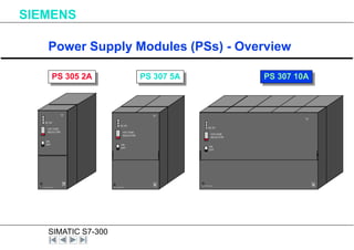
- 1. SIMATIC S7-300 Power Supply Modules (PSs) - Overview PS 305 2A 365 - 0BA01- 0AA0 X 2 3 4 PS307 5A DC 5V VOLTAGE SELECTOR ON OFF PS 307 5A 307 - 1BA00- 0AA0 PS307 5A X 2 3 4 DC 5V VOLTAGE SELECTOR ON OFF 307 - 1BA00- 0AA0 PS307 5A X 2 3 4 DC 5V VOLTAGE SELECTOR ON OFF PS 307 10A SIEMENS
- 2. SIMATIC S7-300 Power Supply Module - Front Plate Control SIEMENS 230V Voltage Selector Switch LED for 24V DC L1 N L+ M L+ L+ M M E Terminals for 24V DC output Voltage
- 3. SIMATIC S7-300 Power Supply Modules - Features Characteristics High efficiency Fan-free operation Making current limited in accordance with NAMUR recommendation Short-circuit-proof outputs Electromagnetic emission and immunity corresponding to EN50081-2/EN50082-2 SIEMENS
- 4. SIMATIC S7-300 Power Supply Modules - Electrical Specifications Details PS 307 2A PS 307 5A PS 307 10A Input Voltage 120/230V AC 120/230V AC 120/230V AC Max. Output Current 2A 5A 10A Short cct. Protection Yes Yes Yes Output Voltage 24 DC±5% 24 DC±5% 24 DC±5% SIEMENS
- 5. SIMATIC S7-300 SIMATIC S7- 300 System. SIEMENS
- 6. SIMATIC S7-300 CPU314 SIEMENS SF BATF DC5V FRCE RUN STOP RUN-P RUN STOP M RES SIMATIC S7-300 Battery MPI CPU315-2 DP SIEMENS RUN-P RUN STOP M RES SIMATIC S7-300 Battery DP SF BATF DC5V FRCE RUN STOP MPI SF DP BUSF CPU 31X CPU 31X-2DP SIMATIC S7- 300 : CPU Front Plate Controls. SIEMENS
- 7. SIMATIC S7-300 Central Processing Unit ( CPU ): LED Indicators SIEMENS CPU 312 IFM CPU 313 CPU 314/ 314 IFM CPU 315/ 315-2DP CPU 316-2DP CPU 318-2 SF BATF DC5V FRCE RUN STOP SF BATF DC5V FRCE RUN STOP SF DP BUSF CPU in RUN CPU in STOP Physical bus fault 5V DC Supply Battery fault Group fault Forcing No configuration or incorrect configuration
- 8. SIMATIC S7-300 Central Processing Unit ( CPU ): Mode Selector Switch SIEMENS RUN _ P RUN STOP RUN_P : • The CPU scan the User Program. • The key cannot be taken out in this position. • Reading a program from CPU is possible • Changed program can loaded into the CPU RUN : • The CPU scan the User Program. • The key can be taken out in this position. • Reading a program from CPU is possible • Changed program can not be loaded into the CPU STOP : • The CPU does not scan the User Program. • The key can be taken out in this position. • Reading a program from CPU is possible • Changed program can be loaded into the CPU MRES MRES : • The momentory contact position for resetting the CPU memory. • You must observe the special procedure for it. • The contents of integrated retentive memory remains unchanged.
- 9. SIMATIC S7-300 Central Processing Unit ( CPUs ): SIEMENS Types of CPUs Modular ( without I/Os) CPU with MPI Port CPU with MPI Port + DP Port MPI Port Local I/Os CPU 312 IFM CPU 314 IFM CPU 313 CPU 314 CPU 315 MPI Port CPU 315-2DP CPU 316-2DP CPU 318-2DP DP-Port Stand alone ( with local I/Os)
- 10. SIMATIC S7-300 CPU 318-2 84 K / 256 Kbyte 512 Kbyte yes 1024 256 0,1 ms 8192 512 512 PROFIBUS-DP (Master/Slave) with 125 stations; MPI usable as DP (12 MBaud) Instructions/Data User memory Free addressing DI / DO AI / AO Processing time/ 1 K bin. instructions Bit memories Counters Timers CPU 314 8 K / - 24 KByte no 1024 256 0,3 ms 2048 64 128 CPU 313 4 K / - 12 Kbyte no 256 64 0,6 ms 2048 64 128 CPU 315 (CPU 315-DP) 16 (21) K / - 48 (64) KByte no (yes) 1024 256 0,3 ms 2048 64 128 (PROFIBUS- DP interface master/slave with 64 DP- stations) CPU 316-2DP 42 K / - 128 KByte yes 1024 256 0,3 ms 2048 64 128 PROFIBUS- DP interface master/slave with 64 DP- stations Central Processing Unit ( CPUs ): Specifications SIEMENS
- 11. SIMATIC S7-300 CPU 312 IFM 2 K 6 KByte no 256 64 0,6 ms 1024 32 64 10 DI / 6 DQ Instructions User memory Free addressing DI / DO AI / AO Processing time/ 1 K binary instructions Bit memories Counters Timers For integrated functions CPU 314 IFM 10 K 32 KByte no 1024 256 0,3 ms 2048 64 128 20 DI / 16 DQ / 4 AI / 1 AQ IFM Central Processing Unit ( CPUs ): Specifications SIEMENS
- 12. SIMATIC S7-300 SMs (Digital) - Basic Characterisitcs SIEMENS 331 - 7KF00 - 0AB0 SM 331 AI 8x12 Bit S F X 2 3 4 Digital signals from 24 to 230 V, DC or AC, 20- or 40-pin front connector with screw- type connections and spring-loaded connections Powerful modules Process interrupt Diagnostics interrupt Setup via parameterization, no more hardware settings
- 13. SIMATIC S7-300 Digital Input Module: SM 321( 24V DC ) L+ 24V Mint S7-300 Backplane Bus. M Sensor 331 - 7KF00 - 0AB0 SM 331 AI 8x12 Bit S F X 2 3 4 SM 321 ( DI ): Simple Block Diagram SIEMENS
- 14. SIMATIC S7-300 Digital Input Module: SM 321 3 3 1 - 7 K F 0 0 - 0 A B 0 S M 3 3 1 A I 8 x 1 2 B it S F X 2 3 4 SM 321 ( DI ): Module Overview SIEMENS Module Description Number of Channels Rated input Voltage Diagnostic& Hard ware Interrupt SM 321: 6ES7 321 1BLx0 0AA0 32 X 24 V DC No SM 321: 6ES7 321 1BH02 0AA0 16 X 24 V DC No SM 321: 6ES7 321 7BHx0 0AA0 16 X 24 V DC Yes SM 321: 6ES7 321 1BH50 0AA0 ( Source type ) 16 X 24 V DC No SM 321: 6ES7 321 1CH80 0AA0 16 X 48 - 125 V DC No SM 321: 6ES7 321 1EH01 0AA0 16 X 120 VAC No SM 321: 6ES7 321 1EL00 0AA0 32 X 120 VAC No SM 321: 6ES7 321 1FFx1 0AA0 8 X 120/230 VAC No X = 0,1,2 etc.
- 15. SIMATIC S7-300 SM 321 ( DI ): Specifications SIEMENS Digital signals from 24 to 230 V, DC and AC. 20- or 40-pin front connector with screw-type connections and spring-loaded connections Powerful modules Process interrupt Diagnostics interrupt Setup via parameterization, no more hardware settings Status : Yes, Green LED per channel. No. of Channels : 8, 16, 32. All Modules are Single Width ( 125 X 130 X40 mm )
- 16. SIMATIC S7-300 Digital Output Module: SM 322( 24V DC) 331 - 7KF00 - 0AB0 SM 331 AI 8x12 Bit S F X 2 3 4 SM 322 ( DQ ): Simple Block Diagram SIEMENS 24V M Min t S7-300 Backplane Bus. L +
- 17. SIMATIC S7-300 Digital Output Module: SM 322 3 3 1 - 7 K F 0 0 - 0 A B 0 S M 3 3 1 A I 8 x 1 2 B i t S F X 2 3 4 SM 322 ( DQ ): Module Overview SIEMENS Module Description Number of Channels Rated output Voltage/current Diagnostic&Hard ware Interrupt SM 322: 6ES7 322 1BL00 0AA0 32 X 24 V DC/0.5A No SM 322: 6ES7 322 1BHx1 0AA0 16 X 24 V DC/0.5A No SM 322: 6ES7 322 1BF01 0AA0 8 X 24 V DC/2A No SM 322: 6ES7 322 8BFx1 0AA0 8 X 24 V DC/0.5A Yes SM 322: 6ES7 322 1CF80 0AA0 8 X 48 - 125 V DC/ 1.5A No SM 322: 6ES7 322 1EH01 0AA0 16 X 120 VAC/1A No SM 322: 6ES7 322 1FFx1 0AA0 8 X 120 /230VAC/2A No SM 322: 6ES7 322 1EL00 0AA0 32 X 120 VAC / 1A No X = 0,1,2 etc.
- 18. SIMATIC S7-300 SIEMENS M Mint S7-300 Backplane Bus. L + 24V Block Diagram : SM 322 ( Digital Relay Output ) : Simple Block Diagram
- 19. SIMATIC S7-300 SM 322 ( DQ , Relay ) : Module Overview SIEMENS 3 3 1 - 7 K F 0 0 - 0 A B 0 S M 3 3 1 A I 8 x 1 2 B i t S F X 2 3 4 Module Description Number of Channels Rated output Voltage / Current Number of outputs SM 322: 6ES7 322 1HH00 0AA0 16 X 24 - 120 V DC/2A - 0.2A 48 - 120 VAC/1.5A-0.5A Isolated in group 8 SM 322: 6ES7 322 1HF01 0AA0 8 X 24 - 120 VDC/ 2A - 0.2A 48 - 230 VAC/2A - 0.5A Isolated in group 2 SM 322: 6ES7 322 1HF80 0AA0 8 X 24 to 120 VDC 48 to 230 VAC Isolated in gp. 1 5A REL. SM 322: 6ES7 322 1HF20 0AA0 8 X 24 to 120 VDC 48 to 230 VAC Isolated in gp. 1 5A REL.
- 20. SIMATIC S7-300 SM 322 ( DQ ) : Specifications SIEMENS Different voltages 24 - 120 V DC; 120 - 230V AC Different number of channels 4, 8, 16 or 32 channels Different output currents 0.5; 1 ; 1,5 ; 2 ; 3 or 5 A Electronic / relay outputs Modules with/without diagnostics capability (Front connector unplugged; module defective indication; short-circuit; etc.) Status : YES, Green colour LED per channel
Editor's Notes
- 2
- 3
- 4
- 7
- 7