1. Abstract
RELIABILITY ASSESSMENT OF A BUS TRANSIT NETWORK
Author: Marc Mart´ınez G´omez
Advisors: Maribel Ortego Mart´ınez, Juan Jos´e Egozcue Rub´ı
key words: Bus bunching, Reliability, Risk, Vulnerability, Adaptive strategy, Monte Carlo
simulation, Operations, Public transportation.
Experience shows that buses covering busy lines with short headways tend to arrive irregularly
at their stops, often in bunches and therefore remarkably affecting the service. Although transit
agencies insert slack into their schedules to alleviate this problem, their attempts often fail
because of the remarkable fluctuations in passenger arrivals and external disruptions. Hence,
the present work aims to conduct a reliability assessment of a bus transit line, drilling down
into the underlying causes that end up affecting the service and analyzing an adaptive control
scheme to attenuate the problem.
In order to idealize the challenging conditions where a line operates, an stochastic model is
presented. The variability and randomness introduced into the system are achieved through
the generation and allocation of passengers and travel time as random variables. The main
strength of this scheme is that, apart from meeting its purpose of inserting uncertainty, is
based on experimental data collected in the line, offering therefore enough flexibility to be
extrapolated to each particular scenario.
In this manner, the validation of the model is tested in an ideal line whose physical layout
and assumptions are based on a real line from Barcelona’s network. Two main goals are
pursued. Firstly, identifying the potential improvements in service and reliability of an adaptive
strategy where buses adapt their positions depending on the magnitude of the disruptions.
Secondly, to quantify vulnerability and variability in that service. At this point is where the
Monte Carlo simulations are considered, highlighting how this method is capable to address
risk quantification with a reasonable cost.
Hence, as a supporting tool to the decision making process, the findings from this thesis have
enabled to reach meaningful conclusions from two different perspectives. On the one hand, they
provide insights into what strategies transportation agencies should deploy in order to tackle
the reliability problem. On the contrary, they describe an analytical procedure that allows
operators to quantify the risk faced when it comes to deciding what strategy should be pursued
in the long term.
4. Chapter 1
Introduction
The attractiveness of public transportation modes such as bus transit networks is a crucial issue
to ensure its competitiveness against private modes, specially nowadays that society is bound
to move towards sustainable transportation models. When deciding to make a trip, passengers
have a wide variety of modes available and their final chose will mainly depend on the quality
of service perceived. If a line has a reputation of being unreliable, that is a clear disincentive for
the society to use it. Public transportation is the single mode in which operational maintenance
costs are shared by all users. Transportation agencies are facing significant challenges trying to
produce reasonable services to a diverse set of users and trips without cost being too high. As a
result of that, public transportation modes have a tendency to present deficit problems, having
hence to be subsidized by the government. However, a trade-off must be made between the
quality of service that passengers desire and the quality that the operator can afford to provide.
Better quality of service increase potential generating higher ridership but also generates higher
costs.
Once a transit network has been defined physically for a given demand, quality of service
depends to a great extent on the management strategies and operational decisions made by
the transit agency, always subjected to its budget constraints. Variables such as frequency,
headway or waiting passenger time affects dramatically the performance of the system from
the passengers point of view and, at the same time, are the cost key drivers from the operator
perspective. Under this scenario where different needs are present and the resources are scarce,
operational and management strategies play a massive role.
Apart from that and focusing on the goal of this thesis, let’s consider the different aspects
that could induce problems in a bus during its route trip. Buses drive along infrastructures
which are shared by cars and pedestrians, exposed therefore to different exogenous factors
that significantly influence their velocity and delay from station to station. Moreover, in busy
lines with short headways passenger arrivals at station are likely to be random, uneven and
with an important variability that results in uneven passenger loading. Just considering the
former aspect and ignoring the random arrival, a delayed bus will have to pick up not only
its passengers but also those arrived early for the following vehicle. This time dwelling will
propagates in the next station and the bus will tend to fall farther and farther behind schedule.
Marc Mart´ınez G´omez Page 3 of 81
5. CHAPTER 1. INTRODUCTION
If a large passenger arrival is incorporated into this scenario, the result is the bus bunching
problem, the tendency of the buses to bunch during service, arriving irregularly at stations and
affecting dramatically the service. It is well known from experience and theory that bus motion
in this kind of system is unstable by nature and even if busses starts with perfect headway they
eventually become irregular and bunch up.
1.1 The bus bunching problem
The bus bunching problem is intrinsically related to the high susceptibility of bus transit lines
to external disturbances. The root cause of the problem is that the time a bus spends at a stop
increase with the number of passengers that board and alight the vehicle, and this time tend
to vary remarkably because of both random effects of traffic conditions and passenger arrivals.
If a bus is slowed down because of a small disruption so that the number of passengers arriving
at the stop is larger than expected, that bus will have to dwell longer. The same can be said in
case a bus arrives sooner at a stop, it will have fewer passenger to serve, speeding up further.
The problem is exacerbated over time until the busses end up having no space, moving as a
single unit and serving the same demand. Additionally, conventional buses are composed of
only one point to entry and some users interact with the driver to pay the fare. This idea makes
the dwelling time to fluctuate very significantly from bus to bus, introducing randomness in
the system and causing unreliability. According to the Transit Capacity and Quality of Service
Manual(see TRB (4)), bus bunching is caused by a number of factors, some under the control
of transit operator and some not. These factors include:
• Traffic conditions (for on-street, mixed-traffic operations), including traffic congestion,
traffic signal delays, parking maneuvers, incidents, etc;
• Road construction and track maintenance, which create delays and may force a detour
from the normal route;
• Vehicle and maintenance quality, which influence the likelihood that a vehicle will break
down while in service;
• Vehicle and staff availability, reflecting whether there are sufficient vehicles available to
operate the scheduled trips (some vehicles will be undergoing maintenance and others
may be out of service for various reasons) and whether sufficient operators are available
on a given day to operate those vehicles;
• Transit preferential treatments, such as exclusive bus lanes or conditional traffic signal
priority that operates only when a bus is behind schedule, that at least partially offset
traffic effects on transit operations;
• Schedule achievability, reflecting whether the route can be operated under usual traffic
conditions and passenger loads, with sufficient layover time provided for operators and
sufficient recovery time to allow most trips to depart on time even when the previous trip
arrived late at the end of the route;
Marc Mart´ınez G´omez Page 4 of 81
6. CHAPTER 1. INTRODUCTION
• Line merges, on rail systems, where one train arrives at a merge point behind schedule
and creates a cascading series of delays to subsequent trains;
• Evenness of passenger demand, both between successive vehicles and from day to day for
a given vehicle and run;
• Differences in operator driving skills, route familiarity, and adherence to the schedule-
particularly in terms of early (”hot”) running;
• Wheelchair lift and ramp usage, including the frequency of deployment and the amount
of time required to secure wheelchairs;
• Environmental conditions, such as snow, ice, extreme heat or cold, or leaf fall;
• Route length and the number of stops, which increase a vehicle’s exposure to events that
may delay it-delays occurring earlier along a route result in longer overall trip times than
similar delays occurring later along a route; and
• Operations control strategies used to react to reliability problems as they develop, thus
minimizing the impact of the problems.
1.2 Consequences of bus bunching
1.2.1 Effect on transit users
The main consequences of the bus bunching problem are the disruptions which cause in the
system, affecting the quality of service perceived by the users. Firstly, bunching effects will
induce that many locations along the route won’t be served by buses for long periods of time.
There is inherent unreliability on the system and users are cannot reasonably estimate the time
required to leave home and arrive to their destination, having hence to budget extra time and
creating a substantial disincentive to use bus.
In addition to longer waiting time and the need to buffer extra time, bus bunching also induces
speed and capacity problems. Due to the fact that demand served by a bus depends on the
time between bus arrivals at each stop, there will be more passengers served late than early.
The user not only waits longer for a bus, but also gets frustrated having to travel on a crowded
bus. These crowded buses will be dwelling significantly at stops because of the large number
of boarding and alighting passengers and will eventually cause slower travel times.
1.2.2 Effects on the transport agency and society
In order to maintain public transportation as an attractive mode of transport the service
provided must be fast, convenient and reliable. If a bus line starts to be perceived as unreliable
Marc Mart´ınez G´omez Page 5 of 81
7. CHAPTER 1. INTRODUCTION
the demand will plunge, having to reduce services, increase fares or investing more resources to
mitigate the lack of efficiency in the operation process. Moreover, the political pressure toward
more environmentally mode of transport puts both society and the government into a very
complex situation, having to decide whether to divest or invest resources to provide an unused
and poor performance service.
Moreover, the problem could lead to hostility work environment within the drivers collective,
who are directly exposed to unsatisfied passengers. If more resources are not allocated, the
unreliable trips and deviations from schedule will also affect the lay-over time that a driver has
defined by legal unions at terminals or headers.
1.3 Objectives
The main objective of this Master’s Thesis is to explore further the bus bunching phenomena
in a bus line, presenting different strategies to address the problem and mitigate the effects.
A stochastic model will be presented to demonstrate the feasibility of the control and its
application in real lines. The model is capable of representing the operational activity of a bus
transit line and the different disruptions that eventually end up causing bunching effects and
deviations from schedule. At the same time and with the purpose to demonstrate its feasibility,
the model is tested on an ideal bus route as a decision making tool, gaining insights into the
management process and quantifying, from a probabilistic perspective, the risk faced by the
agency when deciding to deploy a specific strategy.
As mentioned above the underlying causes of bunching are related to the high exposure of bus
lines to external disturbances and random effects such traffic congestion and uneven passenger
arrivals. Hence, if the overall goal is to idealize those disruptions, it is required to present
a probabilistic scope that accounts for that randomness associated to traffic and passengers,
defining part of the parameters as random variables. Once these internal variables are incorpo-
rated into the model, any measure obtained must be inherently treated as a random variable as
well, since they are no longer deterministic values and their result will vary each time that the
model is run. On the other hand, the final objective of the work is to conduct a vulnerability
and risk assessment of the line, classifying the performance of the system into several ranges
of services defined from relevant reliability measures that would be obtained from conducting
a literature review. At this point is where the powerful Monte Carlo simulation method has to
be defined(see references (Robert and Casella (2004) and Hammersley and Handscomb (1964)
), since it’s the simulation procedure that will be implemented into the model in order to gain
insights into the variability and uncertainty presented in the outputs. Hence, as will be seen
during the completion of the project, the Monte Carlo method will show to be a successful tool
to evaluate risk with a very reasonable computational cost. Consequently, conducting a wide
range of simulations under specific physical infrastructure and fixed demand, the conditional
probabilities of offering one level of service or another will be obtained.
In order to meet all these objectives the following points will be reviewed:
Marc Mart´ınez G´omez Page 6 of 81
8. CHAPTER 1. INTRODUCTION
• Conduct a literature review over the current practices to address the bus bunching prob-
lem in busy lines, its root causes and the different strategies deployed by transit agencies
to mitigate the disruptions. Identify gaps in current research and different metrics to
assess the service provided and the feasibility of implementing data-based strategies as a
result of technological developments.
• Building a robust and realistic model which is capable of representing the behaviour of a
bus transit network, specially stating suitable hypothesis to take into account exogenous
disruptions in traffic and demand fluctuations , the two main factors that end up causing
uneven vehicle arrivals and deviations from schedule. From passengers’ point of view,
stochastic boarding and alighting processes are both considered and the bus capacity
constraint is introduced, forcing unserved patients to board the following bus if possible.
Additionally, a random noise is also introduced to define the uncertainty regarding bus
travel time from station to station.
• Once the model is defined, different management strategies will be tested on an ideal route
(whose main assumptions are based on a real line from Barcelona’s network), identifying
their benefits and drawbacks. Several variables such as boarding and alighting passengers,
occupancy or cues will be analyzed in-depth, ending up defining the trajectories of the
buses during the simulation. The results will put into perspective how an hybrid strategy
based on current practice of inserting slack time in the terminals combined with an
adaptive velocity of the buses can successfully tackle the reliability problem in busy lines
with strong bunching tendency.
• Last but not least, the different strategies will be compared from a probabilistic per-
spective by leveraging the Monte Carlo Method’s capabilities, quantifying the potential
risk faced by the operator when deciding what strategy suits better to its interest and
priorities. Hence, in order to obtain the conditional probabilities of offering a specific
level of service under a certain demand and line conditions, relevant performance metrics
will be proposed based on current practices, research information and guidelines. For this
purpose and as will be explained in next chapters, headway adherence will be selected,
classifying the different instances of the simulations according to the headway coefficient
of variation.
Marc Mart´ınez G´omez Page 7 of 81
9. Chapter 2
Literature review and current practices
2.1 Research scope
The bus bunching phenomenon has been a major problem for many bus transit networks all
around the world since long routes with short headways and significant demand started to
be operated worldwide. Researchers and academics have conducted a wide range of studies
about it, trying to understand the root causes of the problem and proposing several policies
led to alleviate the bunching tendency. Hence, their main conclusion is that bunching is an
inherent behaviour within the network. As many other operational processes it relates to the
high randomness and variability that buses show during their trips from station to station but
it exacerbates because of the uncertainty in demand and the tendency of buses to dwell longer
once a deviation takes place. In this manner, it is a problem that requires to act adaptively.
On the other hand, conducting a literature review, it can be concluded that there are two main
topics that converge very often. Thence, the academic world has focused on either describing
the unstable performance of the system or proposing different strategies to tackle the bunching
problem.
The cause was first introduced by Newell (1964), who described that as long as a small random
effects create deviations from schedule, those deviations will grow over time affecting remarkably
the performance of the line. The instability had been firstly introduced and several authors
started to drill down into it. Bowman and Turnquist (1981) explored further the root causes,
explaining how the uncertain behavior of passengers and the uneven arrivals were driving the
propagation over the line. Both of them agreed on the need to reduce variability in order
to alleviate the problem. Once the reasons were identified, the next line of investigations
introduced different ways to mitigate the service disruptions that were shown in real networks.
Osuna and Newell (1972) described the unstable performance of a bus fleet analyzing control
strategies for an idealized bus system. Traditionally the most widely used strategy has been to
allocate slack time in bus travel time to mitigate the potential delay. This strategy is known as
holding strategy or holding points and consist of adding slack time into the trip of the bus as a
potential source of recovery. Even though the operator thinks that the bus will cover the route
Marc Mart´ınez G´omez Page 8 of 81
10. CHAPTER 2. LITERATURE REVIEW AND CURRENT PRACTICES
in less time, that safety time enables to recover in case of falling behind. Consequently, the
slack time acts as a buffer and compensates the deviations from schedules, being the adherence
satisfied.
Osuna and Newell (1972), Ignal and Kolesar (1974) and Hickman (2001) explored these control
strategies in their investigations proposing one single point control over the line, usually at the
headers or terminals, as a measure to overcome the problem. Unfortunately, this single holding
strategies, especially with only one point control, have been shown unsuccessful in reality,
specially in long routes with short headway and strong bunching. These lines of investigation
are described as static strategies and present the weaknesses of being incapable of returning
schedule adherence if a long delay is produced. A part from that, these measures are not
adaptive so they are implemented regardless of the existence of the problem. Despite the fact
they have been showed useful in practice in most of the lines, they causes inefficiencies in the
system productivity affecting the operational costs. The main problem is that, despite the fact
that slack time enables the recovery in case of being behind, it is idle time in case the system
is working properly, and this affects significantly the utilization rate. Moreover, since it will
take longer to complete one bus roundtrip, these kind of strategies forces the agency to deploy
additional buses in order to maintain a fixed frequency.
As a result of these pitfalls, research trends moved to what is described as dynamic or proactive
strategies. These new strategies differ from static in the sense that the control measures are
considered adaptive to the requirements of the system. In this manner, Rosseti and Turitto
(1998) examined some differences between static and dynamic strategies and ended up describ-
ing an hybrid strategy where he proposed holding points that varied depending on the difference
between real and target headway. This same idea was followed by Adamski and Turnau (1998),
who described a flexible dispatching and holding method that was tailored to the real situa-
tions of the system. On the other hand, Dessouky et al. (2003) focused his investigation on
reducing variability and improving bus arrival predictions in a centralized way in order to be
in conditions to act adaptively in case of delays. As an interesting summary, Abkowitz and
Tozzi (1987) gathered a review of these strategies, moving his investigation to identify the most
suitable points of the route to allocate that slack. These new investigations offered important
insights into the different ways to alleviate the bunching problem but, to the extent that they
were defined, were still insufficient to guarantee reliable results in busy lines.
At the same time, it is important to notice that these same dynamic strategies were signifi-
cantly pushed as a result of the technological breakthroughs that arisen in the beginning of the
20th century. This milestone allowed real time information systems to be deployed in buses
networks and create the concept of tracking and monitoring. From that point onwards, trans-
ports agencies could count on a very powerful tool to improve their operations at the same
time that service information was provided to the passengers. Hence, Dessouky et al. (2003)
described a set of real time strategies to coordinate and adapt the movement buses along the
route, relying their efficiency to the extent technology for communication and tracking were
available. Eberlein et al. (2001) analyzed the holding point problem introducing new technol-
ogy developments. Despite the fact that their results were considered a further improve from
a reliability perspective, their investigations were conducted under deterministic travel time
and passenger arrivals conditions as hypothesis. Additionally, Chandrasekar and Chin (2002)
Marc Mart´ınez G´omez Page 9 of 81
11. CHAPTER 2. LITERATURE REVIEW AND CURRENT PRACTICES
proposed the idea of speed control between buses with a binary decision making tool in which
a bus would be speeded up when delayed and slowed down when close to the bus ahead. He
firstly introduced the adaptive velocity behavior that will be further developed in the next
years. The problem was that, based on the main bus bunching root causes and according to
influential researchers and operators, any kind of analysis that was developed without assuming
variability and randomness as main hypothesis could not be considered valid.
Being the dynamic and adaptive strategies introduced, the approach developed in Daganzo
(2009) was considered an important progress. In his paper, Daganzo described a headway
based approach to eliminate bus bunching. He proposed using a dynamic holding strategy
and speed control between buses, at the same time supporting his findings with an idealized
model that included stochastic travel times. According to Daganzo (2009), the bus movement
can be described as an unstable Brownian movement and acting adaptively before bunching
takes place is crucial for the outcome of the system. The paper describes very well what new
dynamic strategies would focus on, stating that when no instability is present, buses move at
maximum commercial speed without affecting each other. However, if a fast vehicle is close
to the bus ahead, the speed of the former is reduced linearly respect to its deviation from the
target schedule. With an analytical model that followed those hypothesis, the results revealed
that adaptive strategies could produce schedule adherence in random environments regardless
of the extent of the deviation. This was considered an important progress when compared
with past conclusions. Consequently, Daganzo and Pilachowski (2011) followed the same line
of investigation but improved the determination of the velocity control pattern that allowed
buses to adjust their velocity depending on their deviations.
Despite the author considers that most of the hypothesis in Daganzo (2009) and Daganzo and
Pilachowski (2011) are suitable to reach meaningful conclusions with regard to how agencies
can actually tackle bunching problems and he will be using their findings in his own work, the
assumption concerning infinite capacity of buses seems to be far from reality and, the most
important, it impacts remarkably the outcome when it comes to reliability of buses. In fact,
experiences have shown that reliability and capacity problems tend to be two sides of the same
coin. When a bus delay due to a small deviation or disruption, it separates from the bus ahead
and get closer to the bus at rear. This means that, once the deviation propagates, there will be
an important time gap between that bus and the previous. Hence, there will be more passenger
to board and, in reality, most of them could not get on because of that capacity constraint.
This effect must be introduced into the model because when compared to infinite capacity, as
will be explained in next chapter, it helps to recover the schedule adherence.
In this manner and following this idea, Estrada and Mension (2015) presents an operational
model very similar to the one in Daganzo (2009) but this time taking into account the capacity
constraint of buses and explaining that, apart from being much more realistic, the whole system
benefits from this assumption. Since passengers cannot board the delayed bus, they have to
wait to the next one, being the passengers transferred form one bus to another. This implies
that since the delayed will dwell shorter and the stations it will tend to speed up while the
bus stuck behind will spend more time picking up passengers, slowing down and establishing
headway again. In that paper a detailed model very similar to the one that will be introduced
in this work is presented but, according to the author, with meaningful improvements, since
Marc Mart´ınez G´omez Page 10 of 81
12. CHAPTER 2. LITERATURE REVIEW AND CURRENT PRACTICES
both demand and passengers’ arrival rates are adjusted to random variables with the goal to
idealize the uncertain situation a real line operates in.
One important remark related to all these strategies described in this section is that they all
are aimed to guarantee the time-headway adherence, but they do it to the detriment of losing
commercial speed in the whole fleet. All strategies present a trade-off between regularity and
speed (travel time), that is the reason why it may be important to also suggest alternatives
ways to minimize the loss of that vehicle speed in order to optimize the whole network.
2.2 Real current practices
Since the day transportation agencies realized about the significant burden that the bunching
phenomenon was causing with regard to the quality of service perceived by the users, they have
been pursuing to put into practices all these management strategies listed above. The oppor-
tunities became mandatory since real time information technologies were launched, forcing the
operators to make use of them in order to satisfy the passengers. However and as in all aspects
of live, theoretical proposals are always difficult to implement in practical considerations.
In this manner, Peng et al. (2008) offers an overview of the different strategies that have been
used in major US cities, providing surveys and interviews with key members of large transit
agencies across the country. The research focus on how the use of automatic vehicle location
(AVL) has supposed an important asset for the agencies and has helped to define to what
extent it has been used since its appearances. A specific route from Chicago (Route 20) is
analyzed, concluding that the difference in travel time between two consecutive buses can be
considered to predict whether or not a large gap is imminent. The recommendations suggest
the implementation of a flag system capable of notifying when the bunching is likely to occur,
acting hence to recover the adherence.
An experimental study comparing reliability improvements from schedule-based and headway-
based holding strategies was carried out in the Netherlands. ( Van Oort et al. (2010)). Ac-
cording to TRB (4) , a schedule-based strategy holds early transit vehicles at a time point
to maintain the schedule while a headway-based strategy holds them as needed to maintain
a desired spacing between vehicles. Based on the results of the study, schedule-based hold-
ing was found to be more effective when no maximum holding time was applied, presenting
significant shortcomings when the holding time was fixed. The reality is that transit agencies
have encountered with relevant implementation difficulties and they still rely on static holding
strategies to alleviate the bunching effects. The main problem is that inserting slack into the
schedule to improve a route reliability also increases the route’s round-trip cycle time, a key role
of fleet requirements for a route and therefore operating costs. While AVL (Automatic Vehicle
Location) implantation has been widely applied and the real time monitoring of buses is used
as a passenger information tool, there seem to be very little use of that data to improve reli-
ability. Some operators notify their drivers whether they are running early or late, suggesting
them to skip stops or parts of the route if they go significantly behind schedule. The current
trend, however, is that actual strategies don’t tend to be adaptive, being only implemented
Marc Mart´ınez G´omez Page 11 of 81
13. CHAPTER 2. LITERATURE REVIEW AND CURRENT PRACTICES
when bunching has already occurred instead of as a preventive measure. As a result of that,
service gaps and large waiting times are usually experienced by users.
2.3 Performance Metrics and reliability
Transit agencies have been struggling with identifying the most important factors that are
relevant to existing and potential passengers to determine the quality of service provided by
the line. One of the tools used has been to ask them directly through customer satisfaction
surveys. The Florida Department of Transportation (FDOT) conducted a survey of customer
satisfaction factor for six larger Florida transit systems. Further details can be checked in
Cleland and Thompson (1999). The survey asked about 22 factors seeking to identify both
existing and potential problems and a total of 14500 surveys were responded with a response
rate of 28%. Route headways, frequency and hours of service were the problems with greatest
significance selected by the Florida customer.
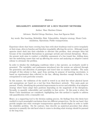
On the main initiatives promoted by the U.S was the NCHRP Project 3−70, ”Multinodal Level
of Service for Urban Streets”. The main purpose of the study was to identify measure of services
for buses that could be directly compared with other modes of transport. Onboard surveys were
conducted on bus routes with different quality of services ( e.g., frequency, reliability, loading)
operated by five different agencies across the U.S. Customer were asked to rate their overall trip
satisfaction and to rank out of a list of 17 factor the most relevant metric which contributed to
their decision. The results can be summarized in figure 2.1.
Figure 2.1: Factors contributing most to stated overall satisfaction with a transit trip. Source:
TRB (4)
Buss passenger’s satisfaction varied significantly, even with identical trips. However, it was
possible to identify those factors which were considered as being the most important when
Marc Mart´ınez G´omez Page 12 of 81
14. CHAPTER 2. LITERATURE REVIEW AND CURRENT PRACTICES
customer were satisfied. As shown in figure, passengers consistently ranked frequency as the
most important factor, followed by reliability and waiting time.
2.3.1 The value of time
Even though that users tend to consider the price as the most relevant aspect when asked
how much their journey cost, experiences put into consideration that they also place a value
on travel time and journey quality. This arguments plays a major role when the user decides
which mode of transport is more appropriate to use.
As can be further explained in TRB (4), in public transportation such as bus transit networks
the access, transfer and waiting time are not perceived in the same manner as the in-vehicle
travel time. According to Ortuzar and Willumsen (2001) a unit of time spent during these
stages is perceived more negatively than a unit in-vehicle time. Pratt and Evans IV (2004) The
report presented in Pratt and Evans IV (2004) reinforces these principals. Analyzing different
ranges of in-vehicle, walk, initial wait and transfer time from eight U.S studies from the 1960s
to the 1990s it was concluded that walking time, for instances, could be perceived as 2.2 times
in-vehicle travel time. The results of the study are summarized in figure 2.2.
At the same time that frequency, reliability and users time show to be very meaningful when it
comes to measure quality of service, it is interesting to see how the bunching problem affects all
of them. First of all, if it is desire of the agency to provide higher frequencies to stimulate the
passengers demand, the bunching effects will be more likely so even a very small perturbation
will cause the delay to propagate over time with no opportunity to recover. Reliability, on the
other hand, is considered as the main bunching indicator and it is clear that and unreliable
system is an evident disincentive to users, so they will have to budget some extra time to arrive
at the desired time to their destinations. At the same time, this lack of reliability will cause
large gaps in service with passengers waiting long periods to take a bus. Hence, based on the
arguments stated above, it seems clear that the bunching effect is doubtless one of the causes
of lack of satisfaction within the users.
Figure 2.2: Relative values of time for different stages of a trip. Source: TRB (4)
Marc Mart´ınez G´omez Page 13 of 81
15. CHAPTER 2. LITERATURE REVIEW AND CURRENT PRACTICES
2.3.2 Reliability performance metrics.
According to TRB (5) several metrics of reliability are used in practice by transit agencies. The
most common are:
• On-time performance,
• Headway adherence (the consistency or ”evenness” of the interval between transit vehi-
cles).
• Excess wait time ( the average departure time after the schedule time).
• Missed trips (i.e., scheduled trips not made).
• Percent of scheduled time in operation (for automated systems).
• Distance travelled between mechanical breakdowns.
The first three measures listed, a part from incorporating the effects of all potential sources of
unreliability, are the most widely used so all three can be derived from tracking bus departures
at the stations. On-time performance is defined as the percent of scheduled deviations (actual
departures minus scheduled departures) that fall within a certain range (e.g., 1 min early to 5
min late). On the other hand, headway adherence is defined as the coefficient of variation of
headways (standard deviation divided by the mean). It will be seen during this chapter that
the suitability of each one depends mainly on the target frequency the network is defined at.
On-time performance
On-time performances is the most widely used reliability measure in the North American transit
systems according to Benn (1995) and Revi (2001). It is usually applied to those lines designed
to operate according to a published timetable, specially services operating at long headways
(e.g., longer than 10 min). At shorter headways, the passenger reliability perception is more
related to headway adherence, since a bus could be driving out of schedule and not be noticed
by the user because another vehicle arrives.
The main negative aspect of on-time performance as a performance metric has to do with its
subjectiveness. This is because the measure of reliability strongly depends on how ”on time” is
measured and that concept tends to vary significantly across regions and agencies. References
Benn (1995) and Revi (2001) explore further the degree of heterogeneity found on different
agencies around North America, being the most used definition of ”on time” varying from 1
min early to 5 min late. It is clear that this shortcoming could be overcome with a more
consistent and robust threshold measured by the industry. Figure 2.3 presents the different
perspectives and implications from both the users and operator depending on the degree of
on-time performance offered. In this manner, a high level of service can only be achieved by
mitigating the uncertainty associated to traffic mixed flow.
Marc Mart´ınez G´omez Page 14 of 81
16. CHAPTER 2. LITERATURE REVIEW AND CURRENT PRACTICES
Figure 2.3: Fixed-route on-time performance quality of service. Source: TRB (4)
Headway adherence
Headway adherence is considered as the most appropriate metric to measure reliability in busy
lines with short headways and strong bunching tendency. This measure is the most widely used
for those lines operated at headways of 10 min or less, particularly on surface streets.
At the same time that headway adherence is a measure of reliability, it is also the best available
measure to describe the bunching effect, that’s the reason why it would be considered in this
work as the main metric to quantify improvements in reliability in the model that will be
presented in the next chapters. According to TRB (5), headway adherence is measured as the
coefficient of variations of headway CvH, defined as the standard deviation of headways σH
(representing the range of volatility of actual headways), divided by the average (H):
CvH =
σH
H
.
Hence, it is a metric than intents to quantify the degree of variation that the fleet of buses
shows when arriving at the stations. It is also worth to notice how useful the information
displayed in figure 2.4 to quantify the quality of service offered to the users in real lines where
arrivals and departures of buses at each stations are monitored. Figure 2.4 classifies the level of
reliability offered to the users in terms of the CvH magnitude. As an illustrative example, let’s
Marc Mart´ınez G´omez Page 15 of 81
17. CHAPTER 2. LITERATURE REVIEW AND CURRENT PRACTICES
consider a line with a set of arrivals whose standard deviation goes over 75% of its average, it
would be classified as a highly unreliable network where most vehicles arrives in bunches. As
shown in the figure, CvH can also be related to the probability P that a given transit vehicle’s
headway will be off-headway by more than one-half the target headway H. This probability is
measured by twice the area to the right of Z on one tail of a normal distribution curve, where
Z in this case is 0.5 divided by CvH. In this manner, the main pitfall associated to CvH is that,
being a statistical measure, it may be difficult to explain it to stakeholders. Moreover, even for
those interested in statistics, it is a way of summarizing a distribution frequency in only one
number and that indeed implies several assumptions that, in most of the cases, does not define
the whole variability of the distribution and may be very misleading. Nevertheless, it is the
most widely used metric by far when bunching problems are present and its robustness across
lines guarantee a very useful benchmark when comparing different regions.
As it will be seen during the development of this work, CvH will play a major role in the
case application that will be analyzed, since it will be the main criteria to determine the level
of service offered, according to 2.4. In order to overcome the loss of variability information
commented above and with the overall purpose of quantifying the risk assumed by the trans-
portation agency when deciding to implement a specific policy, it will be accompanied by a full
description of the distribution generated through the model simulation.
Figure 2.4: Range and classification of different Level of Services considered. Source: TRB (5)
Marc Mart´ınez G´omez Page 16 of 81
18. Chapter 3
Model Definition
Chapter 1 and 2 presented the bus bunching problem, drilling down into the research activity
carried out so far by the researching community and covering the current practices deployed in
reality by transportation agencies. This Chapter, on the contrary, will focus on introducing the
mathematical framework to model the physics considered in order to address the bus bunching
problem in a real context. In is important to emphasize that the purpose of the model is to be
a supporting tool in order to analyze real scenarios and make decisions, that’s the reason why
different management strategies that can be feasibly deployed in actual networks will also be
implemented.
While the majority of studies examining transit performance are empirically based it is also
true that some numerical tools have been used to simulate the bunching phenomena. The
problem is that, according to the author’s knowledge, only a few of them are constructed
assuming the hypothesis required to take into consideration the considerable randomness that
characterizes a bus transit network. Analyzing the bus bunching’s root causes, It is clear that
deterministic models are not capable of representing the huge variability associated to buss trips
in busy routes. Based on the idea that a buss line is exposed to different exogenous disruptions,
experiences put into perspective that the stochastic nature is essential if the model intends to
be reliable enough under real situations. That’s the reason why passenger’s boarding/alighting
processes and traffic interactions must be adequate defined. Hence, the model presented in
this work follows a similar structure to those introduced in Daganzo (2009), Daganzo and
Pilachowski (2011) and Estrada and Mension (2015) when it comes to describing the physics
and bus trajectories evolution. While Daganzo (2009) considers stochastic hypothesis when
defining the dynamics equations, the article does not provide details or studies on how the
equations could be applied to a real network and it is much more focused on the qualitative
approach to reduce the bunching effect. On the other hand, Estrada and Mension (2015) builds
a detailed model and applies it to an ideal network, showing relevant improvements in terms
of performance. Despite the scope of the model is very robust and can be easily adaptable to
real bus line conditions, the assumptions regarding passenger arrivals and vehicle travel time
are both deterministic, being far away from real conditions. Hence, the model presented in
this work is based on similar assumptions, but relies on additional hypothesis that improve the
Marc Mart´ınez G´omez Page 17 of 81
19. CHAPTER 3. MODEL DEFINITION
context of the model and spread its range of application.
Additionally and despite the fact that the model aims to idealize the real behaviour of a
bus transit network, it must not be neglected that it is meant to be used under operational
conditions so, with the purpose of making in it flexible and useful, a trade-off between too level
or detail and easiness of application is assumed, focusing only on those parameter that, after
conducting a literature review, the author considers as essential to characterize the bunching
behavior. It is important to emphasize that the main objective of the model is being able to
create different scenarios, understanding the effects of the different variables and being able
to test their implications. Without a detailed enough model it is complicate to calibrate or
predict how a system will respond but when it comes to a decision-making model it is neither
advisable to get lost in supporting details that deviate from the big picture. As will be shown
in this chapter, a balance has been pursued.
3.1 Background and context
The scenario considered is composed of an ideal bus line of length 2L like the one showed in
3.1. The route presents 2N stops and the distance between stop s and s+1 is assumed to be ls.
Therefore, each station is labelled as s = 1, ...2N. The total number of buses J operating along
the route are defined as j = 1, .., J and each one of them is supposed to travel roundtrip. In
this manner, the bus j+
= j +1 and the bus j−
= j −1 are considered to be at rear and at front
of bus j respectively. The model considers that buses can operate the line several times, hence
the stops are labeled as s = 1 + (K2N), 2 + (K2N), ..., N + (K2N) where K ∈ (0 ≤ k ≤ ∞) is
an integer number that stands for the cycles completed by the fleet. By following this notation,
stop pairs s = 1 + K2N; s = 2N + K2N and s = N + K2N; s = N + 1 + K2N represent
the same physical point (terminal or headers)but reflects to bus stops from different service
directions.
Figure 3.1: Bus route scheme. Source: Estrada and Mension (2015)
It is important to emphasize that according to the model construction, the total number of
buses deployed J is considered to be fix once the target headway H has been defined. This
Marc Mart´ınez G´omez Page 18 of 81
20. CHAPTER 3. MODEL DEFINITION
relationship is established by equation 3.1
J =
2N
s=1[Tt,s + Ts,s + ψs] + αA + αB
H
, (3.1)
where relevant variables such as the travel time Tt and the time spent at stops Ts are introduced.
Additionally, there are other important parameters that influence the number of buses and these
depends on the management policy established by the transport agency, ψ, αA and αB. These
terms stand for the slack time introduced in schedule to tackle the potential disruptions, the
most widely used strategy against the reliability problem. ψ refers to holding time at the
headers defined and regulated by the workers’ union while αA and αB are buffer time inserted
on purpose by the agency. The main differences are that ψ cannot be removed from schedule
and is not a variable the operator can adjust. On the other hand, both αA and αB are set by
the agency in their constant pursuit of reliability. While this extra time allows buses ahead of
schedule to recover their headway target revealing a useful strategy to fight against bunching
it is however an important economical burden for the agency, so as equation 3.1 shows it
significantly increases the operational fleet J. Again, the Agency makes decision under the
trade off between cost and level of service.
Another important remark worth to highlight is the subindex s accompanying the variables
within equation 3.1. This definition arises from the idea to make the model flexible, setting
Tt and Ts as changeable variables from station to station. As has been explained above, the
stochastic behavior plays a very important role when it comes to idealize the bunching problem
and it is very important to base our hypothesis on it. Moreover, this formulation also enables
to use the model into real lines where distance between stops are not considered equal.
3.2 Passengers’ boarding and alighting process
The idealized bus trajectories appearing along a route are idealized in figure 3.2. As can
be observed, the trip is broke into different parts: (1) and (7)stands for the time spent to
travel between two following stops; (2) and (6) for the time spent decelerating and accelerating
respectively; (3) and (5) for the time spent on opening and closing doors. Hence, following
the nomenclature above and with the purpose of simplifying the model a discrete approach
is presented. The time spent accelerating and decelerating is neglected and the trajectory is
approximated by a piecewise line with only two speeds: V when travelling and 0 when dwelling.
As will be explained in the next sections, the path of the bus is segmented into two main parts:
time spent travelling between stops Tt and time dwelling at stops Ts.
3.2.1 Travel time (Tt)
Travel time (Tt) is composed of two additive parts represented on equation 3.2 for an specific
bus j. While the former is fully deterministic and depends on the length between stops ls
Marc Mart´ınez G´omez Page 19 of 81
21. CHAPTER 3. MODEL DEFINITION
Figure 3.2: Parts of a trajectory. Source: Pilachowski (2009)
and the speed of the bus V , the second one υ represents a random noise whose purpose is to
introduce a source of uncertainty into the system.
Tt(j, s) =
ls
V (j)
+ υ. (3.2)
Despite the fact that V may be considered a constant speed it depends on j in equation 3.2.
This is due to the fact that later on in next sections an adaptive and dynamic strategy based on
relative velocity between buses will be introduced as a measure to tackle the bunching problem
and that will induce changes on the variable. Moreover and as will be discussed in more depth in
the next sections, since the trajectory definitions neglect disruptions because of traffic signals
during the trip from station to station, the physical interpretation of that velocity V is set
somewhere between cruising and commercial speed, the two main variable that are tracked in
practice.
The main assumption relies on the second term of equation 3.2 so an adequate distribution
function must be chosen. Daganzo, who followed a very similar approach to account for un-
certainty in travel time in Daganzo (2009), proposes to consider the noise factor as normal
with µ = 0 and a certain σ. On the other hand, according to real experience buses have a
stronger tendency to delay than to run ahead as a result of traffic and exogenous disruptions
along their trips. This trend suggest an asymmetric distribution with a longer tail in the right
hand side. Apart from that, the distribution must be continuous and adaptable to different
lines and situations. Based on these facts and because of its easiness appliance under highly
Marc Mart´ınez G´omez Page 20 of 81
22. CHAPTER 3. MODEL DEFINITION
uncertain environments the final proposal is a triangular distribution function(see Caplice and
Gabris (2015) for further details). This distribution is characterized by only 3 physical values,
the most common, the maximum and the minimum. In this manner, the fact of being able to
define an upper and lower bound is another advantage since that will provide stability to the
model.
The next decision has to do with establishing the maximum and minimum value. These bounds
are defined as a percentage of the deterministic travel time Tt(j, s) = ls
V (j)
. Based on the stronger
tendency to delay and with the objective to avoid very low travel time values, the lower bound is
considered as 0.5Tt and the upper as 1Tt. Hence, this formulation enables to establish a bounded
relation between the maximum deviation suffered by a bus and its deterministic travel time.
In this case, the assumption would imply that, at maximum and minimum, a bus could take 2
and 0.5 times the deterministic travel time introduced in 3.2 respectively.
The definition and distribution of υ after 10,000 simulations can be observed in figures 3.3 and
3.4. As long as simulations are run the shape of the distribution in 3.4 will be smoother and
closer to 3.3. This example shows the powerful application of Monte Carlo simulation approach.
Marc Mart´ınez G´omez Page 21 of 81
23. CHAPTER 3. MODEL DEFINITION
Triangular.png
Figure 3.3: Triangle distribution definition. Source: The author
Triangular.png
Figure 3.4: Frequency obtained in 10,000 simulations. Source: The author
Marc Mart´ınez G´omez Page 22 of 81
24. CHAPTER 3. MODEL DEFINITION
Figure 3.5: Triangle distribution. Source: Caplice and Gabris (2015)
Despite the fact that the Triangular distribution is one of the most widely used assumptions
when dealing with uncertainty under the Monte Carlo Simulation framework it is worth to
mention that is only a first good way to get a sense of a distribution. It is typically used in
those environments where data is really scarce because the only information required to define
it is to remember extreme and common values. Once this formulation is implemented into a
real line, these extreme values should be calibrated with historical data to propose a tailored
solution.
Marc Mart´ınez G´omez Page 23 of 81
25. CHAPTER 3. MODEL DEFINITION
3.2.2 Time dwelling at stops (Ts)
The time dwelling at stops it is a crucial component that plays a very important role in causing
the bus bunching problem. It has been shown in experimental studies and research that the
high variability and randomness regarding the time a specific bus stays at stations boarding
and alighting passengers is the main reason that propagates an external disruption within the
system and end up causing meaningful service gaps. It is clear, hence, that the definition of
the dwelling time (Ts) in the model must be aligned with stochastic hypothesis. That time can
be splitted into different stages such as the time spent on opening and closing doors (toc) and
the time passengers boards or alight the vehicle (TBA. This phases are described in equation
3.3 and intent to describe components (3),(4),(5) from figure 3.2.
Td(j, s) = toc + Tba. (3.3)
Despite the fact that both of them present variability, with the overall purpose of not overcom-
plicating the model and due to the fact that the effect of TBA further outweighs the one from
toc, the model will place all the uncertainty in TBA while toc will be assumed as a deterministic
number. On the contrary, based on the mathematics of the model that will be described in the
next sections, this TBA is calculated as a function of the numbers of passengers that boards
and alights at specific station s. That’s the idea why, before defining that relation, it is needed
to identify passenger flows at each station. Hence, the upcoming subsection is focused on de-
scribing the rational behind passenger’s boarding and alighting process. As will be explained,
this approach relies on building probability distribution functions from empirical data obtained
from origin and destination matrix MOD.
Passenger’s boarding and alighting processes. The origin/destination matrix MOD.
Let’s consider that the line analyzed has an hourly demand of Λ pax/hr. The matrix displayed
in figure 3.6 describes an idealized and normalized passenger flow matrix of a line formed of
20 stops per direction. This matrix does not attempt to be representative of an specific line.
Instead, is a generalized profile of what experience shows that can be expected to observe in a
general line. In this case the number of station have been set up to 20 per direction since, as
will be seen in Chapter 3, the model will be test on a line composed of 20 stations. In case of
proposing another line this same profile can be easily extrapolated or obtained from real data
collected either from on-board origin destination surveys or boarding and alighting counters. In
this manner, any travel generated during an interval of time will have an origin and destination
whose probability to occur are described on figure 3.6. Hence, once this percentage matrix is
brought to probabilistic terms the following expression is fulfilled: S
i=1
j=1
MOD(i, j) = 1.
Marc Mart´ınez G´omez Page 24 of 81
26. CHAPTER 3. MODEL DEFINITION
Figure 3.6: Matrix MOD.Percentatge of passenger trips among stops. Source: The author
First of all the analysis will be focused on assigning this Λ flow of passenger to the different
stations. According to matrix MOD, each station s will have the following rate of arrivals
(Pax/hr):
λs =
S
j>s
MOD(s, j)Λ. (3.4)
Hence, this definition leads to a global expected boarding passenger’s distribution like the one
displayed in figure 3.7. As can be observed, station 5 is expected to be the station where a
maximum number of passengers are generated for a given time considered. By performing this
analysis, each station has been assigned with a specific passengers flow λs.
Marc Mart´ınez G´omez Page 25 of 81
27. CHAPTER 3. MODEL DEFINITION
Figure 3.7: Distribution of the expected departures for a given directional flow. Source: The
author
Once this passengers’ flow has been generated at each station s, it has to assigned to another
station s∗
> s. This process is conducted by following the information provided by the origin
destination matrix MOD. The way of addressing the problem follows the same idea as in the
passenger’s boarding process. The purpose is to define a specific alighting distribution for each
station s∗
> s. This probability can be obtained with the following expression:
P(s∗
/s) =
MOD(s, s∗
)
S
j>s MOD(s, j)
where s∗
is higher than s. (3.5)
When this probability is calculated for all stations the distribution of the expected passenger’s
alighting process for a given directional flow is the observed in figure 3.8. Thence, it can be
shown that the vast majority of landing processes are expected to take place at the last stations
of the route.
Marc Mart´ınez G´omez Page 26 of 81
28. CHAPTER 3. MODEL DEFINITION
Figure 3.8: Distribution of the expected arrivals for a given directional flow. Source: The
author
Additionally, the MOD matrix also enables to obtain the expected distribution of the passen-
ger’s occupancy regarding one bus that drives along that specific direction. Combining the
information from figure 3.7, 3.8 and figure 3.9. This figure display the occupancy of the bus as
a % of demand over a unitary target headway.
Marc Mart´ınez G´omez Page 27 of 81
29. CHAPTER 3. MODEL DEFINITION
Distribution.png
Figure 3.9: Expected occupancy as a percentage of expected passengers. Source: The author
Consequently, the expected occupancy of a bus follows a symmetric shape that characterizes
by most of the passengers boarding at the beginning and alighting at the end of the line. As
will be discussed in the following examples, these distributions will be the base that will be
used in order to implement into the model the passengers’s boarding and alighting processes
from an stochastic point o view. Therefore, once the passenger’s are generated and assigned,
dwelling time as stops can be calculated.
Another important remark worth to mention is that, while these distributions are the ones
expected, the Monte Carlo simulation tool will help to introduce their range of variability and
randomness that characterize these processes in the real world. The power and advantage of
this matrix approach is that is very easy to obtain for an specific line either by conducting
surveys or using data collectors, so can be easily adapted an extrapolated to a specific line
desired.
Boarding and alighting time (TBA)
With the goal of defining the dwelling time spent on stations in the model, the information
from MOD has to be translated from probabilistic terms into absolute number of passengers.
In order to determine the number of passengers boarding a bus j a Poisson distribution is
suggested. Since The λs definition described in equation 3.4 gives the flow of passengers at
Marc Mart´ınez G´omez Page 28 of 81
30. CHAPTER 3. MODEL DEFINITION
station s so the average passengers expected is calculated as:
[Ta(j, s) − Ta(j − 1, s)]λs,
where Ta(j, s) and Ta(j − 1, s) are the real headway of the bus j and the bus ahead j − 1.
Despite the fact that mathematical expressions for Ta(j, s) and Ta(j − 1, s) will be introduced
in the next section, what it is relevant is that their values are known once a bus arrives at the
station. Hence, the numbers of passengers boarding at a stop s for each bus j is described as
a Poisson random variable and fulfills:
B(j, s) = Poisson [Ta(j, s) − Ta(j − 1, s)]λs. (3.6)
It is important to point out several remarks here. First of all that the real headway [Ta(j, s) −
Ta(j − 1, s)] will tend to be the target headway H while the system is in equilibrium and, as
long as one external disruption takes places and propagates upstream and downstream the
system, it will tend to deviate little by little. Another important aspect is that, as will be
seen in the next section where the motion equations will be described, in order to evaluate this
expression j must be higher than 1, what from a physical point of view means that, the first
bus running from the terminal will have no references with the bus at front. We will also see
in the next section how, since this case has to start somehow, the target headway H will be
assigned instead.
Once these passengers have been generated, each one of them have to be assigned to the station
where they will alight. In this case and by following the expression 3.5 a passenger boarded at
s is allocated at s* according to a discrete probability function P(s, s∗
) that :
P(s∗
/s) =
Mod(s, s∗
)
S
j>s MOD(s, j)
where s∗
is higher than s,
By following this expression the number of passengers alighting at a specific station s for
each bus j (A(j, s))can be calculated. This probability function will lead to a global landing
distribution of passengers that will tend to the one from figure 3.8 but again, by contemplating
the uncertainty of a random variable. For instances, figure 3.10 shows the specific distribution
for the case of s = 7.
Marc Mart´ınez G´omez Page 29 of 81
31. CHAPTER 3. MODEL DEFINITION
Figure 3.10: Alighting probability of a passenger boarding at station s=7. Source: The author
In this manner and going to the aspect governing this section, once the number of boarding
and alighting passengers have been defined, equation 3.3 can be completed. By following the
same nomenclature the dwelling time is defined as:
Ts(j, s) = max[γB(j, s); βA(j, s)], (3.7)
where γ and β are respectively the unitary time per passenger associated to boarding and
alighting the vehicle. It is worth to notice that this definition of Ts implies independent unitary
times between users. Moreover, despite the fact that this time could also be defined as a random
variables in order to take into account the uncertainty regarding the payment method or the
accommodation of disable people, it has been considered deterministic in the model. Despite
the fact that these assumptions could be discussed in greater detail, according to the author’s
opinion, they focus on supporting details instead of the big picture, which is the passengers’
generation process.
Key takeaways
Arrived at this point it is worth to summarize and gather all the information provided in this
section regarding the passengers’ boarding and alighting processes. Hence the procedure can
be summarized by following the next steps:
• The idea is that, in reality, these processes present a considerable uncertainty and vari-
ability, being one of the main underlying causes of bus bunching. Hence, if the goal is
to define a model that idealizes a bus transit network from a reliable point of view, the
processes must be defined accordingly.
• The framework proposed in this work relies on an origin/destination matrix MOD for a
typical line with a given demand flow Λ as a way of determining which arrival rates will
Marc Mart´ınez G´omez Page 30 of 81
32. CHAPTER 3. MODEL DEFINITION
have each one of the stations (λs)and, once generated the passengers, where they will
alight. The main advantage of this method is that tailored Mod can be obtained in case
of being analyzing a specific line.
• As long as this information is generated during the trip of each bus j through each station
s, the time dwelling at stops (Ts(j, s)) can be calculated and, consequently, the different
trajectories of the buses can be characterized.
3.3 Motion Equations
The passenger’s boarding and alighting process described in the past section is the key point
required in order to calculate the different variables that will end up defining the bus trajectories
within the line. Once this process has been properly characterized, dwelling time at stops is
calculated and the whole trajectories are drown up.
Therefore, the model presented relies on a discrete procedure where all relevant internal vari-
ables and outputs are calculated for every value of j and s, being j and s fixed buses and
stations respectively. Before being in conditions to proceed with the computational scheme,
the first step concerns the definition of all the inputs interacting in the model, displayed on
table 3.1:
Variable Description
S Number of Stops in one direction
Λ Flow of passengers (pax/hr)
L Length of stops (m)
v Cruising speed (km/hr)
H Targeted time headway(min)
φ Lay-over time at terminals or headers (min)
α Recovery time to meet schedule (min)
α Recovery time to meet schedule (min)
γ Boarding time per passenger (s)
β Alighting time per passenger (s)
C Bus Capacity
K Number of round trips
Table 3.1: Inputs required to conduct the simulation
The integer parameter K stands for the number of round trips that the simulation will last.
Hence, these variables are able to generate different outputs that are stored in a range of different
matrixes during the passage of the simulation, whose size is MJx[2S+(2KS)]. By analyzing the
nature of the inputs, it is quite reasonable to segment them according to those intrinsically
defined by the physical line, such as the number of stops and their length, the passenger demand,
the speed or the bus capacity and those that can actively be managed by the transportation
agency: The target headway or the recovery time to meet the schedule.
Marc Mart´ınez G´omez Page 31 of 81
33. CHAPTER 3. MODEL DEFINITION
In this manner, the discrete framework considered in the simulation is based on isolated buses
that cover all the stations along both directions. All these buses receives and alights a specific
number of passengers at each station (B(j, s) and A(j, s)) based on the relationship described
in equation 3.6 and their corresponding alighting probabilities. Once a bus has completed the
roundtrip, the simulation moves to the next one whose headway is calculated as the differences
in arrival times with the bus ahead [[Ta(j, s) − Ta(j − 1, s)]. Since the first bus has no bus
ahead, the model considers that during its first trip it will be boarding passengers according to
the perfect headway H, relying on a Poisson distribution like the one defined in equation 3.4,
but this time with an expected number of passengers of Hλs. Consequently, as long as the the
J buses have covered the whole line the simulation moves to the first bus again by using a loop
along the number of roundtrips (K). This time the bus j=1 will be capable of running at a
headway Ta(j, s) − Ta(J, s − 2KS).
Thereupon, a set of steps can be defined when it comes to computing the code. They all are
summarized in the next few points:
• Fleet determination to meet H.
• Outputs calculation of bus j at stop s.
• Loop on number of station 2S.
• Loop on number of buses J.
• Loop on number of roundtrips K.
Once the inputs in table 3.1 have been defined, the number of buses J required to meet that
headway H can be calculated by using equation 3.1 described in section 3.1. Equation 3.1
considers again the trip of an isolated bus that covers all the stations along one direction. This
bus, in the same manner than bus j=1 from the simulation, is assumed to receive passengers at
a perfect headway H. Since both travelling time Tt and dwelling time Ts are random and their
instances tend to change from simulation to simulation, value J is calculated as the number
that would meet the schedule 95 of the times on sample of 100 simulations. This is aimed
to idealize a level of service policy selected by the transportation agency, who goes through a
decision making process based on its operational data from the line. However, as a result of
the interactions between buses during simulation time, the time a bus spends on completing a
roundtrip may increase significantly, being J buses unable to meet the target schedule. This is
the reason why this 95 percentile is defined, with the purpose of neutralizing the conservative
assumption of running at perfect headway in an isolated manner.
The different outputs are calculated for every bus j at each station s. First of all and by
following the expression provided on 3.3 and 3.6, passengers are generated and allocated to get
off at specific station based on the probabilistic functions described in section 3.2. Those pas-
sengers that cannot be picked up because of capacity constraints within the bus are stored with
their assigned destination and, once the next bus passes for that station, are boarded if possi-
ble(otherwise stored again in the system.) Afterwards, the loops through all the stations and
Marc Mart´ınez G´omez Page 32 of 81
34. CHAPTER 3. MODEL DEFINITION
Variable Units
B(j,s) Boarding passengers of bus j at station s
A(j,s) Alighting passengers of bus j at station s
O(j,s) Occupancy of bus j from s to s+1
E(j,s) Excess of passengers unable to board at bus j at station s
Ta(j, s) Arrival time of bus j at station s (s)
Ts(j, s) Dwelling time of bus j at station s (s)
Td(j, s) Departure time of bus j from station s (s)
V (j, s) Velocity of bus j from s to s+1 (m/s)
Table 3.2: Outputs considered within the simulating
all the buses are programmed in the code, completing a full roundtrip where all the meaningful
variables to define the situation of the lines are recorded. Thence, the relevant outputs consid-
ered will be introduced through the description in the next section but can be summarized in
3.2. These outputs can also be segmented into two categories, those that refers to passengers
generation, such as boarding and alighting passengers (B and A), Occupancy (O) or excess
of passengers (E), and those that stands for time variables: Arrival, dwelling and departure
time (Ta, Ts and Td). While the formers are generated through the origin/destination matrix
(MOD)and are very useful to evaluate operational issues such as capacity and cues problems,
the later enable to establish the trajectories of the buses and their path along the route.
As can be observed in table 3.2, all variables refer to indexes j, s since as has been mentioned
earlier, the simulation will display matrices variables of size J[2S + (2KS)]. Hence, with this
previous explanation and the context explained on section 3.3, the following step regards the
precise mathematical relationships to convert inputs from table 3.1 to outputs from 3.2.
3.3.1 Mathematical equations
As has been presented above, the code proposed to conduct the simulation relies on a series
of loops with regard to the stations, the buses and the number of roundtrips. Almost all the
trips can be generalized within an aggregated mathematical expression but, as always, there
are a few exceptions that are worth to mention. These exceptions have mainly to do with
the first and last bus (j = 1 and J) and the first station of the line once a bus leaves the
terminal to start a new trip along one direction (s = 1 + 2KS and s = S + 1 + 2kS). Thence,
the procedure follows to describe the mathematical relationships will consist on introducing
firstly the generalized expression and, afterwards, drilling down into details commenting how
the definition of the code allows to deal with the different exceptions.
Let’s consider hence a general bus that starts its roundtrip once the system is already warmed
up and with at least one bus ahead as a reference. Since the bus ahead could not board all
the passengers due to capacity problems, suppose that those passengers have been stored in
mE(j − 1) with their respective destinations. Its trajectory and its passengers information can
be calculated by following the next mathematical framework:
Marc Mart´ınez G´omez Page 33 of 81
35. CHAPTER 3. MODEL DEFINITION
Loop on number of roundtrips k=0,...,K;
Loop on number of buses j=1,...,J;
mo,d(j) = mE(j − 1); (3.8)
Loop on number of stops s=1,...,2S+2KS ;
Ta(j, s) = Td(j, s − 1) + Tt(j, s) = Td(j, s − 1) +
L
V (j)
+ υ; (3.9)
B(j, s) = Poisson [Ta(j, s)−Ta(j −1, s)]λs.+
S
l=1
mod(s−2KS, l) = B +
S
l=1
mod(s−2KS, l);
(3.10)
mod(s, s∗
) = mo,d + B (j, s)P(s∗
/s) = mo,d + B (j, s)
MOD(s, s∗
)
S
j>s MOD(s, j)
where s∗
is higher than s;
(3.11)
A(j, s) =
S
l=1
mOD(l, s − 2KS); (3.12)
E(j, s) = max[O(j, s − 1) + B(j, s) − A(j, s); 0]; (3.13)
mE(s, s∗
) = E(j, s)P(s∗
/s) = E(j, s)
MOD(s, s∗
)
S
j>s MOD(s, j)
where s∗
is higher than s; (3.14)
B(j, s) = B(j, s) − E(j, s); (3.15)
O(j, s) = min[O(j, s − 1) + B(j, s) − A(j, s); C]; (3.16)
Ts(j, s) = max[γB(j, s); βA(j, s)]; (3.17)
Td(j, s) = Ta(j, s) + toc + Td(j, s). (3.18)
The mathematical equations follow a sensible process respecting the sequence of events that
take place in physical reality. The first computation is conducted before stating the number of
stops loop in 3.14 and stands for establishing within the experimental passenger matrix of bus j
(mod(j)) the boarding and alighting information regarding the excess passengers that could not
board bus j−1 (mE(j−1)). With this information, bus j has additional passengers to board and
alight, apart from those belonging to its respective demand. Equation 3.9 enables to calculate
the arrival time Ta based on the departure from the last station and its corresponding travel
time described in equation 3.2. This component accounts for the traffic uncertainty during the
trip by incorporating the parameter υ. Since the bus it’s already in the stop, it will have to
pick up the passengers with regard to the flow at that station λs and its headway with the bus
ahead [Ta(j, s) − Ta(j − 1, s)], but also the excess mE(j − 1) from last bus. This calculation is
Marc Mart´ınez G´omez Page 34 of 81
36. CHAPTER 3. MODEL DEFINITION
performed in equation 3.10. The next step in 3.11 refers to the allocation of this new passengers
B , which is done according to the discrete pdf defined in Chapter 3. This allows to update
the matrix mo,d. In order to calculate the number of alighting passengers at stop s, equation
3.12 is introduced. Nevertheless and as a result of the capacity constraint, there may be an
excess of passengers into the bus that is calculated in 3.13 by using the occupancy from the bus
ahead O(j, s − 1). At the same time, this excess is allocated to a specific station in equation
3.8, creating the excess matrix mE(j) that will be used by the next bus at rear j = j + 1.
Consequently, the number of boarding passengers requires to be updated not to double count
the excess passengers according to 3.15 and the occupancy is calculated based on 3.16. Once
these processes have been carried out, trajectories and times can be set up. The dwelling time
spent at the station is calculated in equation 3.17, being γ and β the unit passenger time on
boarding and alighting respectively. To wrap up, the time leaving a station s is calculated on
3.18, where toc refers to time spent on closing and opening doors.
This process is thereafter programmed on a loop for all the station, for all the buses and for
all the number of roundtrips desired until the end of the simulation. However, as has been
remarked on the first lines of this section, these set of equations works for almost all the trips
but the first and the last bus (j = 1 and j = J) and first stations of each direction (s=1+2KS
and s=S+1+2KS). In these cases little modifications must me made to go along. Let’s start by
the calculation of arrival time (Ta) at the headers, where an additional case must be identified,
taking into account the slack times and the lay-overs. If the arrival of bus j and its passenger
alighting process at the ending stop is made without a significant delay, it is advisable that
this bus j may start running in the opposite direction trip of the route satisfying a perfect
schedule that supposes that a bus should depart the terminal each H units of time. Hence,
KJH is added to the first cycle’s arrival time of the bus at the terminal (Ta(j, s − 2KS)). On
the other hand, if the bus is remarkably delayed, there would not be enough slack in the header
to compensate that delay, and the bus will start its route with a deviation from the target
schedule that will propagate in the opposite direction. Consequently, equation 3.9 should be
segmented into the following expression 3.19:
Ta(j, s) = max(Td(j, s − 1) + φ; Ta(j, s − 2KS) + KJH) if s = 1 + 2KS or s = S + 1 + 2KS;
Ta(j, s) = Td(j, s − 1) + Tt(j, s) = Td(j, s − 1) +
L
V (j)
+ υ. Otherwise. (3.19)
The second exception refers to the fact that, when bus j = 1 starts its trip at the headers
in one direction, equation 3.10 is no longer acceptable since the headway comparison must be
done with the last bus j = J. Thereupon and in order to not affect the code, this headway is
substituted by [Ta(j, s) − Ta(J, s − 2N)] according to the expression displayed in 3.20
B(j, s) = Poisson [Ta(j, s) − Ta(J, s − 2N)] ∗ λs. +
S
l=1
mod(s − 2KS, l) if j = 1;
Marc Mart´ınez G´omez Page 35 of 81
37. CHAPTER 3. MODEL DEFINITION
B(j, s) = Poisson [Ta(j, s) − Ta(j − 1, s)] ∗ λs. +
S
l=1
mod(s − 2KS, l) Otherwise. (3.20)
Once these little tweaks are introduced into the equations, the model only needs the insertion
time of each vehicle
Ta(j, 1) = (j − 1)H for all j,
and the assumption that the first roundtrip of bus j = 1, who has no references with any bus
ahead, receives passengers according to the perfect headway H in equation 3.19. This assump-
tion has a lot in common with real conditions since the first bus of the day will cover its first
trip without any direct disturbances nor reference regarding the bus ahead. Despite considering
this assumption, it is important to highlight that the model takes into account the potential
external disruptions caused by the travel time betweens stations and the passengers’boarding
and alighting processes, since are still defined as random variables.
Another important remark worth to mention has to do with equation 3.11 and 3.8. In the set
of equations describing the model it seems like the passengers generated and those in excess
(B and E) are assigned based on the fix probability described by equation 3.5. However,
what is actually done is that the passengers are assigned with regard to a simulation of that
discrete probability distribution function. This is a significant different procedure since this
simulations accounts for all the uncertainty within the alighting passengers and does not rely
on deterministic numbers such as the similar example reported in Estrada and Mension (2015).
Hence, with the definition of these motion equations, the model is capable of characterizing
properly all the trajectories for all the buses as well as other relevant variables such as the
bus occupancy in each trip, the boarding and alighting passengers at each stop or the cue
that generates at specific station as a result of the capacity constraint ”C”. As will be seen in
section 4 where the model is tested on an ideal line, these definitions idealizes very adequately
the operational process of a real line and the bus bunching problem, affecting the level of
service perceived by the passengers. Therefore, the next steps will aim to introduce into the
model the control strategies discusses qualitatively in section 2. These strategies include the
holding/buffer time introduced into the trip at the headers to allow delayed buses to recover the
adherence and, lastly, an adaptive strategy based on relative velocity between buses in order
to alleviate the reliability problem along the trip.
3.3.2 Controlling strategies
The model developed in the last subsection is based on the situation where agencies do not
assume any proactive behavior with regard to maintain the target headway and overcome
bunching tendency. By following the equations provided in the last subsection, the only control
mechanism that is playing a role is the lay-off time at the headers. This lay-off time, however,
is enforced by the drivers’ union and has nothing to do with the operator.
Marc Mart´ınez G´omez Page 36 of 81
38. CHAPTER 3. MODEL DEFINITION
On the other hand and as has been discussed in the literature, the usual practice deployed by
worldwide agencies consists on introducing additional holding/buffer time into the bus trip at
the headers or terminals with the purpose of allowing delayed buses to recover the adherence
and meet the target schedule. This slack time is defined with the parameter α described in
3.1 and, despite the fact that can be ideally introduced into stations along the route, the usual
practice and the one contemplated in the model is to only introduce it at the headers, because
of its easier deployment. As has been discussed in section 1, this strategy has been widely
used in many lines across different countries with positive results. Nevertheless, it presents
important pitfalls that maintain the agency struggling to offer a reliable service.
The main problems is that this controlling strategy is not adaptive since the slack times α
does not depend on the target headway H. The strategy enables delayed buses to recover
at the headers but cannot guarantee the adherence when a relevant disruption takes place
within the system, propagating it along the opposite direction of the route. Besides, it’s an
unproductive allocation of resources for the agency because it adds more buses into the line
regardless of whether or not these buses deviate from the targeted headway. Hence, the idea of
this section is to present a dynamic complementary strategy that can be adjusted and deployed
not only when the bunching effect takes place, but also when is arising in order to prevent it.
The framework is very similar to that proposed in Daganzo (2009) and Estrada and Mension
(2015), relying on an adaptive velocity of the buses depending to what extend they are running
behind or ahead of schedule with the bus at front.
Adaptive strategy.
This dynamic strategy is based on real-time headway monitoring of bus arrivals and departures
at stops, a technology that has emerged very strong and is starting to be deployed in busy bus
network lines with successful results. The idea is very simple and relies on the fact that the
driver is aware of his real headway with the bus ahead each time that the bus departs from each
station and, depending on wether is delayed or running ahead, he slightly modifies his velocity
with the goal of reaching adherence to target headway H. Hence, the purpose form this point
on is to idealize this physical idea into a mathematical expression that can be introduced into
the model.
Equation 3.21 evaluates the real headway of a bus j at stop s with regard to the bus j − 1
ahead. In this manner, if is > 0 it can be concluded that bus j is falling behind schedule and
on the contrary, running ahead, if is < 0. It is important to notice that this variable can be
easily calculated during the journey of a bus that incorporates monitoring technology and can
be updated from station to station.
(j, s) = Ta(j, s) − Ta(j − 1, s) − H. (3.21)
Hence, this strategy is based on the knowledge provided to the driver in order to adjust his
velocity in such a way that seeks to establish the perfect headway adherence. The motion
law that describes the implementation is defined on equations 3.23 and 3.22. This law is
accompanied by a parameter κ whose purpose is to define how sensitive are the buses to
Marc Mart´ınez G´omez Page 37 of 81
39. CHAPTER 3. MODEL DEFINITION
modify their current velocity, taking into account that in some traffic conditions that must be
unfeasible. Accordingly, when bus j is running delayed from bus j−1 it is advisable that this bus
operates at speed above the maximal value V in order to reestablish the target time headway.
This situation is presented in equation 3.22. However, when bus j presents a parameter < 0 it
means that is running ahead with regard to the bus at front and its driver should be aiming to
run at the maximum cruising speed V . Equation 3.23 refers to this second situation. In both
situations the speed of the buses is modified proportional to the difference from real headway
and perfect headway and, this proportion is determined by the parameter κ. As it is reported
in Daganzo (2009), the dimensionless parameter κ stands for the marginal increase in expected
bus delay caused by a unit increase in headway. The idea is to add or reduce the exact deviation
from headway to the trip between stations, with κ defining how fast this recovery is. Therefore,
if κ → 1 when a bus is running ahead, the headway at the next station will tend to be the
perfect headway H but to the detriment of remarkably decrease the velocity of the system.
Otherwise, if κ → 0, the modification on the speed will be meaningless and it will take a large
number of stops to reach that equilibrium. This parameter should range from 0 to 1 and, when
applied to a real line, should be calibrated in order to establish how responsive or successful a
bus may be when it comes to modify his velocity in that specific traffic environment. It is also
important to remark that, despite this work will try to simulate rush hour condition, the value
of this parameter will present an important variation across different day hours. Probably the
value will be close to 1 at midnight and very little at peak hours, specially when the bus is
trying to speed up its rhythm.
V (j, s) = min[
L
L
1.2V (j,s)
− κ
; V ] If > 0 and [
L
V (j, s)
− κ ] > 0; (3.22)
V (j, s) = max[
L
L
V (j,s)
− κ
; 0.6V ] If < 0 and [
L
V (j, s)
− κ ] > 0. (3.23)
As can also be seen in the equations, there are physical bounds that are imposed in order to
constraint the changes in velocity. The model considers that buses cannot run at a velocity
higher than 1.20V . This assumption represents real conditions, because the velocity is con-
strained by both traffic and legislation. it is important to highlight the fact that the velocity
considered in the models stands for that one used by the bus to travel from station to station,
taking into account the traffic disruptions and traffic circles but not the dwelling time spent
at stops. Since this velocity ranges somewhere between cruising and commercial, it may be
higher than V . At the same time, when the bus intents to slow down, a maximum decrease of
that velocity is assumed since is very unrealistic to think that the complex traffic environment
where a bus operates will enable to run slower. The assumption of this model is to consider a
minimum velocity around 0.6V in order to guarantee the convergence and equilibrium of the
equation. Nevertheless, in the same manner has the parameter κ,it should be calibrated when
the model is applied to a specific line where historical data is available. In this case and as will
be explained later on when the application case is introduced, these values have been selected
as a first realistic approximation due to the fact that both data and time were very scarce to
propose a more realistic approach based on calibration techniques.
Marc Mart´ınez G´omez Page 38 of 81
40. CHAPTER 3. MODEL DEFINITION
As a conclusion, this strategy further improves previous attempts to guarantee headway adher-
ence and reliability within a bus line. The improvements comes in two major aspects. First of
all, in its adaptive nature, so this equation is activated only in case the bunching starts to occur
, hence allowing buses to run at maximum speed during the rest of the service. On the other
hand, the modification of speed is proportional to the range of deviations of time headways,
ensuring that the recovery will take place sooner or later depending on the characteristic of the
traffic and the line. This is a remarkable improve when benchmarking against common holding
points at headers, whose major pitfalls are the consumption of additional resources that are idle
in case a deviation does not take place. It must also be stated that the speed reduction of those
delayed buses to maintain schedule will have an effect on the average commercial speed of the
bus line. As was explained on the literature review section, all the strategies aimed to tackle
regularity presents a trade-off between commercial speed and headway adherence. However, as
is reported in TRB (5), the benefits of running with regular headways usually outweigh the loss
on average speed, specially in busy lines with a strong bunching tendency. Regardless of that,
the trade-off is defined so that the transit agency can determine the level of control desired
based on its priorities.
3.3.3 Comments on model description
The present section aimed to define the mathematical equations that define an idealization of
the physical phenomenon that takes place during the operational process of a generalized bus
transit line. The idea has been to establish a model that, according to the author, covers the
essential assumptions that causes gaps in service and bunching problems. At the same time,
the idea has always been not to loose into small details with the overall objective of building
and understandable and flexible model that can be adapted to real lines, helping to create
scenarios, making decisions and obtaining insights into the operational challenges. Based on
the description provided, different points deserve a special mention:
• First of all a bit of background was offered to understand the hypothesis underlying/driving
the model and the context where it can be applied. The discrete characteristics of the
model and its hypothesis were described, concluding that stochastic passenger’s boarding
and alighting process was a crucial definition in order to obtain a representative model
where the bunching problem is properly idealized. On the other hand and with the pur-
pose of describing the external disturbances caused by the traffic interaction, a stochastic
component was introduced into the travel time from station to station.
• Secondly, the discussion explored further the passenger’s boarding and alighting process
and how that related to establish the time buses where dwelling at stops (Ts) whose
variability is considered to be the main root cause of the bunching tendency. Here the
origin destination matrix was defined(MOD), describing a framework where passenger’s
arrival rates and destinations were described as random variables whose probabilities were
tailored to a real line profile described by the MOD. This scheme, a part from clearly
introducing uncertainty and randomness into the system, is also very feasible to use in
Marc Mart´ınez G´omez Page 39 of 81
41. CHAPTER 3. MODEL DEFINITION
practice in a real line, where trip’s information can be collected by origin/destination
surveys or automatic counters.
• Afterwards, the motion equations of the model were described, emphasizing on a gener-
alized expression that applied to every bus j at each station s and was completed with
a set of loops along the stops, the buses and the roundtrips. This framework allowed to
define simulated origin/destination matrix each time that a bus covered the line [mod(j)],
using that information to generate arrival and departure times (Ta and Td) that lead to
discrete trajectories for all the buses and stations.
• Finally and once the model was built, the goal has been to implement an additional
control strategy whose capabilities were able to alleviate the bunching problem in an
adaptive way, activating only when buses started to deviate from the target headway and
guaranteeing the equilibrium within the system , regardless of of the magnitude of the
external disturbance. Hence, in the absence of testing the use of this strategy in a real
line, a procedure that will be conducted in the next section, the potential improvements
were discussed concluding that it remarkably improved the performance of the holding-
time strategy when it comes to ensuring reliability. In the same manner, the reduction
of average commercial velocity when using this strategy was raised, exploring how this
inherent trade-off affects the transportation agency and how can be defined to fulfill the
operator’s priorities.
Marc Mart´ınez G´omez Page 40 of 81
42. Chapter 4
Case study. Ideal line application
Previous chapter based its content on the different hypothesis and assumptions required to
come up with an stochastic model which is capable to represent the complicated exogenous
conditions where a bus operates, bringing up that variability and randomness are the main
root causes of the bunching tendency. Once the model approach and the variables defined have
been introduced, the next step is to test this model into a real line that is composed of real
data and presents remarkable challenges from an operational perspective. Therefore, the first
decision that must be taken is in which environment and context the bus line is going to be
analyzed.
Despite the fact that from a physical perspective the inputs of the line are automatically defined,
agencies tend to struggle to offer different solutions depending on the period of the year, month
or day. Whereas priorities of the operator can be different, the idea of this model is to present
a flexible approach where only a few parameters are established by the management team. At
the same time, as it will be shown and explained in detail during this chapter, the scheme of
the model enables to extrapolate its application to any external line where historical data and
seasonal patterns have been gathered and collected.
Hence, aiming to select a physical line where bus bunching problem is likely to be very present,
an ideal line based on a real data from Barcelona’s bus network operated for TMB(major bus
agency in Barcelona) will be presented. Since the main goal of the study is to understand
bunching patterns, the line will be studied assuming rush hours conditions from a demand
perspective and ambitious frequency service. The number of buses to be deployed will seek to
guarantee that hourly peak demand is satisfied but also, as has been shown in previous chapter
when introducing control strategies, to attempt to gain reliability by introducing some slack
into the system, as holding points strategy suggests. Therefore, several situations and scenarios
will be taken into account, putting into perspective how an adequate management strategy can
remarkable improve the quality of service offered to the passengers in spite of the challenging
operational conditions.
As will be explained later, the final decision on how many vehicles to deploy or which frequency
of service to use is always left to the transportation agency and will depend on its resources,
Marc Mart´ınez G´omez Page 41 of 81