1. AUTOMATIC THREAD CUTTER
Kasun Vimukthi Jayalath, Sathananthan Harisha
MAS Active Contourline, Pallekele
Department of Electrical and Electronic Engineering, University of Peradeniya, Sri Lanka
Abstract: The production line in MAS consists with sewing machines and other required machines
which individually perform a certain operation and pass the work-in-process to the next stage. The
time consumed for each operation is set beforehand and reducing this time is the objective of the
automation department which benefits the organization. With that motivation we ran down to an
operation of thread cutting which is frequently applied in production line where automation could be
involved to reduce the operation time. Requirement was to cut the remaining thread just after the
sewing operation. Our application is a small add on device that is fixed to the back of sewing machine.
It is synchronized with the sewing speed of the machine and detects the pattern of the cloth edge, then
cut the thread without damaging the cloth.
1. Introduction
There was an inbuilt thread cutting mechanism
in most of the machines. But certain sewing
machines did not have this mechanism. Hence
this was achieved manually where a team
member had to manually cut the thread and a
reasonable time was allocated to this operation
which was a non-value adding activity.
Therefore we designed an automatic thread
cutter where we drove cloth little bit further
beyond the needle point using two speed
synced rollers. Simultaneously we programmed
the processor to measure the angle of the
incoming cloth edge which sometimes inclined
and using this information, the best point to cut
without damaging the cloth was calculated.
Then the thread was cut at the right position
and the right time using a pneumatic controlled
blade. And we included an additional facility
where the whole setup can be lifted up at any
point of time, therefore the operator can
manage the cloth if there were any problem.
Minute errors may damage the cloth and it may
lead to reject the garment which will cost the
production big time. Therefore, building an
automated system to meet that requirement
was quite hard because we had to handle the
cutting blade and driving rollers synchronize
properly with the sewing speed of the machine
which consumed more time. We had to deal
with some practical problems such as vibration,
different cloth materials, thread materials and
space limitation.
2. Analysis on saving
We did a survey to find out how much money
that can be saved by the organization at the
completion of the product. The relevant details
were taken from the database of December
2015.
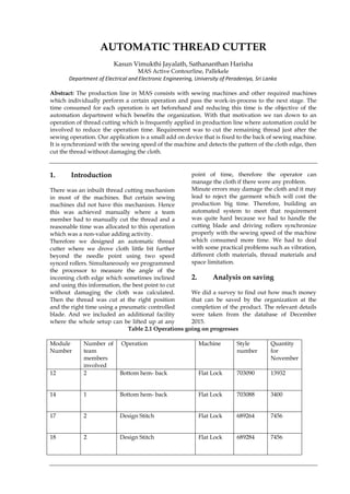
Table 2.1 Operations going on progresses
Module
Number
Number of
team
members
involved
Operation Machine Style
number
Quantity
for
November
12 2 Bottom hem- back Flat Lock 703090 13932
14 1 Bottom hem- back Flat Lock 703088 3400
17 2 Design Stitch Flat Lock 689264 7456
18 2 Design Stitch Flat Lock 689284 7456
2. Table 2.2 Operation and its TMV
Operation TMV saving
15- TCUT 50
14- TCUT 25
31- TCUT 50
32- TCUT 25
Total 150
Table 2.3 Calculation of the saving
Style No QTY TMV Saving Total
703090 13932 300 4179600
703088 3400 150 510000
689284 7456 300 2236800
689284 7456 300 2236800
Total TMV saving 958160
/ TMV per min /16.67
Total minute saving per
month
5496.82 mins
Total hour saving per
month
91.8 hr
Value per hour *$ 5.4 per hr
Total money saving per
month
$495.7
Eliminated TMV
Sample 703088
Assume: Each operation has 2 cutting operations
3. Mechanical design
3. Figure 3.1 Mechanical design
Figure 3.2 Placement of the Thread Cutter
3.1 Pneumatic cylinders and pneumatic
cutters
The mechanical parts of the innovation was
designed to fix it at the back of the sewing
machine. L shaped iron bracket (Thickness –
0.5mm) hold the Iron frame carrying rollers,
stepper motor and cutter. 2 pneumatic
cylinders (Single Rod, Double acting, 10mm
bore, and 60mm stroke) fixed to the bracket.
Those cylinders were activated and the whole
iron frame was lifted when the sewing operator
wants to remove the cloth from the machine. At
normal operation the cylinders were released
and laid down on the cloth to push the cloth
towards the cutter. The cylinders were capable
of holding a heavy weight and there was a
spring mechanisms at both rod edge to
maintain the pressure of the rollers on the cloth
and to compensate the vibration while sewing.
The cutter was placed in between two rollers
which had a single acting pneumatic cylinder
and a sharp angular blade fixed firmly at the
end of the flat rod.
3.2 Infrered sensor panel
Sensor panel consists with 7 industrially used
infrared sensors which were very reliable. The
angle of the edge of incoming cloth was
calculated using some logical combinations.
On the bed there was a reflective sticker which
reflects the infrared beam back to the sensor.
When it was covered by some non-reflective
material the sensor detects it. When cloth was
detected by one of the sensor the timer was
started to count till it reached the other end.
The time difference was calculated. This time
difference fed in to the microcontroller and the
time of cut was calculated. This decision was
made using a logarithmic scheme.
When the edge angle of the cloth was larger
(e.g.: 1st cloth piece of figure 2.1), there was a
need to pay extra care not to damage the cloth.
So a large clearance was set. When the angle
was small, the clearance was smaller.
4. Figure 3.3 logical combinations for different cloth
3.3 Rollers
Two rollers were driven by the stepper motor
placed on the top. Power was transmitted
through a belt drive to two rollers. Stepper
motor (rated current at 1.2A and 1.8 degree per
full step) had driven by the microcontroller
synchronized with sewing speed. Sewing speed
was captured using encoders fixed to the main
wheel. Bearings was penetrated to the iron
frame to ease the rotation of the rollers by
reducing the friction.
The basic requirement of the machine was to
synchronize the roller speed with the machine
sewing speed. Unless otherwise the cloth may
twists and stuck in the machine. To accomplish
this task we tapped the encoder built in the
machine which gave a pulse on each stitch
cycle. We observed that a certain distance of
cloth went inside for a single stitch cycle at a
certain sewing speed. With the knowledge of
that, we found out that distance travelled
during a cycle. That distance should be pulled
by the rollers. Then we calculated the number
of steps needed to be rotate in a stitch cycle to
match with the sewing speed assuming no slip
between rollers and cloth. The number of steps
was always changing with the change in
sewing speed.
Speed of the machine in terms of steps needed
to be found out. Hence we multiply the speed
of the machine with the ratio,
.
4. Results
We conducted few experiments to clarify the
reliability of our method. But still more number
of experiments should be conducted to bring
this innovation to the production floor. Initially
we tested couple of experiments to see whether
the rollers were synced enough to run in high
speed swing scenarios at continuouss
operation. So we inserted a piece of cloth
(length 10cm) in to the machine and to rollers.
Time taken by those two instances were
recorded for different speeds.
We tested 5 different types of cloths and
measured the mean cutting distance from the
edge of the cloth achieved in each trail.
5. Table 4.1 synchronizing the rollers
Table 4.2 Results of the cutting distances
Type Cutting distance from
edge (mm)
Desired distance
from the edge (mm)
Error(mm)
Type 1 (45 even slope) 15 10 5
Type 2(-45 even slope) 16 10 6
Type 3 (45 convex
type)
9 5 4
Type 4 (0 flat) 6 1 5
Type 5 (45 concave
type)
12 5 7
5. Conclusions
We completed designing and implementing
two rollers which rotate at the same sewing
speed which varies time to time by tapping
encoders come with the machine. The similar
thing has achieved using a mechanical method
before. We replaced that mechanical method in
to an electronic feedback loop system.
Applying this method, any number of rollers
attached to a stepper motor can be driven by
the operator sitting at any place around. We
had to compromise with time to complete some
important part of the project. 10 weeks of
training period was not enough to complete
final part of the project. We built the
mechanical parts and coding completely, but
could not perform enough test runs to ensure
the efficiency of the system.
Future work
We are currently extending the coding to build
up a closed loop system to the entire system
which has not yet been completed. Mechanical
faults were affecting to the end results badly.
To get rid of those practical issues, we are
trying to machine those mechanical parts using
CNC.
Acknowledgement
We would like to express our deepest
appreciation to all those who provided us the
possibility to complete this project to this
extent. A special gratitude to the former
General Manager Mr Venura Aththanayake
and Mr. Viraj Wijesinghe, Mr Chathushka
Hendalage whose contribution in stimulating
suggestions and encouragement helped us to
coordinate our project in a successive manner.
Furthermore we would also like to
acknowledge with much appreciation the
crucial role of the staff of MAS-Contourline,
pallekele specially Mr Lasantha De Silva and
Mr. Prasanna who gave the permission to use
all required equipment and the necessary
materials to complete our product.
We would also like to appreciate the guidance
given by other supervisor as well as the panels
especially in our presentations by providing
their comment and advices to improve our
presentation skills.
Through sewing machine
(sec)
Through rollers(sec) Difference (sec)
20 22 2
25 28 3
30 34 4
40 45 5
50 55 5
60 67 7
80 88 8